EP0073723B1 - Vorrichtung zur Lokalisierung von Bruchstellen in Hüllen von Brennelementen eines schnellen Brüters - Google Patents
Vorrichtung zur Lokalisierung von Bruchstellen in Hüllen von Brennelementen eines schnellen Brüters Download PDFInfo
- Publication number
- EP0073723B1 EP0073723B1 EP82401596A EP82401596A EP0073723B1 EP 0073723 B1 EP0073723 B1 EP 0073723B1 EP 82401596 A EP82401596 A EP 82401596A EP 82401596 A EP82401596 A EP 82401596A EP 0073723 B1 EP0073723 B1 EP 0073723B1
- Authority
- EP
- European Patent Office
- Prior art keywords
- sampling
- selector
- axis
- conduit
- enclosure
- Prior art date
- Legal status (The legal status is an assumption and is not a legal conclusion. Google has not performed a legal analysis and makes no representation as to the accuracy of the status listed.)
- Expired
Links
Images

Classifications
-
- G—PHYSICS
- G21—NUCLEAR PHYSICS; NUCLEAR ENGINEERING
- G21C—NUCLEAR REACTORS
- G21C17/00—Monitoring; Testing ; Maintaining
- G21C17/02—Devices or arrangements for monitoring coolant or moderator
- G21C17/04—Detecting burst slugs
- G21C17/042—Devices for selective sampling, e.g. valves, shutters, rotatable selector valves
-
- Y—GENERAL TAGGING OF NEW TECHNOLOGICAL DEVELOPMENTS; GENERAL TAGGING OF CROSS-SECTIONAL TECHNOLOGIES SPANNING OVER SEVERAL SECTIONS OF THE IPC; TECHNICAL SUBJECTS COVERED BY FORMER USPC CROSS-REFERENCE ART COLLECTIONS [XRACs] AND DIGESTS
- Y02—TECHNOLOGIES OR APPLICATIONS FOR MITIGATION OR ADAPTATION AGAINST CLIMATE CHANGE
- Y02E—REDUCTION OF GREENHOUSE GAS [GHG] EMISSIONS, RELATED TO ENERGY GENERATION, TRANSMISSION OR DISTRIBUTION
- Y02E30/00—Energy generation of nuclear origin
- Y02E30/30—Nuclear fission reactors
Definitions
- the invention relates to a device for locating a ruptured cladding of combustible needles in a fast neutron nuclear reactor.
- This coolant circulating in the reactor generally consisting of liquid sodium, passes through the fuel assemblies from bottom to top, over their entire height, so that in the event of a leak in a fuel assembly, the sodium leaving this assembly at its upper part is charged with fission products emitting neutrons.
- the device for detecting and locating sheath ruptures in the fast neutron reactor assemblies takes liquid sodium above each of the core assemblies.
- a sheath rupture localization module brings together a large number of sampling conduits each corresponding to an assembly of the core.
- Such a sheath rupture localization module comprises a sampling selector capable of carrying out successive samples of sodium from each of the conduits associated with each of the assemblies.
- a pump sucks the liquid sodium from the various liquid samples corresponding to each of the assemblies.
- the selector generally comprises an arm or sampling conduit driven in rotation the end of which is placed in communication successively with the ends of the conduits associated with the assemblies which terminate in the lower part of the selector constituted by a flat plate having the dimension of the cross section of the module.
- the modules generally fixed on a rotating plug called a cover-core plug formed in the horizontal slab covering the reactor vessel, penetrate this vessel and immerse in the liquid sodium vertical to the core, their lower parts receiving the sampling conduits arranged a little above the reactor core.
- the core In large-power fast neutron nuclear reactors currently being built, the core consists of a very large number of assemblies, of the order of 500. Under these conditions, it is necessary to have a fairly large number of modules sheath location localization since the number of conduits connected to each of the modules is limited if we want to use modules with a cross section which is not too large.
- Six modules are generally used which exercise surveillance on a number of assemblies less than 100. This relatively high number of modules increases the construction and maintenance costs of the nuclear reactor and complicates the detection and localization operations of cladding failures.
- the number of conduits connected to the selector can be easily increased, by increasing the height of the cylindrical casing of the selector and the length of the stroke of the mobile sampling device.
- the central part of the module is occupied by the drive shaft of the selector, so that the sodium taken from the selector must be evacuated by a tube disposed laterally inside the module.
- an electric conduction pump arranged centrally in the module but comprising a lateral pumping conduit interposed on the path of the sodium withdrawn.
- Such an electric conduction pump has very poor efficiency and poor reliability.
- the device for measuring the neutron activity of sodium must be placed above the cap of the reactor core cover, so that it is necessary to take measurements. concerning the containment and protection against radiation of radioactive sodium brought into this area.
- the object of the invention is therefore to propose a device for locating a sheath rupture in the fuel assemblies of a fast neutron nuclear reactor, by taking coolant from the reactor at the top of the fuel assemblies immersed in this liquid. and measurement of the neutron activity of the sampled liquid comprising at least one sheath rupture localization module comprising a sampling selector constituted by a cylindrical envelope with a vertical axis the lateral surface of which is pierced with orifices arranged in a helical path to which lead to the outside of the envelope of the sampling tubes each associated with an assembly and by a sampling conduit the lower part of which is bent and ends with a sampling head moving in rubbing contact with the internal surface of the cylindrical envelope following a helical path passing through each of the orifices for the successive removal a u level of each of the tubes by means of a tubular drive member carrying the sampling conduit disposed with its vertical axis and coinciding with the axis of the cylindrical casing of the selector displaceable with the sampling conduit in a
- the sampling duct is constituted by a tube mounted inside and along the axis of the drive member, pivotally about a horizontal axis located at its upper part, this tube carrying the sampling head at its lower part, a counterweight pivotally mounted on the drive member about a horizontal axis resting on the sampling head to hold it against the internal surface of the envelope and the drive being engaged by its external threaded surface with a nut carried by a support fixed inside the envelope and integral in rotation with a gear with respect to which the drive member is free in translation in the vertical direction , this gear being associated with a rotational drive means disposed laterally offset with respect to the axis of the selector.
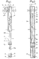
- Figure 1 shows in an elevational view with partial section, a module of a sheath rupture location device according to the prior art.
- FIG. 2 shows in a view identical to the view of Figure 1, a module of a sheath rupture location device according to the invention.
- Figure 3 shows in a sectional view through a vertical plane, the lower part of the module shown in Figure 2 including in particular the selector.
- the localization module consists of a vertical structure of great length, the lower part of which is arranged vertically from the reactor core.
- the lower part of this module consists of the selector 3, the lower plate 4 of which is pierced with orifices each receiving a sampling tube 4, the end of which is not connected to the selector and is disposed above a particular assembly of the core.
- the movable sampling duct 6 is rotated by a shaft 7 passing axially through the module along its entire height to the drive motor 8 disposed above the cap of the core cover.
- the holes in the selector plate 4 are arranged in at least one circular ring, the rotation of the sampling conduit 6 allowing scanning of all of these holes and a sampling in all of the conduits 5, during a full arm 6.
- the liquid sodium taken off by the arm 6 is discharged through a tube 10a, 10b, 10c, the course of which is offset laterally relative to the axis of the module.
- An electromagnetic conduction pump 12 allows pumping in the branch 10a of the tube, despite the lateral arrangement of the tube relative to the pump. Thanks to the pump 12, the samples taken from the upper part of the assemblies arrive successively at the upper part of the module constituted by a neutron activity measurement device 14 inside which the part 10b of the tube allows circulation of the active sodium. in the vicinity of a neutron detector.
- the measuring device 14 includes thick lead isolation walls 15 and a neutron detector 16 disposed outside these walls. The entire device 14 rests on the upper surface of the cap of the core cover 1.
- the sodium descends via the branch 10c of the tube into the reactor vessel, where it mixes with the cooling sodium filling the vessel, below level 2.
- a flow meter 17 On the branch 10a of the tube corresponding to the upward path of sodium is placed a flow meter 17 making it possible to measure the flow of sodium at all times.
- the movable sampling conduit 23 of the selector comes into contact at its lower end, successively with each of the conduits 21 each connected to an assembly of the heart.
- the selector drive shaft 24 is arranged offset from the axis of the module and connected at its upper part to a motor 25.
- the device 30 consists of a sodium reservoir fed at its lower part by the pipe 26 and inside which a detector plunges of neutrons 31.
- Three tubes 32 arranged laterally serve as an overflow for the tank 30 and pour the sodium into the reactor vessel where it mixes with the cooling sodium filling the latter.
- the entire module is contained in a cylindrical envelope 33 of great height.
- a closure device 34 of absorbent material, of great thickness, makes it possible to completely isolate the area where active sodium is found from the area outside the tank disposed above the cap of the core cover.
- the lower part of the module is seen comprising the selector, the non-removable cylindrical envelope 35 of which constitutes an extension of a sleeve 37 surrounding the cylindrical envelope 33 of the module.
- the lateral surface of the cylindrical envelope 35 is pierced with holes 36 arranged in a helical path on this envelope.
- each of the holes 36 is housed the end of a tube 21 associated with an assembly of the heart.
- the movable sampling duct of the selector consists of a tube 40 bent at its lower end and secured, at this end, to a sampling head 41 made of a wear-resistant metallic material.
- a fixed support 42 connected to the casing 33 by means of tie rods 43 and placed in a fixed angular position relative to the cylindrical casing 35 by means of a keying 44.
- the support 42 rests by its lower part on the cylindrical casing 35.
- This support 42 carries at its lower part in the vicinity of the axis ZZ 'of the module and of the cylindrical casing 35 a nut 45 rigidly secured to the support.
- a gear 47 is rotatably mounted on the support 42 at its upper part.
- the axis of rotation of the gear 47 and the axis of symmetry of the nut 45 coincide with the axis ZZ 'of the module and the selector.
- the sampling duct 40 of the selector is mounted in the axial direction ZZ ′ inside a tubular drive member 48 having a thread 49 over part of its length.
- the nut 45 and the threaded part of the drive member 48 constitute a screw-nut system allowing a helical movement of the sampling conduit by rotation of the drive member 48 about the axis ZZ '.
- the sampling conduit 40 is in fact connected at its upper part to the drive member 48 so as to be integral with this member 48 in rotation about the axis ZZ 'and in translation along this axis.
- the tubular drive member 48 is rotated about the axis ZZ ′ by means of the gear 47 engaged on an upper non-threaded part of the drive member 48.
- This upper part of the member 40 has grooves 50 which engage in corresponding grooves machined in the internal bore of the gear 47.
- tubular drive member 48 is integral in rotation about the axis ZZ 'but free in translation in the direction ZZ' relative to the gear 47 rotatably mounted on the fixed support 42.
- the gear 47 is itself driven in rotation by means of a gear 52 mounted on the control shaft 24 of the selector itself driven in rotation by means of gears 53 and 54 by the motor 25.
- the sampling duct 40 is made integral in rotation and in vertical translation with the drive member 48 by means of ends of axes 63 which are horizontal and integral with the member 48 on which the sampling duct 40 is rotatably mounted. In this way, the sampling conduit 40 and the sampling head 41 can pivot slightly inside the drive member 48, around the horizontal direction common to the two ends of axes 63.
- a counterweight 55 is mounted articulated at 56 on the end of the tubular support 48 and is supported on the sampling head 41, to hold it against the interior surface of the cylindrical casing 35 with a constant pressure.
- the counterweight 55 is produced in the form of a crown portion disposed around the tubular drive member 48 and engaging laterally with two pins such as 57 secured to the sampling head 41.
- the counterweight 55 can thus exert on the sampling head 41 a force keeping it applied against the interior surface of the cylindrical envelope 35.
- the counterweight is also secured to an actuating finger 58 which causes it to tilt slowly in the direction of arrow 59 when the end of this actuating finger comes into contact with a ramp 60 machined on the external surface of the nut 45 on the fixed support 42, at the end of movement upwards. tubular drive member 48.
- This tilting of the counterweight 55 causes movement of the sampling head 41 moving it away from the inner surface of the cylindrical envelope 35, by means of the pins 57 engaged in an opening formed in the counterweight.
- the transport of the sodium taken off via the pipe 40 to the upper part of the module is ensured by means of the axial pipe 26 on which the electromagnetic induction pump 28 is disposed axially.
- the lower part of the conduit 26 is engaged in an enlarged portion 61 of the conduit 40, the seal between the conduit 26 and the conduit 40 being ensured by virtue of the spherical end 62 of the conduit 26 coming into contact with the cylindrical surface of the portion 61 of the duct 40.
- This sphere-to-cylinder seal remains during the small amplitude pivoting of the sampling duct 40 during its movement inside the cylindrical envelope 35.
- the tubular drive member 48, the sampling conduit 40 and the head 41 move in a helical movement corresponding to a scanning of the holes 36 by the head 41.
- the latter is held against the internal surface of the casing 35 with constant pressure thanks to the counterweight 55. This thus avoids excessive friction and any loss of sealing between the sampling head and the conduits 37.
- the pump 28 exerts in the conduit 40, via the conduit 26, a suction allowing the removal of sodium from the tubes 37 then the transport of this sodium into the reservoir 30.
- the detector 31 makes it possible to detect an abnormal neutron activity in the sample. Knowledge of the position of the selector then makes it possible to determine a sheath rupture at the level of a particular assembly.
- the sample is then discharged through the overflow 32.
- the flow meter 29 is a conventional electromagnetic flow meter but it is placed inside a metal jacket which allows significant heat dissipation.
- the electromagnetic induction pump 28 placed axially on the sodium pipe 26 has an excellent efficiency and the pumping takes place under very good conditions.
- All of the sodium used for detection remains in an area located under the top plate of the core cover cap so that no precaution is to be taken to isolate the measurement area.
- the fixing by tie rods of the support 42 resting by its lower part on the casing 35 eliminates the drawbacks coming from differential expansions between the plug of the core cover and the casing of the module.
- the support 42 is indeed free to move in the axial direction relative to the casing 33 of the module.
- the finger 58 then comes into contact with the ramp 60 which clears the sampling head 41 inwardly in order to detach it from the surface of the envelope 35. We can then continue to raise the device inside the support 42.
- tie rods 43 it is then possible to reassemble the entire mobile part of the selector independently of the sleeve 37.
- the main advantages of the device according to the invention are to allow perfect contact between the sampling head and the cylindrical casing of the selector, without risk of blocking, to facilitate the suction pumping of the sodium samples by allowing an axial path of this sodium and perform the activity measurement on the sodium samples below the level of the core cover.
- the device according to the invention makes it possible to connect the selector to a large number of sampling tubes, for example 225 tubes corresponding to an equal number of assemblies. In this way it is no longer necessary to use a large number of modules but only two or three modules for the nuclear reactors currently constructed.
- the drive member 48 can carry grooves inside which comes engage one or more keys integral with the gear 47.
- connection between the sampling conduit and the tubular drive member 48 different from a connection by the ends of horizontal axes.
- the invention applies in all cases where the detection and localization of sheath rupture is carried out in a fast neutron nuclear reactor.
Landscapes
- Physics & Mathematics (AREA)
- Engineering & Computer Science (AREA)
- Plasma & Fusion (AREA)
- General Engineering & Computer Science (AREA)
- High Energy & Nuclear Physics (AREA)
- Monitoring And Testing Of Nuclear Reactors (AREA)
- Sampling And Sample Adjustment (AREA)
Claims (7)
Applications Claiming Priority (2)
| Application Number | Priority Date | Filing Date | Title |
|---|---|---|---|
| FR8116559 | 1981-08-31 | ||
| FR8116559A FR2512259B1 (fr) | 1981-08-31 | 1981-08-31 | Dispositif de localisation de rupture de gaine dans les assemblages combustibles d'un reacteur nucleaire a neutrons rapides |
Publications (2)
| Publication Number | Publication Date |
|---|---|
| EP0073723A1 EP0073723A1 (de) | 1983-03-09 |
| EP0073723B1 true EP0073723B1 (de) | 1988-11-09 |
Family
ID=9261793
Family Applications (1)
| Application Number | Title | Priority Date | Filing Date |
|---|---|---|---|
| EP82401596A Expired EP0073723B1 (de) | 1981-08-31 | 1982-08-30 | Vorrichtung zur Lokalisierung von Bruchstellen in Hüllen von Brennelementen eines schnellen Brüters |
Country Status (3)
| Country | Link |
|---|---|
| EP (1) | EP0073723B1 (de) |
| DE (1) | DE3279212D1 (de) |
| FR (1) | FR2512259B1 (de) |
Families Citing this family (4)
| Publication number | Priority date | Publication date | Assignee | Title |
|---|---|---|---|---|
| FR2650111B1 (fr) * | 1989-07-20 | 1991-09-27 | Commissariat Energie Atomique | Dispositif de transfert d'un fluide entre deux circuits pouvant subir un deplacement relatif limite, et son application a une installation de detection de rupture de gaine dans un reacteur nucleaire a neutrons rapides |
| US5066452A (en) * | 1989-07-24 | 1991-11-19 | The Babcock & Wilcox Company | Ultrasonic profilometry system for control rod wear |
| GB2277828A (en) * | 1993-05-05 | 1994-11-09 | Nnc Ltd | Nuclear reactors |
| US11267009B1 (en) * | 2021-01-25 | 2022-03-08 | The Procter & Gamble Company | Manually operated dispensing pump |
Family Cites Families (5)
| Publication number | Priority date | Publication date | Assignee | Title |
|---|---|---|---|---|
| US3005467A (en) * | 1958-01-24 | 1961-10-24 | Bernard P Suchoza | Multi-port valve |
| GB1237536A (en) * | 1967-08-14 | 1971-06-30 | Atomic Energy Authority Uk | Improvements in or relating to equipment for testing for nuclear reactor fuel element failure |
| FR2105072B1 (de) * | 1970-09-22 | 1973-11-30 | Commissariat Energie Atomique | |
| US3870078A (en) * | 1971-11-03 | 1975-03-11 | Usc Inc | Sampling slide value |
| US4332639A (en) * | 1979-02-21 | 1982-06-01 | Electric Power Research Institute, Inc. | Failed element detection and location system and method for use in a nuclear reactor |
-
1981
- 1981-08-31 FR FR8116559A patent/FR2512259B1/fr not_active Expired
-
1982
- 1982-08-30 EP EP82401596A patent/EP0073723B1/de not_active Expired
- 1982-08-30 DE DE8282401596T patent/DE3279212D1/de not_active Expired
Also Published As
| Publication number | Publication date |
|---|---|
| FR2512259A1 (fr) | 1983-03-04 |
| FR2512259B1 (fr) | 1987-09-25 |
| DE3279212D1 (en) | 1988-12-15 |
| EP0073723A1 (de) | 1983-03-09 |
Similar Documents
| Publication | Publication Date | Title |
|---|---|---|
| EP0360629B1 (de) | Instrumentierungsvorrichtung für die Spaltzone eines Druckwasserkernreaktors und Verfahren und Vorrichtung zum Aus- und Einbau dieser Instrumentierungsvorrichtung | |
| EP0073723B1 (de) | Vorrichtung zur Lokalisierung von Bruchstellen in Hüllen von Brennelementen eines schnellen Brüters | |
| EP0272944B1 (de) | Führungs- und Positionierungsrohr für Spaltzonenmessvorrichtung eines Kernreaktors | |
| EP0185561B1 (de) | Reinigungsvorrichtung der Führungsrohre von Neutronenflussmesseinrichtungen in einem Druckwasserkernreaktor | |
| EP0148802B1 (de) | Einrichtung zur Handhabung von Brennstoffelementen und Brennstoffelement für die Vorrichtung | |
| FR2820486A1 (fr) | Organe de fermeture d'une vanne comportant un logement interieur pour une sonde permettant l'extraction de celle-ci sans demontage | |
| EP0078211A1 (de) | Vorrichtung zur Entnahme von Flüssigkeitsproben und Gerät mit einer solchen Vorrichtung | |
| EP0245167B1 (de) | Spaltzonenverschlussdeckel eines schnellen Neutronenkernreaktors | |
| FR2671225A1 (fr) | Procede et dispositif de mesure de la temperature du fluide de refroidissement primaire d'un reacteur nucleaire. | |
| EP0081180B1 (de) | Maschine zum Einstechen um ein Rohr herum, insbesondere während des Anbringens dieses Rohres auf einem Kernreaktorgefäss | |
| FR2501892A1 (fr) | Reacteur nucleaire a dispositif de guidage des grappes de controle | |
| FR2702875A1 (fr) | Procédé et dispositif de remplacement d'un adaptateur de traversée du couvercle de la cuve d'un réacteur nucléaire. | |
| FR2598211A1 (fr) | Dispositif d'alimentation a distance en pieces de forme cylindrique d'une machine automatique telle qu'une machine de bouchage de tubes d'un generateur de vapeur d'un reacteur nucleaire a eau sous pression | |
| CH507570A (fr) | Bras de manutention | |
| FR2605787A1 (fr) | Installation de manutention du combustible dans un reacteur nucleaire a neutrons rapides | |
| EP0048672B1 (de) | Atomkernreaktor mit Wärmetauschern in integrierter Bauweise | |
| FR2700059A1 (fr) | Dispositif et procédé de contrôle de la surface intérieure d'une pièce tubulaire. | |
| EP0014606B1 (de) | Führungsvorrichtung für Bedienungsleitungen des kleinen Drehdeckels eines Kernreaktors | |
| EP0064462A1 (de) | Schneller Kernreaktor mit einem aus Brennstabbündeln bestehenden Kern und Einrichtung zur Lokalisierung defekter Brennstabbündel | |
| EP0265311A1 (de) | Kühlvorrichtung des Hauptgefässes eines flüssigkeitsmetallgekühlten schnellen Neutronenreaktors | |
| EP4309189B1 (de) | Vorrichtung zum heben oder senken eines kernbrennstabbündels in einem becken einer kerntechnischen anlage | |
| EP0218485B1 (de) | Handhabungseinrichtung zum Einführen und Herausziehen einer Apparatur durch eine Öffnung in einem dichten Gehäuse | |
| FR2464538A1 (fr) | Dispositif etalon pour l'emission de produits de fission pour la detection de rupture de gaine dans un reacteur nucleaire | |
| EP0011005A1 (de) | Probenahmekopf für Kühlmittel eines Kernreaktors | |
| EP0426519A1 (de) | Abdichtungsvorrichtung einer vertikalen Rohrleitung, die ein längliches Element trägt und leitet |
Legal Events
| Date | Code | Title | Description |
|---|---|---|---|
| PUAI | Public reference made under article 153(3) epc to a published international application that has entered the european phase |
Free format text: ORIGINAL CODE: 0009012 |
|
| AK | Designated contracting states |
Designated state(s): BE DE GB IT NL |
|
| 17P | Request for examination filed |
Effective date: 19830503 |
|
| GRAA | (expected) grant |
Free format text: ORIGINAL CODE: 0009210 |
|
| AK | Designated contracting states |
Kind code of ref document: B1 Designated state(s): BE DE GB IT NL |
|
| ITF | It: translation for a ep patent filed | ||
| REF | Corresponds to: |
Ref document number: 3279212 Country of ref document: DE Date of ref document: 19881215 |
|
| GBT | Gb: translation of ep patent filed (gb section 77(6)(a)/1977) | ||
| PLBE | No opposition filed within time limit |
Free format text: ORIGINAL CODE: 0009261 |
|
| STAA | Information on the status of an ep patent application or granted ep patent |
Free format text: STATUS: NO OPPOSITION FILED WITHIN TIME LIMIT |
|
| 26N | No opposition filed | ||
| PGFP | Annual fee paid to national office [announced via postgrant information from national office to epo] |
Ref country code: DE Payment date: 19900724 Year of fee payment: 9 |
|
| PGFP | Annual fee paid to national office [announced via postgrant information from national office to epo] |
Ref country code: BE Payment date: 19900803 Year of fee payment: 9 |
|
| PGFP | Annual fee paid to national office [announced via postgrant information from national office to epo] |
Ref country code: GB Payment date: 19900810 Year of fee payment: 9 |
|
| ITTA | It: last paid annual fee | ||
| PGFP | Annual fee paid to national office [announced via postgrant information from national office to epo] |
Ref country code: NL Payment date: 19900831 Year of fee payment: 9 |
|
| PG25 | Lapsed in a contracting state [announced via postgrant information from national office to epo] |
Ref country code: GB Effective date: 19910830 |
|
| PG25 | Lapsed in a contracting state [announced via postgrant information from national office to epo] |
Ref country code: BE Effective date: 19910831 |
|
| BERE | Be: lapsed |
Owner name: NOVATOME Effective date: 19910831 |
|
| PG25 | Lapsed in a contracting state [announced via postgrant information from national office to epo] |
Ref country code: NL Effective date: 19920301 |
|
| NLV4 | Nl: lapsed or anulled due to non-payment of the annual fee | ||
| GBPC | Gb: european patent ceased through non-payment of renewal fee | ||
| PG25 | Lapsed in a contracting state [announced via postgrant information from national office to epo] |
Ref country code: DE Effective date: 19920501 |