EP0074120A2 - Zylinderblock - Google Patents
Zylinderblock Download PDFInfo
- Publication number
- EP0074120A2 EP0074120A2 EP82108270A EP82108270A EP0074120A2 EP 0074120 A2 EP0074120 A2 EP 0074120A2 EP 82108270 A EP82108270 A EP 82108270A EP 82108270 A EP82108270 A EP 82108270A EP 0074120 A2 EP0074120 A2 EP 0074120A2
- Authority
- EP
- European Patent Office
- Prior art keywords
- cylinder block
- oil pan
- section
- integral
- installation rail
- Prior art date
- Legal status (The legal status is an assumption and is not a legal conclusion. Google has not performed a legal analysis and makes no representation as to the accuracy of the status listed.)
- Granted
Links
Images

Classifications
-
- F—MECHANICAL ENGINEERING; LIGHTING; HEATING; WEAPONS; BLASTING
- F02—COMBUSTION ENGINES; HOT-GAS OR COMBUSTION-PRODUCT ENGINE PLANTS
- F02F—CYLINDERS, PISTONS OR CASINGS, FOR COMBUSTION ENGINES; ARRANGEMENTS OF SEALINGS IN COMBUSTION ENGINES
- F02F7/00—Casings, e.g. crankcases
- F02F7/0065—Shape of casings for other machine parts and purposes, e.g. utilisation purposes, safety
- F02F7/0068—Adaptations for other accessories
-
- F—MECHANICAL ENGINEERING; LIGHTING; HEATING; WEAPONS; BLASTING
- F02—COMBUSTION ENGINES; HOT-GAS OR COMBUSTION-PRODUCT ENGINE PLANTS
- F02F—CYLINDERS, PISTONS OR CASINGS, FOR COMBUSTION ENGINES; ARRANGEMENTS OF SEALINGS IN COMBUSTION ENGINES
- F02F7/00—Casings, e.g. crankcases
- F02F7/0002—Cylinder arrangements
- F02F7/0007—Crankcases of engines with cylinders in line
-
- F—MECHANICAL ENGINEERING; LIGHTING; HEATING; WEAPONS; BLASTING
- F02—COMBUSTION ENGINES; HOT-GAS OR COMBUSTION-PRODUCT ENGINE PLANTS
- F02F—CYLINDERS, PISTONS OR CASINGS, FOR COMBUSTION ENGINES; ARRANGEMENTS OF SEALINGS IN COMBUSTION ENGINES
- F02F7/00—Casings, e.g. crankcases
- F02F7/0065—Shape of casings for other machine parts and purposes, e.g. utilisation purposes, safety
- F02F7/008—Sound insulation
-
- F—MECHANICAL ENGINEERING; LIGHTING; HEATING; WEAPONS; BLASTING
- F02—COMBUSTION ENGINES; HOT-GAS OR COMBUSTION-PRODUCT ENGINE PLANTS
- F02B—INTERNAL-COMBUSTION PISTON ENGINES; COMBUSTION ENGINES IN GENERAL
- F02B75/00—Other engines
- F02B75/16—Engines characterised by number of cylinders, e.g. single-cylinder engines
- F02B75/18—Multi-cylinder engines
- F02B2075/1804—Number of cylinders
- F02B2075/1816—Number of cylinders four
Definitions
- This invention relates to a cylinder block of an automotive internal combustion engine, configurated to reduce vibration noise emitted therefrom.
- cylinder blocks In connection with automotive engine cylinder blocks, they are usually formed with a so-called skirt section which is integral with the side wall sections of the cylinder block and defines thereinside the upper part of a crankcase chamber.
- the skirt section is formed at its lower part with a flange to which an oil pan is secured.
- a conventional cylinder block is usually not provided with any special measure to increase the rigidity against flexure and torsion applied to the cylinder block entire. Accordingly, the cylinder block tends to generate flexural and torsional vibrations, thereby emitting vibration noise from the cylinder block itself. Additionally, such cylinder block vibration induces the vibration of an oil pan and the like covers, thus further increasing noise emission from an engine.
- a cylinder block according to the present invention comprises an oil pan installation rail to which an oil pan is to be secured.
- the oil pan installation rail is integral with a skirt section of the cylinder block at the lower part and generally in the shape of a quadrangular pyramid whose width and height gradually increase in the direction from its front end to its rear end.
- the oil pan installation rail is hollow.
- a transmission installation section to which a transmission is secured is integral with the cylinder block.
- the transmission installation section is integral with the rear end of the oil pan installation rail.
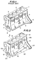
- a conventional cylinder block 1 of so-called half-skirt type of an automotive engine will be described-along with its major shortcomings.
- the cylinder block 1 is formed at its upper part with a plurality of cylinder-barrels 2.
- a water jacket (not shown) through which engine coolant flows is formed between a side wall 3 and the cylinder-barrels 2.
- a so-called skirt section 4 is integral with the lower part of the side-wall 3 and extends downwardly.
- the skirt section 4 is widened downwardly forming an inclined flat surface as shown in Fig. 1; otherwise the skirt section may be bulged outwardly.
- the skirt section 4 is formed along its bottom edge an oil pan installation flange 5 to which an oil pan (not shown) is to be secured, so that the oil pan installation flange 5 extends from the front end of the cylinder block 1 toward the rear end of the cylinder block 1 to which a transmission is to be installed.
- a transmission installation section 6 Projected laterally and outwardly from the rear end part of the cylinder block 1 is a transmission installation section 6 to which the transmission is secured.
- the transmission installation section 6 is integral with the oil pan installation flange 5.
- a plurality of main bearing support sections 7 are formed inside of the skirt section 4 and integral with the cylinder block 1.
- a plurality of main bearing caps 8 are securely attached to the main bearing support sections 7 so as to rotatably support a crankshaft through main bearing metals each being located between the each main bearing support section and each main bearing cap 8.
- any special measure is not taken in order to improve the rigidity against flexure in upward-and-downward direction and in rightward-and-leftward direction, and therefore flexural and torsional vibrations tends to be generated in the cylinder block entire by vibration input from the crankshaft which vibration input is due to impact force by combustion within the cylinder-barrels.
- the cylinder block itself emits high level noise, while vibrating the oil pan serving as a secondary noise source.
- the connection-rigidity between the transmission and the cylinder block rear end is relatively low, and accordingly the natural frequency of the combined vibration of cylinder block and transmission vibrations becomes lower, thereby increasing low-frequency noise within a passenger compartment.
- a preferred embodiment of a cylinder block of the present invention is illustrated by the reference numeral 10.
- the cylinder block 10 is formed at its upper part with a plurality of cylinder-barrels 12.
- the cylinder-barrels 12 are located to be interposed between two opposite side wall sections 14 of the cylinder block 10 in a manner to form a water jacket W, through which engine coolant flows, between the cylinder-barrels and each side wall section 14.
- a so-called skirt section 16 includes oppositely disposed side walls 16a, 16b each of which is formed integral with the lower part of each cylinder block side wall section 14 and extends from the front end section 10a of the cylinder block 10 to the rear end section 10b of the cylinder block 10 to which rear end section a transmission (not shown) is to be securely connected.
- the skirt section 16 also extends downwardly to be widened downward so as to define thereinside the upper part of a crankcase.
- a plurality of main bearing support sections 18 are disposed inside of the skirt section 16 and integral with the cylinder block 10. Additionally, a plurality of main bearing caps 20 are secured to the main bearing support sections 18, respectively.
- the journal of a crankshaft (not shown) is rotatably supported between each main bearing support section 18 and each main bearing cap 20 through a bearing metal (not shown).
- two oppositely disposed oil pan installation rails 22 are located at the lower part of the cylinder block 10 and extend parallelly along the length of the cylinder block 10, i.e., in the direction from the cylinder block front end section 10a toward the cylinder block rear end section 10b.
- Each oil pan installation rail 22 is integral with the lower part of one of skirt section walls 16a, 16b.
- the oil pan installation section 22 is generally in the shape of a quadrangular pyramid whose width and height are generally the same, in which the width and height of the oil pan installation section gradually increase in the direction from the cylinder block front end section 10a to the cylinder block rear end section 10b.
- the oil pan installation rail 22 is formed hollow as best shown in Fig.
- the oil pan installation rail 22 is integral at its rear end with one of two transmission installation sections 24 which are integral with and extend oppositely laterally from the cylinder block rear and section 10b.
- the rear end of the oil pan installation rail 22 is located in the vicinity of the cylinder block rear end section 10b and is largest in width and height.
- the oil pan installation rails 22 are formed at its bottom wall 20b with bolt holes 26 in which bolts (not shown) are disposed to secure the oil pan to the oil pan installation rails 22. It is to be noted that in case of making hollow the oil pan installation rails 22 during casing, cores (not shown) corresponding to the hollows of the rails 22 can be supported through these bolt holes 26.
- each oil pan installation rail 22 serves as reinforcement members, and therefore the cylinder block 10 is greatly improved in rigidity against flexure and torsion applied to the cylinder block entire. Furthermore, each oil pan installation rail 22 is hollow and so formed that the width and height gradually increase from the cylinder block front end section toward the cylinder block rear end section. Therefore, flexural and torsional vibrations of the cylinder block can be effectively suppressed only with the minimum weight increase, thereby reducing noise emission from the cylinder block itself and from covers such as the oil pan.
- the oil pan installation rails 22 are integral with the transmission installation sections, the connection-rigidity between the transmission and the cylinder block 10 can be improved and accordingly noise generation from a transmission case is also suppressed, thereby noticeably reducing low-frequency noise within a passenger compartment.
- the rigidity of the cylinder block itself and the connection-rigidity with the transmission can be improved without a considerable weight increase, thereby effectively reducing noise emission from the engine while preventing engine weight increase.
Landscapes
- Engineering & Computer Science (AREA)
- Chemical & Material Sciences (AREA)
- Combustion & Propulsion (AREA)
- Mechanical Engineering (AREA)
- General Engineering & Computer Science (AREA)
- Cylinder Crankcases Of Internal Combustion Engines (AREA)
Applications Claiming Priority (2)
| Application Number | Priority Date | Filing Date | Title |
|---|---|---|---|
| JP1981133788U JPS5840538U (ja) | 1981-09-09 | 1981-09-09 | シリンダブロツク |
| JP133788/81U | 1981-09-09 |
Publications (3)
| Publication Number | Publication Date |
|---|---|
| EP0074120A2 true EP0074120A2 (de) | 1983-03-16 |
| EP0074120A3 EP0074120A3 (en) | 1983-04-20 |
| EP0074120B1 EP0074120B1 (de) | 1985-12-27 |
Family
ID=15113017
Family Applications (1)
| Application Number | Title | Priority Date | Filing Date |
|---|---|---|---|
| EP82108270A Expired EP0074120B1 (de) | 1981-09-09 | 1982-09-08 | Zylinderblock |
Country Status (4)
| Country | Link |
|---|---|
| US (1) | US4473042A (de) |
| EP (1) | EP0074120B1 (de) |
| JP (1) | JPS5840538U (de) |
| DE (1) | DE3268141D1 (de) |
Cited By (1)
| Publication number | Priority date | Publication date | Assignee | Title |
|---|---|---|---|---|
| EP0152857A3 (en) * | 1980-10-07 | 1985-12-11 | Nissan Motor Co., Ltd. | Cylinder block of engine |
Families Citing this family (8)
| Publication number | Priority date | Publication date | Assignee | Title |
|---|---|---|---|---|
| DE4324609C2 (de) * | 1993-07-22 | 1997-10-16 | Avl Verbrennungskraft Messtech | Kurbelgehäuse für Brennkraftmaschinen |
| DE9319054U1 (de) * | 1993-12-11 | 1995-04-13 | FEV Motorentechnik GmbH & Co. KG, 52078 Aachen | Kolbenmaschine, insbesondere Kolbenbrennkraftmaschine mit versteiftem Motorblock |
| US5662080A (en) * | 1994-11-12 | 1997-09-02 | Yamaha Hatsudoki Kabushiki Kaisha | Engine crankcase |
| US7219642B1 (en) * | 2006-02-10 | 2007-05-22 | Gm Global Technology Operations, Inc. | Powertrain assembly and integral truss oil pan therefor |
| US9416749B2 (en) | 2013-12-09 | 2016-08-16 | Ford Global Technologies, Llc | Engine having composite cylinder block |
| US9341136B2 (en) | 2013-12-09 | 2016-05-17 | Ford Global Technologies, Llc | Engine having composite cylinder block |
| EP3214294B1 (de) * | 2014-10-27 | 2020-05-13 | Aichi Machine Industry Co., Ltd. | Motorblock und verbrennungsmotor damit |
| CN114718755B (zh) * | 2022-04-25 | 2025-05-27 | 广西玉柴机器股份有限公司 | 降高及两式固定的气缸体结构 |
Family Cites Families (5)
| Publication number | Priority date | Publication date | Assignee | Title |
|---|---|---|---|---|
| US2027940A (en) * | 1931-12-23 | 1936-01-14 | Packard Motor Car Co | Internal combustion engine |
| US2381745A (en) * | 1941-11-28 | 1945-08-07 | Chrysler Corp | Coupling |
| US2436729A (en) * | 1943-03-10 | 1948-02-24 | Paxman Edward Philip | Construction of internal-combustion engines |
| US2378045A (en) * | 1943-05-17 | 1945-06-12 | Ford Motor Co | Cylinder construction |
| BE794095A (fr) * | 1972-02-04 | 1973-05-16 | Berliet Automobiles | Perfectionnement au carter des moteurs a combustion interne de vehicules |
-
1981
- 1981-09-09 JP JP1981133788U patent/JPS5840538U/ja active Granted
-
1982
- 1982-09-07 US US06/415,729 patent/US4473042A/en not_active Expired - Fee Related
- 1982-09-08 DE DE8282108270T patent/DE3268141D1/de not_active Expired
- 1982-09-08 EP EP82108270A patent/EP0074120B1/de not_active Expired
Cited By (2)
| Publication number | Priority date | Publication date | Assignee | Title |
|---|---|---|---|---|
| EP0152857A3 (en) * | 1980-10-07 | 1985-12-11 | Nissan Motor Co., Ltd. | Cylinder block of engine |
| US4569317A (en) * | 1980-10-07 | 1986-02-11 | Nissan Motor Co., Ltd. | Cylinder block of engine |
Also Published As
| Publication number | Publication date |
|---|---|
| JPS638836Y2 (de) | 1988-03-16 |
| US4473042A (en) | 1984-09-25 |
| DE3268141D1 (en) | 1986-02-06 |
| EP0074120B1 (de) | 1985-12-27 |
| JPS5840538U (ja) | 1983-03-17 |
| EP0074120A3 (en) | 1983-04-20 |
Similar Documents
| Publication | Publication Date | Title |
|---|---|---|
| EP0054474B1 (de) | Kraftfahrzeugbrennkraftmaschine mit innerer Verbrennung | |
| EP0052818B1 (de) | Kurbelgehäuse für eine Brennkraftmaschine | |
| US4520770A (en) | Automotive internal combustion engine with bearing beam structure | |
| US4473042A (en) | Cylinder block | |
| EP0077033B1 (de) | Lagerträgerstruktur | |
| US4466401A (en) | Internal combustion engine with bearing beam structure | |
| US4520771A (en) | Internal combustion engine | |
| EP0088339B1 (de) | Lagerträgerstruktur für eine Brennkraftmaschine | |
| EP0065664B1 (de) | Motor mit innerer Verbrennung mit einer Balkenauflagerung | |
| US4453509A (en) | Internal combustion engine with bearing beam structure | |
| US4474148A (en) | Internal combustion engine with bearing beam structure | |
| US4458640A (en) | Internal combustion engine with bearing beam structure | |
| EP0056347A2 (de) | Brennkraftmaschine mit niedrigem Geräuschpegel | |
| EP0152857A2 (de) | Zylinderblock einer Brennkraftmaschine | |
| US4445472A (en) | Internal combustion engine with bearing beam structure | |
| JP2606040B2 (ja) | エンジンのシリンダボディ | |
| US4445471A (en) | Low noise level automotive internal combustion engine | |
| JPS601248Y2 (ja) | 自動車用エンジン | |
| JPH0639083Y2 (ja) | エンジンの制振構造 | |
| JPH07317600A (ja) | オイルパンの騒音低減構造 | |
| JPH075237Y2 (ja) | エンジンのシリンダブロック構造 | |
| JPH0666199A (ja) | エンジンのクランクケース |
Legal Events
| Date | Code | Title | Description |
|---|---|---|---|
| PUAI | Public reference made under article 153(3) epc to a published international application that has entered the european phase |
Free format text: ORIGINAL CODE: 0009012 |
|
| PUAL | Search report despatched |
Free format text: ORIGINAL CODE: 0009013 |
|
| 17P | Request for examination filed |
Effective date: 19820908 |
|
| AK | Designated contracting states |
Designated state(s): DE FR GB |
|
| AK | Designated contracting states |
Designated state(s): DE FR GB |
|
| RAP1 | Party data changed (applicant data changed or rights of an application transferred) |
Owner name: NISSAN MOTOR CO., LTD. |
|
| GRAA | (expected) grant |
Free format text: ORIGINAL CODE: 0009210 |
|
| AK | Designated contracting states |
Designated state(s): DE FR GB |
|
| REF | Corresponds to: |
Ref document number: 3268141 Country of ref document: DE Date of ref document: 19860206 |
|
| ET | Fr: translation filed | ||
| PLBI | Opposition filed |
Free format text: ORIGINAL CODE: 0009260 |
|
| 26 | Opposition filed |
Opponent name: KLOECKNER-HUMBOLDT-DEUTZ AG Effective date: 19860925 |
|
| PLBN | Opposition rejected |
Free format text: ORIGINAL CODE: 0009273 |
|
| STAA | Information on the status of an ep patent application or granted ep patent |
Free format text: STATUS: OPPOSITION REJECTED |
|
| 27O | Opposition rejected |
Effective date: 19881212 |
|
| PGFP | Annual fee paid to national office [announced via postgrant information from national office to epo] |
Ref country code: GB Payment date: 19910816 Year of fee payment: 10 |
|
| PGFP | Annual fee paid to national office [announced via postgrant information from national office to epo] |
Ref country code: FR Payment date: 19910906 Year of fee payment: 10 |
|
| PGFP | Annual fee paid to national office [announced via postgrant information from national office to epo] |
Ref country code: DE Payment date: 19911030 Year of fee payment: 10 |
|
| PG25 | Lapsed in a contracting state [announced via postgrant information from national office to epo] |
Ref country code: GB Effective date: 19920908 |
|
| GBPC | Gb: european patent ceased through non-payment of renewal fee |
Effective date: 19920908 |
|
| PG25 | Lapsed in a contracting state [announced via postgrant information from national office to epo] |
Ref country code: FR Effective date: 19930528 |
|
| PG25 | Lapsed in a contracting state [announced via postgrant information from national office to epo] |
Ref country code: DE Effective date: 19930602 |
|
| REG | Reference to a national code |
Ref country code: FR Ref legal event code: ST |