EP0074509A2 - Dispositif de concentration - Google Patents
Dispositif de concentration Download PDFInfo
- Publication number
- EP0074509A2 EP0074509A2 EP82107590A EP82107590A EP0074509A2 EP 0074509 A2 EP0074509 A2 EP 0074509A2 EP 82107590 A EP82107590 A EP 82107590A EP 82107590 A EP82107590 A EP 82107590A EP 0074509 A2 EP0074509 A2 EP 0074509A2
- Authority
- EP
- European Patent Office
- Prior art keywords
- stage
- evaporation
- plant according
- condensation
- separation
- Prior art date
- Legal status (The legal status is an assumption and is not a legal conclusion. Google has not performed a legal analysis and makes no representation as to the accuracy of the status listed.)
- Withdrawn
Links
Images

Classifications
-
- B—PERFORMING OPERATIONS; TRANSPORTING
- B01—PHYSICAL OR CHEMICAL PROCESSES OR APPARATUS IN GENERAL
- B01D—SEPARATION
- B01D1/00—Evaporating
- B01D1/26—Multiple-effect evaporating
-
- B—PERFORMING OPERATIONS; TRANSPORTING
- B01—PHYSICAL OR CHEMICAL PROCESSES OR APPARATUS IN GENERAL
- B01D—SEPARATION
- B01D1/00—Evaporating
- B01D1/06—Evaporators with vertical tubes
- B01D1/10—Evaporators with vertical tubes with long tubes, e.g. Kestner evaporators
Definitions
- the invention relates to an evaporation plant according to the preamble of claim 1.
- the object of the invention is to integrate the separation stage or the separation stages in the system.
- the separation stage is structurally combined with the evaporation stage or the condensation stage, the construction effort and the assembly effort become less.
- a multi-stage system that is an evaporation Separation stage assigned to the stage is preferably accommodated in the subsequent evaporation stage or the subsequent condensation stage, which reduces the number of connecting lines between the stages.
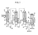
- the first evaporation stage 10 is heated by heating steam, which is fed through a nozzle 18 and discharged in a known manner.
- the product to be evaporated becomes the head 20 added to the first evaporation stage 10 and flows down through a tube bundle 22 into a space 24 from which the liquid phase is drawn off through a line 26 and fed to the next evaporation stage 12 via a pump 28.
- the evaporation stages 12 and 14 basically work like the evaporation stage 10, so that a detailed description is unnecessary. Vapors from the room 24 are fed to the second evaporation stage 12 for heating them via a line 30.
- annular wall 34 is arranged within the jacket 32 of the second evaporation stage 12 and delimits an annular space 36 between it and the jacket 32.
- This annular space 36 is open at the top and closed at the bottom. It serves to record the separation stage.
- the resulting liquid phase in this separation stage is discharged through line 38 (for details see FIG. 2) into space 40.
- the third evaporation stage 14 is constructed like the second evaporation stage, only the evaporated product is discharged from the space 42 there via a line 44 and a pump 46.
- the vapor passes through a line 48 into the condenser 16, which is to be evacuated through a connection 55 and is penetrated by cooling water pipes 50.
- this condenser 16 also contains an annular wall 52 which, together with the jacket 54 of the condensation stage 16, delimits a separation space 56.
- the condensate from the vapor is removed from the condensation stage 16 via a nozzle 58.
- the concentrate separated in this condensation stage 16 is returned to the space 42 through a line 59.
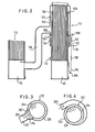
- FIG. 2 shows the lower end of a first evaporation stage 110 which is connected to a subsequent second evaporation stage 112.
- the space 124 of the first evaporation stage 110 is connected via a line 130 to a separation space 136 in the second evaporation stage 112.
- This separation space 136 is through the jacket 132 the second evaporation stage and an annular wall 134 arranged inside the jacket 132.
- the separating space is closed at the bottom by an annular base 160.
- the liquid phase collecting in the separation space 136 is discharged into the space 140 through a line 138.
- a valve 162 and a knee 164 with a draw-off valve 166 are located in the line 138.
- the level of the liquid phase in the separation space 136 can be determined through a sight glass 168.
- the upper end of the ring wall 134 is supported by webs 170 with the jacket 132.
- a preheating chamber 172 for the product to be evaporated is arranged below the separating space 136.
- the preheating chamber is heated by the vapor which is fed through line 130.
- a pipe coil 174 Inside the preheating chamber is a pipe coil 174, to which the product to be evaporated is fed through a nozzle 176 and from which the product is discharged through a nozzle 178.
- the vapors coming from line 13o condense on the heating pipes of the evaporation stage 112 and are discharged from the evaporation stage 112 through a nozzle 173. Otherwise, the interaction of the evaporation stages 110 and 112 and their structure corresponds to that of the evaporation stages 10 and 12 according to FIG. 1.
- FIG 3 shows in cross section an evaporation stage 212 which corresponds to the evaporation stage 112, but in which the annular space 236 is designed as a combined centrifugal and impact force separator.
- the vapor fed through the line 230 hits the annular wall 234 in the direction of the arrow 280 and is directed into the annular space 236 in the direction of the arrows 282, 284.
- the impact in the direction of arrow 280 results in a Stoßkraftabscheidun g, the deflection in the direction of arrows 282 and 284 to a centrifugal separation.
- vapors are fed to the evaporation stage 312 through a spiral line 330.
- This line 330 narrows and opens tangentially in the annular space 336 between the jacket 332 and the annular wall 334, so that a true centrifugal separation is obtained.
- FIG. 5 like the evaporation plant according to FIG. 1, has three evaporation stages 410, 412 and 414 and a condensation stage 416.
- the product to be evaporated is passed through preheat chambers 490, 492, 494 and 496 of condensation stage 416 and of evaporation stages 410, 412 and 414 before being fed to head 420 of the first evaporation stage.
- the coolant is supplied to the condensation stage 416 to be evacuated through a nozzle 415 and discharged from above. Otherwise, the construction corresponds to that of Figure 1., Except for the special design of the second evaporation stage 412. g In the separating chamber 436 of the second Verdampfun Slevel trays 500 (shown left) and Sports Sciences effet 502 (shown on the right) are provided.
- nozzles 504, 506 are provided, which are fed via a line 508, 510 via a pump 512 with the liquid phase that collects in the bottom region of the preheating chamber 494.
- discharge lines 509 are provided which penetrate the jacket 432 of the evaporation stage 412.
- the replacement trays 500 and the packing arrangements 502 are particularly expedient if the evaporation system is used to evaporate fruit or fruit juices. Such juices are often deprived of volatile flavoring when evaporated. Flavor concentrates are to be withdrawn from the discharge lines 509. The lower-boiling aroma concentrates become from the upper area of the evaporation stage sucked off, from the lower part of the heavier boiling flavor concentrates. The remaining liquid (called mother water) is drained off.
- the integrated deposition spaces are, therefore, together form beneficial in an evaporation plant, heating the product in succession from the 'flow-through Verdampfmaschine and are connected in parallel brüden developed an evaporation stage.
Landscapes
- Chemical & Material Sciences (AREA)
- Chemical Kinetics & Catalysis (AREA)
- Vaporization, Distillation, Condensation, Sublimation, And Cold Traps (AREA)
Applications Claiming Priority (2)
| Application Number | Priority Date | Filing Date | Title |
|---|---|---|---|
| DE19813136476 DE3136476A1 (de) | 1981-09-15 | 1981-09-15 | Eindampfanlage |
| DE3136476 | 1981-09-15 |
Publications (2)
| Publication Number | Publication Date |
|---|---|
| EP0074509A2 true EP0074509A2 (fr) | 1983-03-23 |
| EP0074509A3 EP0074509A3 (fr) | 1983-04-20 |
Family
ID=6141651
Family Applications (1)
| Application Number | Title | Priority Date | Filing Date |
|---|---|---|---|
| EP82107590A Withdrawn EP0074509A3 (fr) | 1981-09-15 | 1982-08-19 | Dispositif de concentration |
Country Status (5)
| Country | Link |
|---|---|
| EP (1) | EP0074509A3 (fr) |
| JP (1) | JPS5861801A (fr) |
| DE (1) | DE3136476A1 (fr) |
| ES (1) | ES512460A0 (fr) |
| ZA (1) | ZA826717B (fr) |
Cited By (2)
| Publication number | Priority date | Publication date | Assignee | Title |
|---|---|---|---|---|
| EP0224215A3 (fr) * | 1985-11-21 | 1988-08-03 | GEA Wiegand GmbH | Procédé de production d'un concentré d'arôme à partir d'un jus aromatique |
| WO2011135589A3 (fr) * | 2010-04-29 | 2011-12-22 | Shree Renuka Sugars Limited | Système d'évaporation |
Family Cites Families (8)
| Publication number | Priority date | Publication date | Assignee | Title |
|---|---|---|---|---|
| BE451992A (fr) * | 1941-05-19 | |||
| US2544885A (en) * | 1946-02-27 | 1951-03-13 | Gen Am Transport | Vertical tube evaporator |
| US2651356A (en) * | 1948-08-25 | 1953-09-08 | Henry M Hunter | Apparatus for evaporation |
| DE964141C (de) * | 1953-01-14 | 1957-05-16 | Rosenblads Patenter Ab | Roehreneindampfer mit Kanalwechselbetrieb |
| US2741303A (en) * | 1954-01-04 | 1956-04-10 | Whiting Corp | Long tube vertical evaporator |
| US3354932A (en) * | 1965-05-28 | 1967-11-28 | Blaw Knox Co | Multiple-effect evaporator structure |
| SE320047B (fr) * | 1967-11-22 | 1970-02-02 | Rosenlew W & Co Ab Bjoerneborg | |
| NL7513772A (nl) * | 1975-11-25 | 1977-05-27 | Stork Amsterdam | Werkwijze voor het regelen van het droge stof ge- halte bij een verdamper, alsmede verdampingsin- stallatie voor het toepassen van deze werkwijze. |
-
1981
- 1981-09-15 DE DE19813136476 patent/DE3136476A1/de not_active Withdrawn
-
1982
- 1982-05-21 ES ES512460A patent/ES512460A0/es active Granted
- 1982-08-19 EP EP82107590A patent/EP0074509A3/fr not_active Withdrawn
- 1982-09-14 JP JP57158997A patent/JPS5861801A/ja active Pending
- 1982-09-14 ZA ZA826717A patent/ZA826717B/xx unknown
Cited By (2)
| Publication number | Priority date | Publication date | Assignee | Title |
|---|---|---|---|---|
| EP0224215A3 (fr) * | 1985-11-21 | 1988-08-03 | GEA Wiegand GmbH | Procédé de production d'un concentré d'arôme à partir d'un jus aromatique |
| WO2011135589A3 (fr) * | 2010-04-29 | 2011-12-22 | Shree Renuka Sugars Limited | Système d'évaporation |
Also Published As
| Publication number | Publication date |
|---|---|
| JPS5861801A (ja) | 1983-04-13 |
| ES8304438A1 (es) | 1983-03-01 |
| ES512460A0 (es) | 1983-03-01 |
| DE3136476A1 (de) | 1983-03-31 |
| ZA826717B (en) | 1983-08-31 |
| EP0074509A3 (fr) | 1983-04-20 |
Similar Documents
| Publication | Publication Date | Title |
|---|---|---|
| DE2538472C2 (de) | Verfahren zur Durchführung einer Mehrfachverdampfung | |
| DE2333703A1 (de) | Mehrstufiger verdampfer | |
| DE10147674A1 (de) | Einrichtung zur Fallstromverdampfung einer flüssigen Substanz und anschließenden Kondensation des entstandenen Brüdens | |
| CH668162A5 (de) | Verfahren zur sterilisierung von fluessigkeiten und anlage zur durchfuehrung des verfahrens. | |
| DE2717543A1 (de) | Verfahren und verdampfer zum verdampfen einer fluessigkeit | |
| DE10207460C1 (de) | Kolonne zur Aufkonzentration von Phthalsäureanhydrid | |
| DE871295C (de) | Verfahren und Vorrichtung zur hindernisfreien Hochvakuumdestillation | |
| DE2334481B2 (de) | Vorrichtung zur Gewinnung von Reinwasser aus Seewasser | |
| EP0066790A1 (fr) | Procédé et dispositif pour la distillation à trajet court | |
| DE3854054T2 (de) | Verfahren zur Erzeugung von hoch reinem Wasser durch Destillation. | |
| EP0074509A2 (fr) | Dispositif de concentration | |
| DE3884616T2 (de) | Vorrichtung zur verdampfung von flüssigkeiten. | |
| DE2223081B2 (de) | Mehrstufenverdampfer zur gewinnung von suesswasser aus salzwasser | |
| EP0729772B1 (fr) | Evaporateur | |
| WO2000009236A1 (fr) | Installation permettant de separer un melange vapeur-liquide en ecoulement | |
| DE4223392C2 (de) | Vorrichtung zur Kondensation von Wasserdampfanteilen in einem Brüden-Luft-Gemisch, insb. bei der Zuckerfabrikation | |
| DE1030373B (de) | Verfahren und Vorrichtung zur Zerlegung von Gasgemischen bei niedriger Temperatur | |
| EP0188019A1 (fr) | Procédé de nettoyage du condensat de vapeur | |
| EP0848634B1 (fr) | Procede permettant de faire fonctionner une installation d'evaporation, et installation d'evaporation pour la mise en oeuvre de ce procede | |
| DE2837892C2 (de) | Vorrichtung zum Kondensieren von Dampf | |
| DE19521622A1 (de) | Verfahren zum Kondensieren von Dämpfen, insbesondere Brüden, und Vorrichtung zur Durchführung des Verfahrens | |
| EP1412042A2 (fr) | Ameliorations apportees a un evaporateur a film tombant pour separer des melanges de substances | |
| AT122005B (de) | Verfahren und Einrichtung zum Eindicken von Aromastoffe enthaltenden Flüssigkeiten, insbesondere von Fruchtsäften. | |
| DE2841437B2 (de) | Verfahren und Vorrichtung zum Kondensieren von Öldampf aus einem dldampfhaltigen Luftstrom | |
| DE479331C (de) | Durchleiten der Gase durch die Verdampfer der Vorrichtungen zum Verfluessigen zusammengesetzter Gasgemische |
Legal Events
| Date | Code | Title | Description |
|---|---|---|---|
| PUAI | Public reference made under article 153(3) epc to a published international application that has entered the european phase |
Free format text: ORIGINAL CODE: 0009012 |
|
| PUAL | Search report despatched |
Free format text: ORIGINAL CODE: 0009013 |
|
| AK | Designated contracting states |
Designated state(s): CH FR GB IT LI NL |
|
| AK | Designated contracting states |
Designated state(s): CH FR GB IT LI NL |
|
| 17P | Request for examination filed |
Effective date: 19830511 |
|
| STAA | Information on the status of an ep patent application or granted ep patent |
Free format text: STATUS: THE APPLICATION IS DEEMED TO BE WITHDRAWN |
|
| 18D | Application deemed to be withdrawn |
Effective date: 19840920 |
|
| RIN1 | Information on inventor provided before grant (corrected) |
Inventor name: FRANK, ERICH Inventor name: TORAN, JOSEF |