EP0074617B1 - Vorrichtung zum Sperren wenigstens einer Wähltaste bei Tastentelefonen - Google Patents
Vorrichtung zum Sperren wenigstens einer Wähltaste bei Tastentelefonen Download PDFInfo
- Publication number
- EP0074617B1 EP0074617B1 EP82108298A EP82108298A EP0074617B1 EP 0074617 B1 EP0074617 B1 EP 0074617B1 EP 82108298 A EP82108298 A EP 82108298A EP 82108298 A EP82108298 A EP 82108298A EP 0074617 B1 EP0074617 B1 EP 0074617B1
- Authority
- EP
- European Patent Office
- Prior art keywords
- bolt
- sense
- dial key
- lock
- key
- Prior art date
- Legal status (The legal status is an assumption and is not a legal conclusion. Google has not performed a legal analysis and makes no representation as to the accuracy of the status listed.)
- Expired
Links
Images
Classifications
-
- H—ELECTRICITY
- H04—ELECTRIC COMMUNICATION TECHNIQUE
- H04M—TELEPHONIC COMMUNICATION
- H04M1/00—Substation equipment, e.g. for use by subscribers
- H04M1/66—Substation equipment, e.g. for use by subscribers with means for preventing unauthorised or fraudulent calling
- H04M1/667—Preventing unauthorised calls from a telephone set
-
- H—ELECTRICITY
- H01—ELECTRIC ELEMENTS
- H01H—ELECTRIC SWITCHES; RELAYS; SELECTORS; EMERGENCY PROTECTIVE DEVICES
- H01H9/00—Details of switching devices, not covered by groups H01H1/00 - H01H7/00
- H01H9/20—Interlocking, locking, or latching mechanisms
- H01H9/28—Interlocking, locking, or latching mechanisms for locking switch parts by a key or equivalent removable member
Definitions
- the invention relates to a device for locking at least one dial key in key telephones, consisting of a hood covering the key, at least one bolt connected to it, engaging the telephone, and a lock securing this lock.
- the invention has for its object to provide a locking device of the type mentioned, which is not only small and simple, but also permanently reliable, and this object is achieved in that the latch to fit into a recess in the side surface of a Dial button is formed and arranged.
- the recesses can of course be cut into the plastic of the selector keys using a suitable cutting tool.
- a suitable cutting tool there is also the possibility, in a preferred embodiment of the invention, of designing the bolt of the locking device with a cutting edge which is arranged in such a way that a recess can be cut therein with a first rotary movement of the bolt relative to a selection key.
- the rotary movement takes place coaxially to the central longitudinal axis of a dial key or parallel to it.
- the bolt can expediently consist of one or more ring segments which are attached to the inner circumference of a rotatable hollow cylindrical support part or eccentric arm on such a radius that when the support part is rotated about the central longitudinal axis of the selector key, only in the area of the corners in its cross-sectional profile penetration.
- the bolt can have the shape of a non-circular or eccentrically mounted disc which, when the hood is in place, engages in its cross-sectional profile from the edge of the keypad only at a certain angle of rotation position at a corner or a straight side surface of a dial key.
- the invention allows different variations, which differ in the number of covered and thereby blocked dial keys and in the arrangement and design of the latch. It is often sufficient to use just a single dial key, e.g. B. to block long-distance calls. Then you get by with a very small hood, which only needs to cover this one button. Since a lock has two relatively rotatable parts, a preferably used cylinder lock z. B. the cylinder and the housing surrounding it, one of these two relatively rotatable parts of the lock can carry the latch engaging in the recess of the dial key, while the other part of the lock comes to rest on the same dial key or elsewhere on the keypad Stop is connected.
- the lock is to be set so that in its open position the hood of the locking device can be placed over the dial keys to be locked and the stop connected to the lock part comes to rest on one or more keys, whereby the rotation of this lock part relative to the keys is prevented.
- the bolt engages in the recess of at least one selection button. If the key of the lock is removed in this locked position, the two lock parts are locked against rotation, i. that is, the bolt remains in engagement with the recess in the selector key and the hood covering one or more selector keys and thereby blocking cannot be removed.
- a ring-segment-shaped bolt is attached to a hood which is fixedly connected to the housing of the lock and covers only the single key.
- the bolt can be integrally formed with the hood, but also z. B. consist of metal segments that are firmly embedded in a substantially cylindrical plastic hood.
- the hood integrated with the housing of the lock also surrounds the cylinder and the associated stop.
- the latter can e.g. B. consist of two parallel jaws, which come to rest above the recesses in the dial key on two opposite side surfaces thereof and thereby prevent rotation of the cylinder relative to the dial key.
- a second pair of stop jaws can also be present, which comes to rest on the two other side surfaces of the selector key.
- the hood which is firmly connected to the lock housing, is turned by hand by approximately 45 °.
- one or more ring segment-shaped latches which were initially located next to the side faces when the hood was loosely placed on the dial key, can enter recesses at the corners of the dial key. If the bar or bars with cutting edges to create the Ausneh In addition, if there are openings on the corners of the selector button, it is advisable to attach opposite, parallel contact surfaces to the hood to attach a tool in the manner of a wrench.
- the lock could also be connected to the cylinder and the stop attached to the hood in the locking device for locking a single selection key.
- This arrangement is also preferred if several or all keys of a keypad are to be covered and thereby blocked.
- the hood can e.g. B. in adaptation to the rectangular shape of the keypad can also be made rectangular, so that it and the housing of the lock connected to it can not rotate relative to the keypad.
- the locking device shown in FIG. 1 is used to lock a single key 10 of an indicated key telephone 12.
- the locking device designated overall by 14, consists of a cylinder lock, the housing of which is indicated by 16 and the cylinder indicated by dashed lines by means of a key 18 relative to the housing 16 20 are designated.
- a substantially hollow cylindrical hood 22 is firmly connected to the housing 16 and, as shown in FIG. 1, can be placed over the key 10 to be locked and can thereby be inserted between the adjacent keys.
- four ring segment-shaped bolts 24 are formed or attached near the lower edge of the hood 22, which are intended to engage in recesses 26 in the corners of the button 10.
- the bolts 24 lie with respect to the central longitudinal axis of the hood 22, whose inner diameter is just slightly larger than the diagonal of the button 10, on such a radius that they are in the neutral position shown in Fig. 2 next to the side surfaces of the Key 10 are outside of their profile cross-section, but penetrate into the recesses 26 when the hood 22 rotates. In this locked position of the lock 16, 20 reached after a rotation of approximately 45 °, the key 18 is removed.
- At least one side edge of the bar 24 in the form of a segment of a ring can in each case be designed as a straight or stepped cutting edge 30 which automatically cuts the recesses 26 when it is first placed on a button and the hood 22 is turned.
- the housing 16 connected to the hood 22 has parallel engagement surfaces 32 on opposite sides for a tool in the manner of a wrench.
- FIG. 3 differs from that of FIGS. 1 and 2 essentially only in that a large rectangular hood 34 is firmly connected to the housing 16 of the castle, which covers several or all keys of a key telephone. Due to its rectangular shape, the hood 34 in the attached position according to FIG. 3 also forms a stop which prevents the housing 16 from rotating relative to the keys.
- the embodiment according to FIG. 3 differs from that according to FIGS. 1 and 2 by the attachment of the bolt 24 to a bush 36 connected in a rotationally fixed manner to the cylinder 20 of the lock.
- the hood 34 and the bush 36 can e.g. B. consist of plastic, while the bolt 24 is advantageously made of metal. It can also have the shape shown in FIG. 2 in the embodiment according to FIG. 3, while the diameter of the sleeve 36 corresponds approximately to the hood 22 of the embodiment according to FIGS. 1 and 2.
- the locking device can have a lower overall height than in the embodiment of FIG. 3rd
- special cutting tools are used to produce the recesses in the selector keys instead of the self-tapping bolts, these can also have the shape of ring segments or out-of-round or eccentrically mounted disks described above. Other straight-line cutting tools can also be used. In order to facilitate the cutting process, there is the option of successively reducing the cutting edge of the bar or the special cutting tool in order to remove several chips to train. The removal of several small chips in succession can be carried out with less force than the production of a recess in a selection key in a single cut.
Landscapes
- Engineering & Computer Science (AREA)
- Computer Security & Cryptography (AREA)
- Signal Processing (AREA)
- Telephone Set Structure (AREA)
- Push-Button Switches (AREA)
- Telephone Function (AREA)
Description
- Die Erfindung betrifft eine Vorrichtung zum Sperren wenigstens einer Wähltaste bei Tastentelefonen, bestehend aus einer die Taste überdeckenden Haube, wenigstens einem mit dieser verbundenen, am Telefon angreifenden Riegel und einem diese Verriegelung sichernden Schloß.
- Während sich ein Telefon mit Wählscheibe verhältnismäßig einfach gegen unbefugten Gebrauch sperren läßt, bereitet es größere Schwierigkeiten, ein Tastentelefon zu sperren, weil die Sperrvorrichtung schlecht Halt am Telefon findet. Vorrichtungen, die den Telefonapparat teilweise umgreifen, sind sehr groß und entsprechend teuer, außerdem unhandlich und schlecht zu verstauen (z. B. DE-A-2 919 599). Sperrvorrichtungen, die an den Tasten selbst angeklemmt werden könnten, bräuchten einen aufwendigen Klemmechanismus und sind nicht wirklich zuverlässig, insbesondere, wenn nach einigem Gebrauch die Klemmkraft nachläßt.
- Der Erfindung liegt die Aufgabe zugrunde, eine Sperrvorrichtung der eingangs genannten Art zu schaffen, welche nicht nur klein und einfach, sondern auch dauerhaft zuverlässig ist, und diese Aufgabe wird erfindungsgemäß dadurch gelöst, daß der Riegel passend zum Eingriff in eine Ausnehmung in der Seitenfläche einer Wähltaste ausgebildet und angeordnet ist.
- Das Einschneiden der Ausnehmungen in den Kunststoff der Wähltasten kann selbstverständlich mit einem geeigneten Schneidwerkzeug geschehen. Daneben besteht aber auch die Möglichkeit, in einer bevorzugten Ausführungsform der Erfindung den Riegel der Sperrvorrichtung mit einer Schneidkante auszubilden, welche derart angeordnet ist, daß bei einer ersten Drehbewegung des Riegels relativ zu einer Wähltaste darin eine Ausnehmung einschneidbar ist. Je nach der Form des Riegels findet dabei die Drehbewegung koaxial zur Mittellängsachse einer Wähltaste statt oder parallel zu dieser. Im erstgenannten Fall kann der Riegel zweckmäßigerweise aus einem oder mehreren Ringsegmenten bestehen, die am inneren Umfang eines drehbaren hohlzylindrischen Tragteils oder Exzenterarms auf einem solchen Radius angebracht sind, daß sie bei Drehung des Tragteils um die Mittellängsachse der Wähltaste nur im Bereich der Ekken in deren Querschnittsprofil eindringen. Im anderen Fall kann der Riegel die Form einer unrunden oder exzentrisch gelagerten Scheibe haben, welche bei aufgesetzter Haube vom Rand des Tastenfeldes aus nur bei bestimmter Drehwinkelstellung an einer Ecke oder einer geraden Seitenfläche einer Wähltaste in deren Querschnittsprofil eingreift.
- Die Erfindung gestattet verschiedene Variationen, die sich durch die Zahl der überdeckten und dadurch gesperrten Wähltasten sowie durch die Anordnung und Ausführung der Riegel unterscheiden. Oft genügt es, nur eine einzige Wähltaste, z. B. die für Ferngespräche, zu sperren. Dann kommt man mit einer sehr kleinen Haube aus, welche nur diese eine Taste zu überdecken braucht. Da ein Schloß zwei relativ zueinander drehbare Teile hat, ein vorzugsweise benutztes Zylinderschloß z. B. den Zylinder und das diesen umgebende Gehäuse, kann eines dieser beiden relativ zueinander drehbaren Teile des Schlosses den in die Ausnehmung der Wähltaste eingreifenden Riegel tragen, während das andere Teil des Schlosses mit einem an derselben Wähltaste oder an anderer Stelle des Tastenfelds zur Anlage kommenden Anschlag verbunden ist. Das Schloß ist so einzustellen, daß sich in seiner geöffneten Stellung die Haube der Sperrvorrichtung über die zu sperrenden Wähltasten setzen läßt und dabei der mit dem einen Schloßteil verbundene Anschlag zur Anlage an einer oder mehreren Tasten kommt, wodurch die Drehung dieses Schloßteils relativ zu den Tasten verhindert wird. Bei der anschließenden Relativdrehung des mit dem Riegel verbundenen Schloßteils aus der Öffnungs- in die Schließstellung kommt der Riegel zum Eingriff in die Ausnehmung wenigstens einer Wähltaste. Wird in dieser Sperrstellung der Schlüssel des Schlosses abgezogen, so sind die beiden Schloßteile gegen Drehung gesperrt, d. h., der Riegel bleibt in Eingriff mit der Ausnehmung in der Wähltaste und die eine oder mehrere Wähltasten überdekkende und dadurch sperrende Haube läßt sich nicht entfernen.
- In einer bevorzugten Ausführungsform der Erfindung, die zum Sperren einer einzelnen Wähltaste bestimmt ist, ist ein ringsegmentförmiger Riegel an einer mit dem Gehäuse des Schlosses fest verbundenen, nur die einzelne Taste überdeckenden Haube angebracht. Der Riegel kann einstückig mit der Haube ausgebildet sein, aber auch z. B. aus Metallsegmenten bestehen, die in eine im wesentlichen zylindrische Haube aus Kunststoff fest eingebettet sind. Die mit dem Gehäuse des Schlosses vereinigte Haube umgibt auch den Zylinder und den damit verbundenen Anschlag. Letzterer kann z. B. aus zwei parallelen Backen bestehen, die oberhalb der Ausnehmungen in der Wähltaste an zwei gegenüberliegenden Seitenflächen derselben zur Anlage kommen und dadurch eine Drehung des Zylinders relativ zur Wähltaste verhindern. Es versteht sich, daß auch noch ein zweites Paar Anschlagbacken vorhanden sein kann, welches an den beiden anderen Seitenflächen der Wähltaste zur Anlage kommt. Um die Sperrvorrichtung nach dem losen Aufsetzen auf die Wähltaste in Sperrstellung zu bringen, wird in diesem Fall die mit dem Schloßgehäuse fest verbundene Haube von Hand um etwa 45° gedreht. Dadurch können ein oder mehrere ringsegmentförmige Riegel, die sich beim losen Aufsetzen der Haube auf die Wähltaste zunächst neben deren Seitenflächen befanden, in Ausnehmungen an den Ecken der Wähltaste eintreten. Wenn der oder die Riegel mit Schneidkanten zur Erzeugung der Ausnehmungen an den Ecken der Wähltaste versehen sind, empfiehlt es sich, an der Haube gegenüberliegende parallele Angriffsflächen zum Ansetzen eines Werkzeugs nach Art eines Schraubenschlüssels anzubringen.
- In alternativer Ausführung könnte bei der Sperrvorrichtung zum Sperren einer einzelnen Wähltaste der Riegel auch mit dem Zylinder verbunden und der Anschlag an der Haube angebracht sein. Diese Anordnung wird auch dann bevorzugt, wenn mehrere oder alle Tasten eines Tastenfelds überdeckt und dadurch gesperrt werden sollen. In diesem Fall kann die Haube z. B. in Anpassung an die rechteckige Form des Tastenfelds ebenfalls rechteckig gestaltet werden, so daß sie sich und auch das mit ihr verbundene Gehäuse des Schlosses relativ zum Tastenfeld nicht drehen kann. Beim Drehen des Zylinders mit Hilfe des Schlüssels aus der geöffneten in die Sperrstellung des Schlosses wird ein, z. B. wiederum kreissegmentförmiger, Riegel aus einer neutralen Stellung neben der Seitenfläche einer Wähltaste in eine Ausnehmung in der Ecke einer Wähltaste gebracht. Diese Verriegelung an einer einzigen mit Ausnehmungen versehenen Wähltaste genügt, um die Abdeckhaube auf dem gesamten Tastenfeld zu halten.
- Die Erfindung wird nachstehend anhand von in der Zeichnung dargestellten Ausführungsbeispielen näher erläutert. Es zeigt
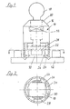
- Fig. 1 eine Sperrvorrichtung gemäß der Erfindung für eine einzelne Wähltaste;
- Fig. 2 einen Querschnitt durch die Sperrvorrichtung nach Fig. 1;
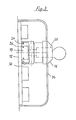
- Fig. 3 eine Sperrvorrichtung gemäß der Erfindung für ein Tastenfeld.
- Die in Fig. 1 dargestellte Sperrvorrichtung dient zum Sperren einer einzelnen Taste 10 eines angedeuteten Tastentelefons 12. Die insgesamt mit 14 bezeichnete Sperrvorrichtung besteht aus einem Zylinderschloß, dessen Gehäuse mit 16 und dessen durch einen Schlüssel 18 relativ zum Gehäuse 16 drehbarer, gestrichelt angedeuteter Zylinder mit 20 bezeichnet sind. Mit dem Gehäuse 16 ist eine im wesentlichen hohlzylindrische Haube 22 fest verbunden, die, wie in Fig. 1 gezeigt, über die zu sperrende Taste 10 gestülpt und dabei zwischen die benachbarten Tasten eingeführt werden kann. Nahe der Unterkante der Haube 22 sind gemäß Fig. 2 vier ringsegmentförmige Riegel 24 ausgebildet oder angebracht, die dazu bestimmt sind, in Ausnehmungen 26 in den Ecken der Taste 10 einzugreifen. Zu diesem Zweck liegen die Riegel 24 mit Bezug auf die Mittellängsachse der Haube 22, deren Innendurchmesser gerade etwas größer ist als die Diagonale der Taste 10, auf einem solchen Radius, das sie sich in der in Fig. 2 dargestellten neutralen Lage neben den Seitenflächen der Taste 10 außerhalb von deren Profilquerschnitt befinden, aber bei Drehung der Haube 22 in die Ausnehmungen 26 eindringen. In dieser, nach einer Drehung von etwa 45° erreichten Sperrstellung des Schlosses 16, 20 wird der Schlüssel 18 abgezogen.
- Das Herausdrehen der Riegel 24 aus den Ausnehmungen 26 wird dadurch verhindert, daß am Zylinder 20 zwei gegenüberliegende parallele Anschlagbacken 28 angebracht sind, welche an gegenüberliegenden Seitenflächen der Taste 10 anliegen.
- Wenigstens eine Seitenkante der ringsegmentförmigen Riegel 24 kann jeweils als gerade oder stufenförmig abgesetzte Schneidkante 30 ausgebildet sein, welche beim erstmaligen Aufsetzen auf eine Taste und Drehen der Haube 22 selbsttätig die Ausnehmungen 26 schneidet. Um hierbei ein größeres Drehmoment aufbringen zu können, hat das mit der Haube 22 verbundene Gehäuse 16 auf gegenüberliegenden Seiten parallele Angriffsflächen 32 für ein Werkzeug nach Art eines Schraubenschlüssels.
- Die Ausführung nach Fig. 3 unterscheidet sich von der nach Fig. 1 und 2 im wesentlichen nur dadurch, daß mit dem Gehäuse 16 des Schlosses eine große rechteckige Haube 34 fest verbunden ist, welche mehrere oder alle Tasten eines Tastentelefons überdeckt. Infolge ihrer rechteckigen Form bildet die Haube 34 in der aufgesetzten Stellung nach Fig. 3 gleichzeitig einen Anschlag, der eine Drehung des Gehäuses 16 relativ zu den Tasten verhindert.
- Weiterhin unterscheidet sich das Ausführungsbeispiel nach Fig. 3 von dem nach Fig. 1 und 2 durch die Anbringung des Riegels 24 an einer mit dem Zylinder 20 des Schlosses drehfest verbundenen Büchse 36. Die Haube 34 und die Büchse 36 können z. B. aus Kunststoff bestehen, während man den Riegel 24 zweckmäßigerweise aus Metall fertigt. Er kann auch bei der Ausführung nach Fig. 3 die in Fig. 2 gezeigte Form haben, während die Büchse 36 im Durchmesser etwa der Haube 22 der Ausführung nach Fig. 1 und 2 entspricht.
- Durch einzelne Aussparungen in der Haube 34 über bestimmten Wähltasten kann erreicht werden, daß auch bei gesperrtem Telefon ein Notruf möglich ist.
- Wenn das Schloß 16, 20 nicht, wie gemäß Fig. 3, über einer Wähltaste, sondern seitlich neben dem Tastenfeld an einer über dieses hinausreichenden Haube angebracht wird und mit dem Zylinder 20 eine unrunde oder exzentrisch gelagerte Scheibe fest verbunden ist, die in Sperrstellung in eine Ausnehmung einer Wähltaste am Rand des Tastenfelds eingreift, kann die Sperrvorrichtung eine niedrigere Bauhöhe haben als bei dem Ausführungsbeispiel nach Fig. 3.
- Werden zum Herstellen der Ausnehmungen in den Wähltasten statt der selbstschneidenden Riegel besondere Schneidwerkzeuge benutzt, so können auch diese die vorstehend beschriebene Form von Ringsegmenten bzw. unrunder oder exzentrisch gelagerter Scheiben haben. Daneben kommen auch andere, geradlinig schneidende Werkzeuge in Frage. Um den Schneidvorgang zu erleichtern, besteht die Möglichkeit, die Schneidkante des Riegels bzw. des besonderen Schneidwerkzeugs zum Abheben mehrerer Späne nacheinander stufenförmig auszubilden. Das Abtragen mehrerer kleiner Späne nacheinander läßt sich mit geringerer Kraft ausführen als die Herstellung einer Ausnehmung in einer Wähltaste in einem einzigen Schnitt.
Claims (10)
Priority Applications (1)
| Application Number | Priority Date | Filing Date | Title |
|---|---|---|---|
| AT82108298T ATE11474T1 (de) | 1981-09-12 | 1982-09-09 | Vorrichtung zum sperren wenigstens einer waehltaste bei tastentelefonen. |
Applications Claiming Priority (2)
| Application Number | Priority Date | Filing Date | Title |
|---|---|---|---|
| DE19813136274 DE3136274A1 (de) | 1981-09-12 | 1981-09-12 | "vorrichtung zum sperren wenigstens einer waehltaste bei tastentelefonen" |
| DE3136274 | 1981-09-12 |
Publications (2)
| Publication Number | Publication Date |
|---|---|
| EP0074617A1 EP0074617A1 (de) | 1983-03-23 |
| EP0074617B1 true EP0074617B1 (de) | 1985-01-23 |
Family
ID=6141524
Family Applications (1)
| Application Number | Title | Priority Date | Filing Date |
|---|---|---|---|
| EP82108298A Expired EP0074617B1 (de) | 1981-09-12 | 1982-09-09 | Vorrichtung zum Sperren wenigstens einer Wähltaste bei Tastentelefonen |
Country Status (3)
| Country | Link |
|---|---|
| EP (1) | EP0074617B1 (de) |
| AT (1) | ATE11474T1 (de) |
| DE (2) | DE3136274A1 (de) |
Families Citing this family (2)
| Publication number | Priority date | Publication date | Assignee | Title |
|---|---|---|---|---|
| IE58852B1 (en) * | 1985-12-04 | 1993-11-17 | Smith Philip | A security device for a telephone instrument |
| CN108320945B (zh) * | 2018-04-09 | 2025-04-25 | 广东电网有限责任公司 | 一种零线相防误操作的低压隔离开关装置 |
Family Cites Families (4)
| Publication number | Priority date | Publication date | Assignee | Title |
|---|---|---|---|---|
| NL7117128A (de) * | 1971-12-14 | 1973-06-18 | ||
| US4236395A (en) * | 1979-03-05 | 1980-12-02 | Avaiusini Mauricio V | Bolt type lock |
| DE2919599A1 (de) * | 1979-05-16 | 1980-11-27 | Franz Halouska | Sperrvorrichtung fuer fernsprechgeraete |
| DE3043583A1 (de) * | 1980-11-19 | 1982-06-24 | Jürgen 7500 Karlsruhe Bayer | Vorrichtung zur verhinderung des unbefugten betaetigens eines tastentelefonapparates |
-
1981
- 1981-09-12 DE DE19813136274 patent/DE3136274A1/de not_active Withdrawn
-
1982
- 1982-09-09 AT AT82108298T patent/ATE11474T1/de active
- 1982-09-09 DE DE8282108298T patent/DE3262057D1/de not_active Expired
- 1982-09-09 EP EP82108298A patent/EP0074617B1/de not_active Expired
Also Published As
| Publication number | Publication date |
|---|---|
| DE3262057D1 (en) | 1985-03-07 |
| DE3136274A1 (de) | 1983-03-24 |
| EP0074617A1 (de) | 1983-03-23 |
| ATE11474T1 (de) | 1985-02-15 |
Similar Documents
| Publication | Publication Date | Title |
|---|---|---|
| DE4322672B4 (de) | Motorisch angetriebene Feinsäge | |
| DE69902797T2 (de) | Sicherheitsvorrichtung die das funktionieren eines misch- oder küchengeräts verhindert wenn den deckel des arbeitsbehälters nicht korrekt positioniert ist | |
| EP0152564A2 (de) | Werkzeugbefestigung | |
| DE3211511A1 (de) | Zugentlastung bewirkende kabeldurchfuehrung | |
| DE3405885C1 (de) | Einrichtung zum Befestigen einer Schleifscheibe an der Schleifspindel einer tragbaren Winkelschleifmaschine | |
| DE4409312A1 (de) | Wellenarretiervorrichtung für ein motorisch antreibbares Werkzeug | |
| DE102015107720B3 (de) | Schienengeführtes Schneidwerkzeug | |
| DE2601319A1 (de) | An einem pfosten, insbesondere dem haltestellenpfosten einer autobus- oder einer strassenbahnlinie, anbringbarer informationskasten | |
| DE8327663U1 (de) | Kappsaege | |
| DE3835822C2 (de) | ||
| EP0074617B1 (de) | Vorrichtung zum Sperren wenigstens einer Wähltaste bei Tastentelefonen | |
| EP0775548B1 (de) | Kreissäge | |
| DE3838198A1 (de) | Werkzeugmaschine | |
| EP2260974A1 (de) | Werkstückhalter für eine Planschleifmaschine | |
| DE2305001A1 (de) | Absenkbare verriegelung fuer container und wechselaufbauten | |
| DE69319694T2 (de) | Ein Instrument mit einem entfernbaren Deckel | |
| EP0715564B1 (de) | Kapp-, gehrungs- und tischsäge | |
| DE3527611C2 (de) | ||
| DE4237055C1 (de) | Labormühle mit feststellbarem Mahlbecher | |
| DE8632048U1 (de) | Werkstücktisch zum Anbau von Handkreissägen | |
| DE520683C (de) | Sicherheitsschloss mit einer in der Ebene des Riegelschaftes liegenden Drehscheibe | |
| DE2745191C2 (de) | Steckschlüsselschloß | |
| EP0339177A2 (de) | Vorrichtung zum Sägen | |
| DE505406C (de) | Zeilenschaltvorrichtung fuer Schreibmaschinen | |
| DE3644999C2 (de) |
Legal Events
| Date | Code | Title | Description |
|---|---|---|---|
| PUAI | Public reference made under article 153(3) epc to a published international application that has entered the european phase |
Free format text: ORIGINAL CODE: 0009012 |
|
| AK | Designated contracting states |
Designated state(s): AT CH DE FR GB IT LI |
|
| 17P | Request for examination filed |
Effective date: 19830910 |
|
| GRAA | (expected) grant |
Free format text: ORIGINAL CODE: 0009210 |
|
| AK | Designated contracting states |
Designated state(s): AT CH DE FR GB IT LI |
|
| PG25 | Lapsed in a contracting state [announced via postgrant information from national office to epo] |
Ref country code: IT Free format text: LAPSE BECAUSE OF FAILURE TO SUBMIT A TRANSLATION OF THE DESCRIPTION OR TO PAY THE FEE WITHIN THE PRESCRIBED TIME-LIMIT;WARNING: LAPSES OF ITALIAN PATENTS WITH EFFECTIVE DATE BEFORE 2007 MAY HAVE OCCURRED AT ANY TIME BEFORE 2007. THE CORRECT EFFECTIVE DATE MAY BE DIFFERENT FROM THE ONE RECORDED. Effective date: 19850123 |
|
| REF | Corresponds to: |
Ref document number: 11474 Country of ref document: AT Date of ref document: 19850215 Kind code of ref document: T |
|
| REF | Corresponds to: |
Ref document number: 3262057 Country of ref document: DE Date of ref document: 19850307 |
|
| ET | Fr: translation filed | ||
| PLBE | No opposition filed within time limit |
Free format text: ORIGINAL CODE: 0009261 |
|
| STAA | Information on the status of an ep patent application or granted ep patent |
Free format text: STATUS: NO OPPOSITION FILED WITHIN TIME LIMIT |
|
| 26N | No opposition filed | ||
| PGFP | Annual fee paid to national office [announced via postgrant information from national office to epo] |
Ref country code: AT Payment date: 19860915 Year of fee payment: 5 |
|
| PG25 | Lapsed in a contracting state [announced via postgrant information from national office to epo] |
Ref country code: AT Effective date: 19870909 |
|
| PG25 | Lapsed in a contracting state [announced via postgrant information from national office to epo] |
Ref country code: LI Effective date: 19870930 Ref country code: CH Effective date: 19870930 |
|
| REG | Reference to a national code |
Ref country code: CH Ref legal event code: PL |
|
| PGFP | Annual fee paid to national office [announced via postgrant information from national office to epo] |
Ref country code: FR Payment date: 19890928 Year of fee payment: 8 |
|
| PGFP | Annual fee paid to national office [announced via postgrant information from national office to epo] |
Ref country code: GB Payment date: 19890930 Year of fee payment: 8 |
|
| PG25 | Lapsed in a contracting state [announced via postgrant information from national office to epo] |
Ref country code: GB Effective date: 19900909 |
|
| GBPC | Gb: european patent ceased through non-payment of renewal fee | ||
| PG25 | Lapsed in a contracting state [announced via postgrant information from national office to epo] |
Ref country code: FR Effective date: 19910530 |
|
| REG | Reference to a national code |
Ref country code: FR Ref legal event code: ST |
|
| PGFP | Annual fee paid to national office [announced via postgrant information from national office to epo] |
Ref country code: DE Payment date: 19931125 Year of fee payment: 12 |
|
| PG25 | Lapsed in a contracting state [announced via postgrant information from national office to epo] |
Ref country code: DE Effective date: 19950601 |