EP0074702A2 - Dispositif pour le dégouttement d'un gaz inerte liquéfié dans une boîte - Google Patents
Dispositif pour le dégouttement d'un gaz inerte liquéfié dans une boîte Download PDFInfo
- Publication number
- EP0074702A2 EP0074702A2 EP82302931A EP82302931A EP0074702A2 EP 0074702 A2 EP0074702 A2 EP 0074702A2 EP 82302931 A EP82302931 A EP 82302931A EP 82302931 A EP82302931 A EP 82302931A EP 0074702 A2 EP0074702 A2 EP 0074702A2
- Authority
- EP
- European Patent Office
- Prior art keywords
- gas
- nozzle
- dropping
- liquified
- valve
- Prior art date
- Legal status (The legal status is an assumption and is not a legal conclusion. Google has not performed a legal analysis and makes no representation as to the accuracy of the status listed.)
- Withdrawn
Links
Images


Classifications
-
- F—MECHANICAL ENGINEERING; LIGHTING; HEATING; WEAPONS; BLASTING
- F17—STORING OR DISTRIBUTING GASES OR LIQUIDS
- F17C—VESSELS FOR CONTAINING OR STORING COMPRESSED, LIQUEFIED OR SOLIDIFIED GASES; FIXED-CAPACITY GAS-HOLDERS; FILLING VESSELS WITH, OR DISCHARGING FROM VESSELS, COMPRESSED, LIQUEFIED, OR SOLIDIFIED GASES
- F17C9/00—Methods or apparatus for discharging liquefied or solidified gases from vessels not under pressure
-
- F—MECHANICAL ENGINEERING; LIGHTING; HEATING; WEAPONS; BLASTING
- F17—STORING OR DISTRIBUTING GASES OR LIQUIDS
- F17C—VESSELS FOR CONTAINING OR STORING COMPRESSED, LIQUEFIED OR SOLIDIFIED GASES; FIXED-CAPACITY GAS-HOLDERS; FILLING VESSELS WITH, OR DISCHARGING FROM VESSELS, COMPRESSED, LIQUEFIED, OR SOLIDIFIED GASES
- F17C6/00—Methods and apparatus for filling vessels not under pressure with liquefied or solidified gases
-
- F—MECHANICAL ENGINEERING; LIGHTING; HEATING; WEAPONS; BLASTING
- F17—STORING OR DISTRIBUTING GASES OR LIQUIDS
- F17C—VESSELS FOR CONTAINING OR STORING COMPRESSED, LIQUEFIED OR SOLIDIFIED GASES; FIXED-CAPACITY GAS-HOLDERS; FILLING VESSELS WITH, OR DISCHARGING FROM VESSELS, COMPRESSED, LIQUEFIED, OR SOLIDIFIED GASES
- F17C2203/00—Vessel construction, in particular walls or details thereof
- F17C2203/03—Thermal insulations
- F17C2203/0304—Thermal insulations by solid means
- F17C2203/0329—Foam
-
- F—MECHANICAL ENGINEERING; LIGHTING; HEATING; WEAPONS; BLASTING
- F17—STORING OR DISTRIBUTING GASES OR LIQUIDS
- F17C—VESSELS FOR CONTAINING OR STORING COMPRESSED, LIQUEFIED OR SOLIDIFIED GASES; FIXED-CAPACITY GAS-HOLDERS; FILLING VESSELS WITH, OR DISCHARGING FROM VESSELS, COMPRESSED, LIQUEFIED, OR SOLIDIFIED GASES
- F17C2203/00—Vessel construction, in particular walls or details thereof
- F17C2203/06—Materials for walls or layers thereof; Properties or structures of walls or their materials
- F17C2203/0602—Wall structures; Special features thereof
- F17C2203/0607—Coatings
-
- F—MECHANICAL ENGINEERING; LIGHTING; HEATING; WEAPONS; BLASTING
- F17—STORING OR DISTRIBUTING GASES OR LIQUIDS
- F17C—VESSELS FOR CONTAINING OR STORING COMPRESSED, LIQUEFIED OR SOLIDIFIED GASES; FIXED-CAPACITY GAS-HOLDERS; FILLING VESSELS WITH, OR DISCHARGING FROM VESSELS, COMPRESSED, LIQUEFIED, OR SOLIDIFIED GASES
- F17C2205/00—Vessel construction, in particular mounting arrangements, attachments or identifications means
- F17C2205/03—Fluid connections, filters, valves, closure means or other attachments
- F17C2205/0302—Fittings, valves, filters, or components in connection with the gas storage device
- F17C2205/0323—Valves
- F17C2205/0326—Valves electrically actuated
-
- F—MECHANICAL ENGINEERING; LIGHTING; HEATING; WEAPONS; BLASTING
- F17—STORING OR DISTRIBUTING GASES OR LIQUIDS
- F17C—VESSELS FOR CONTAINING OR STORING COMPRESSED, LIQUEFIED OR SOLIDIFIED GASES; FIXED-CAPACITY GAS-HOLDERS; FILLING VESSELS WITH, OR DISCHARGING FROM VESSELS, COMPRESSED, LIQUEFIED, OR SOLIDIFIED GASES
- F17C2205/00—Vessel construction, in particular mounting arrangements, attachments or identifications means
- F17C2205/03—Fluid connections, filters, valves, closure means or other attachments
- F17C2205/0302—Fittings, valves, filters, or components in connection with the gas storage device
- F17C2205/0323—Valves
- F17C2205/0332—Safety valves or pressure relief valves
-
- F—MECHANICAL ENGINEERING; LIGHTING; HEATING; WEAPONS; BLASTING
- F17—STORING OR DISTRIBUTING GASES OR LIQUIDS
- F17C—VESSELS FOR CONTAINING OR STORING COMPRESSED, LIQUEFIED OR SOLIDIFIED GASES; FIXED-CAPACITY GAS-HOLDERS; FILLING VESSELS WITH, OR DISCHARGING FROM VESSELS, COMPRESSED, LIQUEFIED, OR SOLIDIFIED GASES
- F17C2205/00—Vessel construction, in particular mounting arrangements, attachments or identifications means
- F17C2205/03—Fluid connections, filters, valves, closure means or other attachments
- F17C2205/0302—Fittings, valves, filters, or components in connection with the gas storage device
- F17C2205/0338—Pressure regulators
-
- F—MECHANICAL ENGINEERING; LIGHTING; HEATING; WEAPONS; BLASTING
- F17—STORING OR DISTRIBUTING GASES OR LIQUIDS
- F17C—VESSELS FOR CONTAINING OR STORING COMPRESSED, LIQUEFIED OR SOLIDIFIED GASES; FIXED-CAPACITY GAS-HOLDERS; FILLING VESSELS WITH, OR DISCHARGING FROM VESSELS, COMPRESSED, LIQUEFIED, OR SOLIDIFIED GASES
- F17C2221/00—Handled fluid, in particular type of fluid
- F17C2221/01—Pure fluids
- F17C2221/016—Noble gases (Ar, Kr, Xe)
-
- F—MECHANICAL ENGINEERING; LIGHTING; HEATING; WEAPONS; BLASTING
- F17—STORING OR DISTRIBUTING GASES OR LIQUIDS
- F17C—VESSELS FOR CONTAINING OR STORING COMPRESSED, LIQUEFIED OR SOLIDIFIED GASES; FIXED-CAPACITY GAS-HOLDERS; FILLING VESSELS WITH, OR DISCHARGING FROM VESSELS, COMPRESSED, LIQUEFIED, OR SOLIDIFIED GASES
- F17C2223/00—Handled fluid before transfer, i.e. state of fluid when stored in the vessel or before transfer from the vessel
- F17C2223/01—Handled fluid before transfer, i.e. state of fluid when stored in the vessel or before transfer from the vessel characterised by the phase
- F17C2223/0146—Two-phase
- F17C2223/0153—Liquefied gas, e.g. LPG, GPL
-
- F—MECHANICAL ENGINEERING; LIGHTING; HEATING; WEAPONS; BLASTING
- F17—STORING OR DISTRIBUTING GASES OR LIQUIDS
- F17C—VESSELS FOR CONTAINING OR STORING COMPRESSED, LIQUEFIED OR SOLIDIFIED GASES; FIXED-CAPACITY GAS-HOLDERS; FILLING VESSELS WITH, OR DISCHARGING FROM VESSELS, COMPRESSED, LIQUEFIED, OR SOLIDIFIED GASES
- F17C2223/00—Handled fluid before transfer, i.e. state of fluid when stored in the vessel or before transfer from the vessel
- F17C2223/03—Handled fluid before transfer, i.e. state of fluid when stored in the vessel or before transfer from the vessel characterised by the pressure level
- F17C2223/033—Small pressure, e.g. for liquefied gas
-
- F—MECHANICAL ENGINEERING; LIGHTING; HEATING; WEAPONS; BLASTING
- F17—STORING OR DISTRIBUTING GASES OR LIQUIDS
- F17C—VESSELS FOR CONTAINING OR STORING COMPRESSED, LIQUEFIED OR SOLIDIFIED GASES; FIXED-CAPACITY GAS-HOLDERS; FILLING VESSELS WITH, OR DISCHARGING FROM VESSELS, COMPRESSED, LIQUEFIED, OR SOLIDIFIED GASES
- F17C2225/00—Handled fluid after transfer, i.e. state of fluid after transfer from the vessel
- F17C2225/01—Handled fluid after transfer, i.e. state of fluid after transfer from the vessel characterised by the phase
- F17C2225/0107—Single phase
- F17C2225/0123—Single phase gaseous, e.g. CNG, GNC
-
- F—MECHANICAL ENGINEERING; LIGHTING; HEATING; WEAPONS; BLASTING
- F17—STORING OR DISTRIBUTING GASES OR LIQUIDS
- F17C—VESSELS FOR CONTAINING OR STORING COMPRESSED, LIQUEFIED OR SOLIDIFIED GASES; FIXED-CAPACITY GAS-HOLDERS; FILLING VESSELS WITH, OR DISCHARGING FROM VESSELS, COMPRESSED, LIQUEFIED, OR SOLIDIFIED GASES
- F17C2227/00—Transfer of fluids, i.e. method or means for transferring the fluid; Heat exchange with the fluid
- F17C2227/03—Heat exchange with the fluid
- F17C2227/0302—Heat exchange with the fluid by heating
- F17C2227/0304—Heat exchange with the fluid by heating using an electric heater
-
- F—MECHANICAL ENGINEERING; LIGHTING; HEATING; WEAPONS; BLASTING
- F17—STORING OR DISTRIBUTING GASES OR LIQUIDS
- F17C—VESSELS FOR CONTAINING OR STORING COMPRESSED, LIQUEFIED OR SOLIDIFIED GASES; FIXED-CAPACITY GAS-HOLDERS; FILLING VESSELS WITH, OR DISCHARGING FROM VESSELS, COMPRESSED, LIQUEFIED, OR SOLIDIFIED GASES
- F17C2250/00—Accessories; Control means; Indicating, measuring or monitoring of parameters
- F17C2250/03—Control means
- F17C2250/032—Control means using computers
-
- F—MECHANICAL ENGINEERING; LIGHTING; HEATING; WEAPONS; BLASTING
- F17—STORING OR DISTRIBUTING GASES OR LIQUIDS
- F17C—VESSELS FOR CONTAINING OR STORING COMPRESSED, LIQUEFIED OR SOLIDIFIED GASES; FIXED-CAPACITY GAS-HOLDERS; FILLING VESSELS WITH, OR DISCHARGING FROM VESSELS, COMPRESSED, LIQUEFIED, OR SOLIDIFIED GASES
- F17C2250/00—Accessories; Control means; Indicating, measuring or monitoring of parameters
- F17C2250/04—Indicating or measuring of parameters as input values
- F17C2250/0404—Parameters indicated or measured
- F17C2250/0408—Level of content in the vessel
- F17C2250/0413—Level of content in the vessel with floats
-
- F—MECHANICAL ENGINEERING; LIGHTING; HEATING; WEAPONS; BLASTING
- F17—STORING OR DISTRIBUTING GASES OR LIQUIDS
- F17C—VESSELS FOR CONTAINING OR STORING COMPRESSED, LIQUEFIED OR SOLIDIFIED GASES; FIXED-CAPACITY GAS-HOLDERS; FILLING VESSELS WITH, OR DISCHARGING FROM VESSELS, COMPRESSED, LIQUEFIED, OR SOLIDIFIED GASES
- F17C2250/00—Accessories; Control means; Indicating, measuring or monitoring of parameters
- F17C2250/04—Indicating or measuring of parameters as input values
- F17C2250/0404—Parameters indicated or measured
- F17C2250/043—Pressure
-
- F—MECHANICAL ENGINEERING; LIGHTING; HEATING; WEAPONS; BLASTING
- F17—STORING OR DISTRIBUTING GASES OR LIQUIDS
- F17C—VESSELS FOR CONTAINING OR STORING COMPRESSED, LIQUEFIED OR SOLIDIFIED GASES; FIXED-CAPACITY GAS-HOLDERS; FILLING VESSELS WITH, OR DISCHARGING FROM VESSELS, COMPRESSED, LIQUEFIED, OR SOLIDIFIED GASES
- F17C2250/00—Accessories; Control means; Indicating, measuring or monitoring of parameters
- F17C2250/04—Indicating or measuring of parameters as input values
- F17C2250/0404—Parameters indicated or measured
- F17C2250/0478—Position or presence
-
- F—MECHANICAL ENGINEERING; LIGHTING; HEATING; WEAPONS; BLASTING
- F17—STORING OR DISTRIBUTING GASES OR LIQUIDS
- F17C—VESSELS FOR CONTAINING OR STORING COMPRESSED, LIQUEFIED OR SOLIDIFIED GASES; FIXED-CAPACITY GAS-HOLDERS; FILLING VESSELS WITH, OR DISCHARGING FROM VESSELS, COMPRESSED, LIQUEFIED, OR SOLIDIFIED GASES
- F17C2250/00—Accessories; Control means; Indicating, measuring or monitoring of parameters
- F17C2250/06—Controlling or regulating of parameters as output values
- F17C2250/0605—Parameters
- F17C2250/0636—Flow or movement of content
-
- F—MECHANICAL ENGINEERING; LIGHTING; HEATING; WEAPONS; BLASTING
- F17—STORING OR DISTRIBUTING GASES OR LIQUIDS
- F17C—VESSELS FOR CONTAINING OR STORING COMPRESSED, LIQUEFIED OR SOLIDIFIED GASES; FIXED-CAPACITY GAS-HOLDERS; FILLING VESSELS WITH, OR DISCHARGING FROM VESSELS, COMPRESSED, LIQUEFIED, OR SOLIDIFIED GASES
- F17C2250/00—Accessories; Control means; Indicating, measuring or monitoring of parameters
- F17C2250/06—Controlling or regulating of parameters as output values
- F17C2250/0605—Parameters
- F17C2250/0673—Time or time periods
-
- F—MECHANICAL ENGINEERING; LIGHTING; HEATING; WEAPONS; BLASTING
- F17—STORING OR DISTRIBUTING GASES OR LIQUIDS
- F17C—VESSELS FOR CONTAINING OR STORING COMPRESSED, LIQUEFIED OR SOLIDIFIED GASES; FIXED-CAPACITY GAS-HOLDERS; FILLING VESSELS WITH, OR DISCHARGING FROM VESSELS, COMPRESSED, LIQUEFIED, OR SOLIDIFIED GASES
- F17C2250/00—Accessories; Control means; Indicating, measuring or monitoring of parameters
- F17C2250/07—Actions triggered by measured parameters
- F17C2250/072—Action when predefined value is reached
-
- F—MECHANICAL ENGINEERING; LIGHTING; HEATING; WEAPONS; BLASTING
- F17—STORING OR DISTRIBUTING GASES OR LIQUIDS
- F17C—VESSELS FOR CONTAINING OR STORING COMPRESSED, LIQUEFIED OR SOLIDIFIED GASES; FIXED-CAPACITY GAS-HOLDERS; FILLING VESSELS WITH, OR DISCHARGING FROM VESSELS, COMPRESSED, LIQUEFIED, OR SOLIDIFIED GASES
- F17C2260/00—Purposes of gas storage and gas handling
- F17C2260/02—Improving properties related to fluid or fluid transfer
- F17C2260/023—Avoiding overheating
-
- F—MECHANICAL ENGINEERING; LIGHTING; HEATING; WEAPONS; BLASTING
- F17—STORING OR DISTRIBUTING GASES OR LIQUIDS
- F17C—VESSELS FOR CONTAINING OR STORING COMPRESSED, LIQUEFIED OR SOLIDIFIED GASES; FIXED-CAPACITY GAS-HOLDERS; FILLING VESSELS WITH, OR DISCHARGING FROM VESSELS, COMPRESSED, LIQUEFIED, OR SOLIDIFIED GASES
- F17C2260/00—Purposes of gas storage and gas handling
- F17C2260/03—Dealing with losses
- F17C2260/031—Dealing with losses due to heat transfer
- F17C2260/032—Avoiding freezing or defrosting
Definitions
- This invention relates to apparatus for dropping a liquified inert gas into a can immediately before the rolling of the can in order to generate a given pressure within the can after sealing.
- cans manufactured of a material having a thin wall-thickness similar to the cans used for drinks containing carbon dioxide gas.
- Previous inert gas dropping devices have been provided with a storage tank for liquified inert gases and a dropping nozzle. In order to control accurately the quantity of gas dropped, the quantity of liquified gas added into the storage tank is controlled.
- the simplest way of doing this is to provide, in the interior of the storage tank for liquified gas, a float so that the float moves up and down on variation of the level of the liquified gas, to cause fluctuation of internal pressure. This change in said pressure causes liquified inert gas to flow into the storage tank from a liquified gas cylinder.
- an apparatus for dropping a liquified inert gas into a can immediately before rolling of the can comprising a storage tank for liquified inert gas, a dropping nozzle for dropping liquified gases, and a float valve adapted to open and close a liquid feed port for the liquified gases to said storage tank, characterised in that there is provided a valve for controlling the supply of liquified gas to the nozzle, a control device for opening and closing the valve and a pressure regulating valve for controlling the flow of vapourized gas from the storage tank.
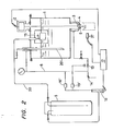
- the liquified inert gas dropping apparatus comprises a liquified inert gas storage tank 1 which is insulated by a heat insulating material (such as foamed styrene) or the like.
- the tank is provided with a dropping valve 3 such as a needle valve or a rotary valve or the like for adjusting the quantity of liquified gas dropped from the valve 3. This adjustment is by means of an electromagnetically-driven device 2 and a nozzle plate 4.
- the internal surfaces of the storage tank 1 are teflon-coated so that when the liquified inert gas is initially fed from a main tank 5, abrupt vaporization and pressure rise are restrained till the temperature of the storage tank 1 is sufficiently reduced to stabilize the internal pressure of the tank, thus shortening the liquid feed preparation time and saving liquified gas.
- the nozzle plate 4 is provided in a central portion thereof with a dropping nozzle 6 for producing drops of liquified gas, the whole structure thereof being formed of a resin material (for example, the material known as DAIFLON (TM)) to prevent a frost being deposited on the surface and to prevent the nozzle portion from freezing.
- a resin material for example, the material known as DAIFLON (TM)
- the vaporized gases in a space 7 in the upper portion of the storage tank 1 are conveyed to the outer peripheral portion of the nozzle plate 4 through a discharge pipeline system 8 and are discharged through a gas nozzle 9 so that the drops of liquified gas are shielded by a low temperature inert gas thus preventing the liquified gas from being vaporized and frozen.
- the vaporized gas is fed into the electromagnetically-driven device 2 through a vaporized gas guide port 10 to cool a solenoid 11, thus preventing overheating.
- the discharge pipeline system 8 is provided with an internal pressure regulating valve 13 and a safety valve 14 to regulate the internal pressure of the storage tank 1.
- Surplus gases are guided from a separate pipeline system (not shown) to a seamer rolling section and are there utilized gases as gases introduced into cans to reduce the amount of air sealed into the cans.
- a liquid gas feed into the storage tank 1 is provided with a bucket or ball type float valve 15 to that the opening of the valve is automatically adjusted by the liquid level to maintain the liquid level constant, thus stabilizing the liquid level and allowing liquid gas to be fed continuously. Since the bucket or ball type float valve 15 operates irrespective of any change in the desired pressure within the storage tank 1, the gas pressure within the storage tank 1 must be- controlled to save effectively the gases.
- a heater for maintaining in-tank pressure is provided and a control device 17 is actuated to maintain the internal pressure of the storage tank above a preset value by activating said heater to vaporize the liquified gas.
- the internal pressure regulating valve 13 is open to let said vaporized gases escape continuously to ensure that the internal pressure of the storage tank 1 does not rise above the preset value.
- the main tank 5 is provided with an anti-freezing heater 18 and a pressure regulating valve 19 for setting the internal pressure of the main tank 5.
- a pipeline system 20 connects the main tank 5 to the storage tank 1.
- the internal pressure regulating valve 13 is set to give a predetermined rate of production of drops and the pressure regulating valve 19 is set so that when the internal pressure of the main tank 5 is higher than the internal pressure of the storage tank 1 (as determined by the valve 13), liquified inert gas flows into the storage tank 1 through the pipeline system 20 under the pressure of the gas in main tank 5.
- the bucket or ball type float valve 15 stops inflow of liquified gas, after which the liquid level is maintained irrespective of any change in the internal pressure of the storage tank 1 below the internal pressure of the main tank 5, thus compensating automatically for the consumption of the liquified gas.
- FIG. 2 the structure of the liquified gas dropping apparatus shown in Fig. 2 is substantially the same as the embodiment of Fig. 1, like reference numerals designating like or corresponding parts.
- a quick charge pipe 20' is provided coaxial with the discharge pipe to speed up the intial feed of liquid gas to the storage tank 1.
- the internal pressure of the storage tank 1 is not maintained by a heater but by use of an internal pressure of the main tank 5 which is higher than the internal pressure of the storage tank 1.
- the main tank 5 is connected to the discharge pipeline 8 through a regulator 16', so that when the internal pressure of the storage tank decreases, the pressure in the storage tank is raised from the discharge pipeline.
- the internal pressure of the main tank 5 is maintained constant by a pressure control regulator 19'.
- the discharge gases from the main tank 5 merge with the discharge gases from the storage tank 1 and are fed as shield gases through the gas nozzle 9.
- a sensor 37 for sensing the presence of cans into which the liquified gas is dropped.
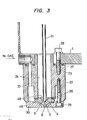
- Fig. 3 is an enlarged view of a dropping valve 3 and a nozzle plate 4.
- a valve rod 21 is formed with a needle-like end for the dropping valve 3, the other end thereof being connected to the solenoid 11.
- a TEFLON (TM)-coated block 22 has a gas passage 23 provided around an outer peripheral portion thereof, for the passage of vaporized gas from the discharge pipeline system 8 to the gas nozzle 9.
- the block 22 also has a storage chamber 24 provided in a central portion thereof and in communication with the liquified gas in the storage tank 1.
- 0-rings 25, 26 of resin for example, known as DAIFLON (TM)
- a bolt 28 for securing the block 22 to the storage tank 1 and a bolt 29 for securing a gas nozzle part 30 to the block 22 are provided.
- the needle-like end of the valve rod 21 is inserted into a central portion in an upper surface of the nozzle plate 4 to provide a needle valve.
- Communicating holes 49 for supplying liquified gas from storage chamber 24 to the nozzle are provided in the periphery of a hole 48 serving as a guide for the valve rod 21 on opening and closure of the valve.
- F ig. 4 shows an embodiment in which the needle valve 21' at the lower end of the valve rod 21 is formed separately from the valve rod 21.
- the right half-portion shows the valve rod 21 is moved down to close the valve, whereas the left half-portion thereof shows the valve rod 21 moved up to open the valve so that the liquified gas passes through the communicating hole 49 and drops from the nozzle 6.
- a push-up spring 21" is provided to allow the needle valve 21' to move upwardly with the valve rod 21.
- valve rod 21 is formed separately from the needle valve 21' as described above, there is the advantage that the needle valve 21' may be readily centred with the valve seat.
- Fig. 5 shows another embodiment of the nozzle plate 4' formed in an outer peripheral portion, on the lower end thereof, with tapped slots 32 for the detachable mounting of a pressure erasing nozzle 31 shown in F ig. 6.
- the pressure erasing nozzle 31 is provided to prevent uneveness in the quantity of liquid gas dropped as a result of the liquified gases impinging upon and scattering from the surfaces of the liquid within the can.
- the pressure erasing nozzle is formed of a sintered alloy and has an upper opening 33 formed with tapped slots 34 for engagement with the tapped slots 32 of the nozzle plate 4'.
- a tapered portion 35 forms a porous filter of an average pore diameter of 2 - 10 ⁇ and being liquid permeable, said tapered portion being of a sintered alloy and having a conductor 36 at the lower end thereof.
- Fig. 7 shows a control circuit A for the drops of liquified inert gas.
- the circuit includes a can sensor 37 for sensing the passage of can to produce a sensed signal, the sensor comprising a phototube and a proximity switch.
- the signal sensed by the can sensor 37 is differentiated by a differenciating circuit 38 and fed to a flip-flop circuit 39.
- the flip-flop circuit 39 is connected to the electromagnetically-driven device 2 and a counter 40, which is connected to a setter 41, an oscillator 42 and a timer 43.
- a change-over switch 44 is provided for selecting continuous. opening or intermittent opening of the dropping valve 3.
- the adjustment of the amount of liquified gases dropped is carried out by controlling the internal pressure of the storage tank 1 to be a particular constant value by use of the control device 17, by setting the setter 41 of the control circuit A to a predetermined time and by adjusting the time during which the dropping valve is open.
- control is by switching the switch 44 of the control circuit A to 'continuous-open' so that the dropping valve 3 is continuously open.
- adjustment of dropping quantity is by controlling the internal pressure of the storage tank 1 and by the use of a nozzle plate 4' of a suitable nozzle diameter and of the pressure erasing nozzle 31.
- the internal pressure of each can when filled with liquified gas, is measured by a can internal-pressure detector 45 (Fig. 1), and the dropping quantity of liquified gas adjusted by feed-back of the measured value.
- Figs. 8 and 9 show a modified nozzle for decreasing the flow speed of the liquified gas.
- the nozzle plate shown in Fig. 8 is substantially the same as that shown in Fig. 3 except for the provision of an outlet 62 positioned at the lower part of the nozzle 6.
- the outlet has an impinging surface 61 inclined with respect to the outlet so that the liquified gas which flows down through the nozzle 6 impinges upon the impinging surface 61 and loses kinetic energy, thus lowering its outflow speed.
- the noz-outlet has a nozzle pipe 71, which is positioned eccentrically with respect to the outlet 72 so that the liquified gas initially impinges upon the upper end of the nozzle pipe 71 to lose kinetic energy, after which it flows down through the nozzle pipe 71.
Landscapes
- Engineering & Computer Science (AREA)
- Mechanical Engineering (AREA)
- General Engineering & Computer Science (AREA)
- Vacuum Packaging (AREA)
- Filling Or Discharging Of Gas Storage Vessels (AREA)
Applications Claiming Priority (4)
| Application Number | Priority Date | Filing Date | Title |
|---|---|---|---|
| JP56140252A JPS5842900A (ja) | 1981-09-08 | 1981-09-08 | 液化ガス滴下装置 |
| JP140252/81 | 1981-09-08 | ||
| JP56185510A JPS5888299A (ja) | 1981-11-20 | 1981-11-20 | 液化ガス滴下装置 |
| JP185510/81 | 1981-11-20 |
Publications (2)
| Publication Number | Publication Date |
|---|---|
| EP0074702A2 true EP0074702A2 (fr) | 1983-03-23 |
| EP0074702A3 EP0074702A3 (fr) | 1983-11-16 |
Family
ID=26472836
Family Applications (1)
| Application Number | Title | Priority Date | Filing Date |
|---|---|---|---|
| EP82302931A Withdrawn EP0074702A3 (fr) | 1981-09-08 | 1982-06-08 | Dispositif pour le dégouttement d'un gaz inerte liquéfié dans une boíte |
Country Status (3)
| Country | Link |
|---|---|
| US (1) | US4489767A (fr) |
| EP (1) | EP0074702A3 (fr) |
| KR (1) | KR840000761A (fr) |
Cited By (5)
| Publication number | Priority date | Publication date | Assignee | Title |
|---|---|---|---|---|
| EP0090337A3 (fr) * | 1982-03-26 | 1984-05-16 | Teisan Kabushiki Kaisha | Méthode de prévention de pénétration de l'air dans un réservoir isolé |
| DE3419855A1 (de) * | 1983-05-30 | 1984-12-06 | L'Air Liquide, S.A. pour l'Etude et l'Exploitation des Procédés Georges Claude, Paris | Vorrichtung zur abgabe eines ununterbrochenen strahles einer cryogenen fluessigkeit |
| GB2169998A (en) * | 1985-01-18 | 1986-07-23 | Metal Box Plc | Liquid nitrogen metering device with nozzle of insulating material |
| GB2235759A (en) * | 1989-09-04 | 1991-03-13 | Guinness Son & Co Ltd A | Liquid dispensing system and packaging apparatus |
| KR101985262B1 (ko) * | 2018-10-25 | 2019-06-04 | 주식회사 동신켐텍 | 브롬액화가스 보관용 탱크 작동방법 |
Families Citing this family (23)
| Publication number | Priority date | Publication date | Assignee | Title |
|---|---|---|---|---|
| US4662154A (en) * | 1984-10-12 | 1987-05-05 | Continental Can Company, Inc. | Liquid inert gas dispenser and control |
| US4750314A (en) * | 1986-01-13 | 1988-06-14 | American National Can Company | Method for propellant filling and sealing of a container |
| US4658979A (en) * | 1986-01-13 | 1987-04-21 | American Can Company | Propellant filling and sealing valve |
| SE457750B (sv) * | 1986-07-21 | 1989-01-23 | Aga Ab | Apparat foer dosering av smaa maengder kondenserad gas |
| US4865088A (en) * | 1986-09-29 | 1989-09-12 | Vacuum Barrier Corporation | Controller cryogenic liquid delivery |
| US4715187A (en) * | 1986-09-29 | 1987-12-29 | Vacuum Barrier Corporation | Controlled cryogenic liquid delivery |
| NL8603176A (nl) * | 1986-12-12 | 1988-07-01 | Calumatic Bv | Werkwijze en inrichting voor het verlagen van de hoeveelheid zuurstof in de ruimte boven de vulling binnen een houder. |
| US4880041A (en) * | 1987-04-15 | 1989-11-14 | Tokyo Seikan Kaisha, Ltd. | Apparatus for flowing and filling liquified inert gas |
| DK164274C (da) * | 1987-10-23 | 1992-10-19 | Neste Oy | Fremgangsmaade til at foere en gas eller vaeske, hvis temperatur er lavere end temperaturen i en underjordisk beholder, frem til den underjordiske beholder samt et foederoersaggregat til beholderen til brug ved udoevelse af fremgangsmaaden. |
| US4947650A (en) * | 1989-09-08 | 1990-08-14 | Vacuum Barrier Corporation | Method and apparatus for liquid cryogen pressurization of containers of particulates |
| US5033254A (en) * | 1990-04-19 | 1991-07-23 | American National Can Company | Head-space calibrated liquified gas dispensing system |
| FR2696152B1 (fr) * | 1992-09-29 | 1994-10-28 | Air Liquide | Procédé et dispositif de distribution de doses de liquide, notamment de gaz liquéfié. |
| US5301723A (en) * | 1992-11-06 | 1994-04-12 | Hydra Rig, Inc. | Apparatus and method of preventing ice accumulation on coupling valves for cryogenic fluids |
| US5415313A (en) * | 1994-02-14 | 1995-05-16 | Sang-Seo; Hong | Can |
| US5385025A (en) * | 1994-03-04 | 1995-01-31 | Mg Industries | Apparatus and method for dispensing droplets of a cryogenic liquid |
| AU3344199A (en) * | 1998-04-17 | 1999-11-08 | Toyo Seikan Kaisha Ltd. | Method and device for manufacturing positive pressure packaging body |
| US6182715B1 (en) | 2000-01-18 | 2001-02-06 | Alex R. Ziegler | Liquid nitrogen injection system with flexible dosing arm for pressurization and inerting containers on production lines |
| DE10119115A1 (de) * | 2001-04-19 | 2002-10-31 | Messer Griesheim Gmbh | Druckbehälter |
| KR20040031557A (ko) * | 2002-11-25 | 2004-04-13 | 강호철 | 환자용 침대 |
| WO2005121633A1 (fr) * | 2004-06-11 | 2005-12-22 | Air Liquide Deutschland Gmbh | Remplissage cryogenique assiste de recipients sous pression |
| US20060010886A1 (en) * | 2004-07-14 | 2006-01-19 | Clamage Eric D | Liquid cryogen dosing system with nozzle for pressurizing and inerting containers |
| US7562631B2 (en) * | 2007-09-19 | 2009-07-21 | Cnh America Llc | Crop residue and soil conditioning agricultural implement |
| WO2014060320A1 (fr) * | 2012-10-15 | 2014-04-24 | V.B.S. | Appareil doseur de dioxyde de carbone |
Family Cites Families (4)
| Publication number | Priority date | Publication date | Assignee | Title |
|---|---|---|---|---|
| US3670786A (en) * | 1970-06-02 | 1972-06-20 | American Home Prod | Container filling apparatus |
| AU505044B2 (en) * | 1975-12-01 | 1979-11-08 | Flex Pack Service and Supplies Pty Ltd | Liquid fill apparatus |
| DE2732318C2 (de) * | 1977-07-16 | 1986-06-26 | Messer Griesheim Gmbh, 6000 Frankfurt | Vorrichtung zum Dosieren kleiner Mengen eines tiefsiedenden verflüssigten Gases |
| CA1152041A (fr) * | 1980-12-18 | 1983-08-16 | Eric L. Jensen | Systeme de mise sous pression de contenants |
-
1982
- 1982-05-28 US US06/383,319 patent/US4489767A/en not_active Expired - Fee Related
- 1982-06-08 EP EP82302931A patent/EP0074702A3/fr not_active Withdrawn
- 1982-06-17 KR KR1019820002703A patent/KR840000761A/ko active Pending
Cited By (8)
| Publication number | Priority date | Publication date | Assignee | Title |
|---|---|---|---|---|
| EP0090337A3 (fr) * | 1982-03-26 | 1984-05-16 | Teisan Kabushiki Kaisha | Méthode de prévention de pénétration de l'air dans un réservoir isolé |
| DE3419855A1 (de) * | 1983-05-30 | 1984-12-06 | L'Air Liquide, S.A. pour l'Etude et l'Exploitation des Procédés Georges Claude, Paris | Vorrichtung zur abgabe eines ununterbrochenen strahles einer cryogenen fluessigkeit |
| US4546609A (en) * | 1983-05-30 | 1985-10-15 | L'air Liquide, Societe Anonyme Pour L'etude Et L'exploitation Des Procedes Georges Claude | Apparatus for providing a continuous stream of a cryogenic liquid and in particular liquid nitrogen |
| GB2169998A (en) * | 1985-01-18 | 1986-07-23 | Metal Box Plc | Liquid nitrogen metering device with nozzle of insulating material |
| GB2235759A (en) * | 1989-09-04 | 1991-03-13 | Guinness Son & Co Ltd A | Liquid dispensing system and packaging apparatus |
| EP0421597A1 (fr) * | 1989-09-04 | 1991-04-10 | ARTHUR GUINNESS SON & COMPANY (DUBLIN) LIMITED | Système de distribution de liquide et dispositif d'emballage comprenant le système |
| AU625140B2 (en) * | 1989-09-04 | 1992-07-02 | Arthur Guinness Son & Company (Dublin) Limited | A liquid dispensing system and packaging apparatus which includes such a system |
| KR101985262B1 (ko) * | 2018-10-25 | 2019-06-04 | 주식회사 동신켐텍 | 브롬액화가스 보관용 탱크 작동방법 |
Also Published As
| Publication number | Publication date |
|---|---|
| KR840000761A (ko) | 1984-02-27 |
| EP0074702A3 (fr) | 1983-11-16 |
| US4489767A (en) | 1984-12-25 |
Similar Documents
| Publication | Publication Date | Title |
|---|---|---|
| EP0074702A2 (fr) | Dispositif pour le dégouttement d'un gaz inerte liquéfié dans une boîte | |
| US4588000A (en) | Method and apparatus for metering and dispensing volatile liquids | |
| US4059424A (en) | Apparatus for the controlled supply of cryogenic fluid | |
| US4192147A (en) | Arrangements for the controlled injection of cryogenic fluid | |
| DE69734823T2 (de) | Kontrollierte dosierung von flüssigem kältemittel | |
| US3501097A (en) | Powder feed device for flame spray guns | |
| AU631049B2 (en) | Cryogen delivery apparatus | |
| JPH0582269B2 (fr) | ||
| JPH0135240B2 (fr) | ||
| US3460555A (en) | Pressure regulator construction | |
| US4586343A (en) | Process and device for metering small amounts of a low boiling liquified gas | |
| US5385025A (en) | Apparatus and method for dispensing droplets of a cryogenic liquid | |
| AU687268B2 (en) | Process and device for the preparation of a gaseous mixture comprised by a vector gas and a vaporized additive | |
| US5566733A (en) | Apparatus for delivering, at high frequency, measured quantities of liquid | |
| US2936326A (en) | Method and apparatus for pressure metal dispensing | |
| US1942944A (en) | Method and apparatus for dispensing gas material | |
| KR900000265B1 (ko) | 음료혼합장치 | |
| US4225537A (en) | Carbonating device | |
| US5018358A (en) | Cryogen delivery apparatus | |
| US4796434A (en) | Apparatus for delivering a measured amount of a low-boiling liquefied gas | |
| JPS5833439B2 (ja) | 不活性液化ガス定量滴下法および装置 | |
| JPH0159170B2 (fr) | ||
| JPS6152356B2 (fr) | ||
| US3379344A (en) | Apparatus for treating and handling a beverage | |
| JPH11292018A (ja) | 液体窒素の微小粒滴化方法及びその装置、該装置のノズル組立体並びに液体窒素微小粒滴充填による陽圧包装体の製造方法 |
Legal Events
| Date | Code | Title | Description |
|---|---|---|---|
| PUAI | Public reference made under article 153(3) epc to a published international application that has entered the european phase |
Free format text: ORIGINAL CODE: 0009012 |
|
| AK | Designated contracting states |
Designated state(s): DE FR GB |
|
| PUAL | Search report despatched |
Free format text: ORIGINAL CODE: 0009013 |
|
| AK | Designated contracting states |
Designated state(s): DE FR GB |
|
| 17P | Request for examination filed |
Effective date: 19840425 |
|
| STAA | Information on the status of an ep patent application or granted ep patent |
Free format text: STATUS: THE APPLICATION IS DEEMED TO BE WITHDRAWN |
|
| 18D | Application deemed to be withdrawn |
Effective date: 19870930 |
|
| RIN1 | Information on inventor provided before grant (corrected) |
Inventor name: YAMADA, MORIO |