EP0074785A2 - Support de moteur - Google Patents
Support de moteur Download PDFInfo
- Publication number
- EP0074785A2 EP0074785A2 EP82304695A EP82304695A EP0074785A2 EP 0074785 A2 EP0074785 A2 EP 0074785A2 EP 82304695 A EP82304695 A EP 82304695A EP 82304695 A EP82304695 A EP 82304695A EP 0074785 A2 EP0074785 A2 EP 0074785A2
- Authority
- EP
- European Patent Office
- Prior art keywords
- motor
- mounting
- support frame
- ears
- support plate
- Prior art date
- Legal status (The legal status is an assumption and is not a legal conclusion. Google has not performed a legal analysis and makes no representation as to the accuracy of the status listed.)
- Withdrawn
Links
- 210000005069 ears Anatomy 0.000 claims abstract description 11
- 230000003534 oscillatory effect Effects 0.000 description 2
- 229910000831 Steel Inorganic materials 0.000 description 1
- 238000004378 air conditioning Methods 0.000 description 1
- -1 e.g. Substances 0.000 description 1
- 239000012717 electrostatic precipitator Substances 0.000 description 1
- 238000002955 isolation Methods 0.000 description 1
- 239000000463 material Substances 0.000 description 1
- 239000002184 metal Substances 0.000 description 1
- 238000000034 method Methods 0.000 description 1
- 239000012858 resilient material Substances 0.000 description 1
- 239000010959 steel Substances 0.000 description 1
- 239000000725 suspension Substances 0.000 description 1
- 238000003466 welding Methods 0.000 description 1
Images


Classifications
-
- H—ELECTRICITY
- H02—GENERATION; CONVERSION OR DISTRIBUTION OF ELECTRIC POWER
- H02K—DYNAMO-ELECTRIC MACHINES
- H02K5/00—Casings; Enclosures; Supports
- H02K5/24—Casings; Enclosures; Supports specially adapted for suppression or reduction of noise or vibrations
-
- F—MECHANICAL ENGINEERING; LIGHTING; HEATING; WEAPONS; BLASTING
- F16—ENGINEERING ELEMENTS AND UNITS; GENERAL MEASURES FOR PRODUCING AND MAINTAINING EFFECTIVE FUNCTIONING OF MACHINES OR INSTALLATIONS; THERMAL INSULATION IN GENERAL
- F16F—SPRINGS; SHOCK-ABSORBERS; MEANS FOR DAMPING VIBRATION
- F16F1/00—Springs
- F16F1/36—Springs made of rubber or other material having high internal friction, e.g. thermoplastic elastomers
- F16F1/373—Springs made of rubber or other material having high internal friction, e.g. thermoplastic elastomers characterised by having a particular shape
- F16F1/3732—Springs made of rubber or other material having high internal friction, e.g. thermoplastic elastomers characterised by having a particular shape having an annular or the like shape, e.g. grommet-type resilient mountings
-
- F—MECHANICAL ENGINEERING; LIGHTING; HEATING; WEAPONS; BLASTING
- F16—ENGINEERING ELEMENTS AND UNITS; GENERAL MEASURES FOR PRODUCING AND MAINTAINING EFFECTIVE FUNCTIONING OF MACHINES OR INSTALLATIONS; THERMAL INSULATION IN GENERAL
- F16M—FRAMES, CASINGS OR BEDS OF ENGINES, MACHINES OR APPARATUS, NOT SPECIFIC TO ENGINES, MACHINES OR APPARATUS PROVIDED FOR ELSEWHERE; STANDS; SUPPORTS
- F16M7/00—Details of attaching or adjusting engine beds, frames, or supporting-legs on foundation or base; Attaching non-moving engine parts, e.g. cylinder blocks
Definitions
- the present invention relates to motor mountings.
- Motor driven fans used in many ventiling and air conditioning devices often include a direct driven fan mounted on a motor shaft, a motor supporting frame and a panel or fan housing to which the frame is fastened.
- the panel and frame conventionally have an opening to accommodate the fan with the apparatus being mounted in an opening of an enclosure served by the apparatus, e.g., air conditioner, electrostatic precipitator, etc. While such a fan apparatus often involves attempts to secure a balance of the rotating parts, e.g., the fan and motor armature, those ventiling devices are frequently noisy in operation due mainly to vibration and oscillatory effects in the motor, fan, support frame and panel occasioned by the rapidly rotating and oscillatory parts.
- An aim of the present invention is to provide a motor mounting having improved vibration isolating capabilities.
- a motor mounting comprising a motor support plate attached to'the motor in a plane generally at right angles to the motor drive shaft, a motor support frame, and mounting devices for mounting the support plate on the support frame, characterized in that each mounting device is provided by a unitary member having two legs each terminating at its free end in a respective one of two ears extending generally at right angles to the main portion of its respective leg, in that one of the ears of each device is secured to the motor support plate and in that the other of the ears is resiliently mounted on the motor support frame.
- FIG. 1 there is shown a side view of a motor mounting supporting an electrical motor 2 having a motor drive shaft 4 which may be-connected to a motor drive apparatus by any suitable means (not shown).
- the motor 2 is connected by electrical wires 6 to a conventional means for energizing the electrical motor 2.
- a motor support plate 18 is mounted on one end of the motor 2 generally perpendicular to the rotational axis of the motor drive shaft 4 and from which extends a plurality of mounting devices 10, 12, 14 and 16.
- the motor support plate 18 is connected to the motor 2 by a plurality of machine screws each extending longitudinally from the motor 2 through the support plate 8 and fastened to the support plate 8 by a respective one of a plurality of nuts 20.
- Each of the mounting devices 10, 12, 14 and 16 is of a two-legged shape and one of the legs 18 is attached to the periphery of the support plate 8 either by welding or other conventional securing means or by being integrally formed therewith by a suitable metal stamping process with a subsequent forming of the legs 10, 12, 14 and 16.
- the end of the attached leg 18 of each of device 10, 12, 14 and 16 is provided by an ear 24 extending at right angles from the main portion of the leg.
- the ear 24 is utilized to position the corresponding leg of the respective motor mounting at substantially a right angle with respect to the plane of the support plate 8.
- each of the leg 19 of mounting devices 10, 12, 14 and 16 is terminated in a ear 25, extending at right angles to the main portion of the leg; ear 25 having a hole 26 therein to permit attachment of the mounting devices of support plate 8.
- the main leg portions are generally parallel and separated by elongate slot 50. In use, the main leg portions of the mounting devices 10, 12, 14 and 16 extend from the support plate 8 generally parallel to the rotational axis of the motor 2, and the mounting devices 10, 12, 14 and 16 allow any angular vibration of the motor 2 to be isolated from a support frame.
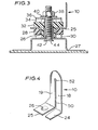
- FIG. 3 there is shown a cross-sectional view of the ear 25 on the mounting device 10 as attached to a support frame 27.
- the support frame 27 is arranged as a hollow box section which is separated from the ear 25 by a layered arrangement of a resilient ring 28 in contact with the ear 25 and a first spacing washer 30 between the resilient ring 28 and the mounting frame 27.
- a resilient bushing 32 is positioned in contact with the other side of the ear 25 from the ring 28 and includes a coaxial cylindrical extension extending through the hole 26 in the ear 25 to the mounting frame 27.
- a second spacing washer 34 is positioned on top of the resilient bushing 32 and is in contact with a thrust washer 36.
- a nut 38 and lock washer 40 are located on the other side of the thrust washer 36 from the spacing ring 34 and are mounted on the threaded end of a floating pin 42.
- the pin 42 has a head 44 at one end thereof located within the hollow frame 27 and overlying the hole 26 whereby the pin 42 serves as a guide for the rubber bushing 32 and thrust washer 36.
- the resilient bushing 32 and the resilient ring 28 are effective to resiliently mount the device on the support frame, the pin 42 allowing a degree of movement of the ear 25 and the bushing 32 to provide vibration isolation.
- the ring 28 and 32 may be made of any suitable resilient material, e.g., rubber.
- the legs 18, 19 of the device as mentioned previously are separated by elongate slot 50 and this slot terminates at its closed end in an enlarged hole 52.
- the ears 24 and 25 may be either substantially coplanar or non-coplanar to afford a desired mounting of the motor 2.on the plate 8 and the support frame 27.
- the device may be made of any suitable material having a suitable resiliency and strength, e.g., spring type steel having a thickness of approximately 1 mm.
Landscapes
- Engineering & Computer Science (AREA)
- General Engineering & Computer Science (AREA)
- Mechanical Engineering (AREA)
- Power Engineering (AREA)
- Motor Or Generator Frames (AREA)
Applications Claiming Priority (2)
| Application Number | Priority Date | Filing Date | Title |
|---|---|---|---|
| US301630 | 1981-09-14 | ||
| US06/301,630 US4452417A (en) | 1981-09-14 | 1981-09-14 | Vibration isolating motor mount |
Publications (2)
| Publication Number | Publication Date |
|---|---|
| EP0074785A2 true EP0074785A2 (fr) | 1983-03-23 |
| EP0074785A3 EP0074785A3 (fr) | 1983-08-17 |
Family
ID=23164187
Family Applications (1)
| Application Number | Title | Priority Date | Filing Date |
|---|---|---|---|
| EP82304695A Withdrawn EP0074785A3 (fr) | 1981-09-14 | 1982-09-08 | Support de moteur |
Country Status (4)
| Country | Link |
|---|---|
| US (1) | US4452417A (fr) |
| EP (1) | EP0074785A3 (fr) |
| JP (1) | JPS58103846A (fr) |
| CA (1) | CA1185582A (fr) |
Cited By (2)
| Publication number | Priority date | Publication date | Assignee | Title |
|---|---|---|---|---|
| EP0521798A1 (fr) * | 1991-07-05 | 1993-01-07 | Ecia - Equipements Et Composants Pour L'industrie Automobile | Support métallique perfectionné, procédé pour sa confection et son application aux moteurs électriques |
| WO2012069201A3 (fr) * | 2010-11-25 | 2012-07-19 | Avl List Gmbh | Dispositif de production de courant, en particulier prolongateur d'autonomie pour un véhicule automobile |
Families Citing this family (25)
| Publication number | Priority date | Publication date | Assignee | Title |
|---|---|---|---|---|
| US4648579A (en) * | 1985-06-10 | 1987-03-10 | Wilson John D | Cushioned mounting arrangement for a motor housing |
| US4858880A (en) * | 1987-05-29 | 1989-08-22 | Caterpillar Inc. | Resilient load supporting and motion accommodating mounting apparatus |
| US5112024A (en) * | 1988-08-22 | 1992-05-12 | White Consolidated Industries, Inc. | Modular room air conditioner and method for making same |
| US5348267A (en) * | 1992-09-18 | 1994-09-20 | Eaton Corporation | Apparatus for isolating a sensor |
| GB2284246B (en) * | 1993-10-28 | 1998-04-29 | Showa Electric Wire & Cable Co | Vibration isolator for motor |
| US5449153A (en) * | 1993-12-13 | 1995-09-12 | Cadillac Rubber & Plastics, Inc. | Isolation mounting plate for blower motor |
| JPH0826100A (ja) * | 1994-07-13 | 1996-01-30 | Sumitomo Electric Ind Ltd | 車両用ブレーキ液圧制御装置 |
| US5959379A (en) * | 1998-03-20 | 1999-09-28 | General Electric Company | Vibration-isolation grommet and motor assembly containing same |
| DE19936178A1 (de) * | 1999-07-31 | 2001-02-01 | Mulfingen Elektrobau Ebm | Anordnung zur schwingungsisolierenden Halterung eines Elektromotors |
| US6357247B1 (en) * | 2001-05-16 | 2002-03-19 | Carrier Corporation | Fan motor mount |
| US7255318B2 (en) * | 2001-12-21 | 2007-08-14 | General Electric Company | Stud mounting system |
| US20050040576A1 (en) * | 2003-08-20 | 2005-02-24 | Ernest Oxenknecht | Multi-axis isolator and assembly for the same |
| JP4465202B2 (ja) * | 2004-02-06 | 2010-05-19 | Hoya株式会社 | モータの制振取付構造 |
| US7301253B2 (en) * | 2005-05-16 | 2007-11-27 | S&S Marketing, Inc. | Vehicle electric fan motor with universal mount |
| US8002528B2 (en) * | 2006-09-18 | 2011-08-23 | Emerson Climate Technologies, Inc. | Compressor assembly having vibration attenuating structure |
| JP5007693B2 (ja) * | 2008-03-11 | 2012-08-22 | 日産自動車株式会社 | 電動機、電動機支持部材および電動機支持方法 |
| CN101922785B (zh) * | 2009-06-09 | 2014-04-30 | 乐金电子(天津)电器有限公司 | 柜式空调室内机送风电机的固定结构 |
| JP5343864B2 (ja) * | 2010-01-06 | 2013-11-13 | 株式会社島津製作所 | 送液ポンプ |
| US8876092B2 (en) * | 2012-10-19 | 2014-11-04 | Lennox Industries, Inc. | Motor mounting assembly with tunable vibration and noise reduction capabilities |
| JP6282916B2 (ja) * | 2014-04-10 | 2018-02-21 | 山洋電気株式会社 | 冷却ファンの取付構造 |
| DE102016204881A1 (de) * | 2015-04-08 | 2016-10-13 | Mahle International Gmbh | Gebläseeinrichtung |
| US10215270B2 (en) | 2015-09-14 | 2019-02-26 | Gpcp Ip Holdings Llc | Automated product dispensers and related methods for isolating a drive assembly to inhibit vibration transmission |
| CA2955055C (fr) | 2017-01-17 | 2020-08-11 | Alwin Manufacturing Co., Inc. | Distributeur dote d'un attenuateur de bruit |
| WO2020049617A1 (fr) * | 2018-09-03 | 2020-03-12 | 本田技研工業株式会社 | Unité d'alimentation électrique, et machine de travail |
| DE102021122505B3 (de) * | 2021-08-31 | 2022-12-22 | Nidec Gpm Gmbh | Kraftfahrzeug-Kühlsystem mit einer elektrischen Kühlmittelpumpe |
Family Cites Families (22)
| Publication number | Priority date | Publication date | Assignee | Title |
|---|---|---|---|---|
| US30498A (en) * | 1860-10-23 | Ventilating millstones | ||
| US1935179A (en) * | 1930-08-25 | 1933-11-14 | Ilg Electric Ventilating Compa | Ventilating appliance |
| US2018180A (en) * | 1934-06-28 | 1935-10-22 | Williams Oil O Matic Heating | Resilient support |
| US2183372A (en) * | 1935-06-28 | 1939-12-12 | Thomas Hans | Hydraulic device |
| US2178401A (en) * | 1937-07-17 | 1939-10-31 | E A Lab Inc | Motor mounting |
| US2208532A (en) * | 1938-10-15 | 1940-07-16 | United Carr Fastener Corp | Nut member |
| US2301818A (en) * | 1940-11-06 | 1942-11-10 | B F Sturtevant Co | Resilient motor support |
| FR1107712A (fr) * | 1954-06-25 | 1956-01-04 | Suspension protectrice pour appareils sujets aux effets des vibrations et oscillations | |
| US3145910A (en) * | 1961-06-05 | 1964-08-25 | Nutone Inc | Spring mount for fan motor of ventilating equipment |
| GB1000205A (en) * | 1964-05-15 | 1965-08-04 | Bacho Ab | Suspension and vibration-damping device for fans |
| US3326503A (en) * | 1965-09-03 | 1967-06-20 | Falk Corp | Speed reducer mounting assembly |
| GB1195295A (en) * | 1967-12-08 | 1970-06-17 | Smiths Industries Ltd | Improvements in or relating to Centrifugal Fans and Blowers |
| US3506226A (en) * | 1968-06-25 | 1970-04-14 | Minnesota Mining & Mfg | Vibration isolating motor bracket |
| US3830595A (en) * | 1972-08-16 | 1974-08-20 | Tappan Co | Motor mounting support |
| US4161812A (en) * | 1975-12-01 | 1979-07-24 | General Electric Company | Methods of securing torsionally flexible motor mounting arrangements to supports therefor |
| US4200257A (en) * | 1975-12-01 | 1980-04-29 | General Electric Company | Torsional vibration isolating motor mounting system, mounting arrangement, assemblies including the same |
| US4076197A (en) * | 1976-06-18 | 1978-02-28 | General Electric Company | Torsional vibration isolating motor mounting arrangement and method of making the same |
| US4161667A (en) * | 1977-11-16 | 1979-07-17 | A. O. Smith Corporation | Flexible mounting of electric motors |
| JPS5495305A (en) * | 1978-01-13 | 1979-07-27 | Hitachi Ltd | Mounting device for mold-type motor |
| USRE30498E (en) | 1978-08-25 | 1981-01-27 | Truck-Lite Co., Inc. | Filament shock mounting for lamps |
| US4253634A (en) * | 1978-09-05 | 1981-03-03 | Emerson Electric Co. | Electric motor mounting system |
| US4293114A (en) * | 1978-10-10 | 1981-10-06 | A. O. Smith Corporation | Flexible motor mounting |
-
1981
- 1981-09-14 US US06/301,630 patent/US4452417A/en not_active Expired - Fee Related
-
1982
- 1982-07-14 CA CA000407215A patent/CA1185582A/fr not_active Expired
- 1982-09-08 EP EP82304695A patent/EP0074785A3/fr not_active Withdrawn
- 1982-09-14 JP JP57160764A patent/JPS58103846A/ja active Granted
Cited By (3)
| Publication number | Priority date | Publication date | Assignee | Title |
|---|---|---|---|---|
| EP0521798A1 (fr) * | 1991-07-05 | 1993-01-07 | Ecia - Equipements Et Composants Pour L'industrie Automobile | Support métallique perfectionné, procédé pour sa confection et son application aux moteurs électriques |
| FR2678709A1 (fr) * | 1991-07-05 | 1993-01-08 | Ecia Equip Composants Ind Auto | Support metallique perfectionne, procede pour sa confection et son application aux moteurs electriques. |
| WO2012069201A3 (fr) * | 2010-11-25 | 2012-07-19 | Avl List Gmbh | Dispositif de production de courant, en particulier prolongateur d'autonomie pour un véhicule automobile |
Also Published As
| Publication number | Publication date |
|---|---|
| JPS58103846A (ja) | 1983-06-21 |
| JPS638700B2 (fr) | 1988-02-24 |
| CA1185582A (fr) | 1985-04-16 |
| US4452417A (en) | 1984-06-05 |
| EP0074785A3 (fr) | 1983-08-17 |
Similar Documents
| Publication | Publication Date | Title |
|---|---|---|
| EP0074785A2 (fr) | Support de moteur | |
| CA2189942C (fr) | Appareil servant au montage d'un compresseur | |
| US4801270A (en) | Shaft mounting and electrical grounding device | |
| US3330515A (en) | Machine installation | |
| US5780952A (en) | Brush assembly for electric motor | |
| US5030068A (en) | Vibration and shock damping air blower | |
| CN106464074A (zh) | 用于振动隔绝的马达保持部的装置 | |
| US5798588A (en) | Vibrating motor, vibrating motor casing and vibrating device containing vibrating motor | |
| US4645361A (en) | End shield with cylindrical bearing mount | |
| US3506226A (en) | Vibration isolating motor bracket | |
| US4679761A (en) | Vibration dissipation mount for motors or the like | |
| US6102663A (en) | Suspension assemblies for ceiling fans | |
| EP0722544B1 (fr) | Dispositif d'amortissement des vibrations d'un rotor | |
| US6547208B2 (en) | Motor mounting assembly | |
| EP0363462A1 (fr) | Structure de montage pour moteur electrique. | |
| JPH0287952A (ja) | 小形電動機 | |
| JPH05196244A (ja) | 空気調和機の防振装置 | |
| RU2305358C2 (ru) | Опорное устройство сердечника статора | |
| KR100365917B1 (ko) | 전동모터 | |
| JPH038239B2 (fr) | ||
| JPH0268319A (ja) | 電動モータによって動かされる単独駆動機構を備えた精紡機用スピンドル | |
| JPS622901Y2 (fr) | ||
| JPH04217839A (ja) | 回転電機 | |
| US4488700A (en) | Motor support apparatus | |
| JPH04262098A (ja) | 羽根車の取付装置 |
Legal Events
| Date | Code | Title | Description |
|---|---|---|---|
| PUAI | Public reference made under article 153(3) epc to a published international application that has entered the european phase |
Free format text: ORIGINAL CODE: 0009012 |
|
| AK | Designated contracting states |
Designated state(s): BE DE FR GB NL SE |
|
| PUAL | Search report despatched |
Free format text: ORIGINAL CODE: 0009013 |
|
| AK | Designated contracting states |
Designated state(s): BE DE FR GB NL SE |
|
| 17P | Request for examination filed |
Effective date: 19840209 |
|
| 19U | Interruption of proceedings before grant |
Effective date: 19860217 |
|
| 19W | Proceedings resumed before grant after interruption of proceedings |
Effective date: 19860718 |
|
| STAA | Information on the status of an ep patent application or granted ep patent |
Free format text: STATUS: THE APPLICATION IS DEEMED TO BE WITHDRAWN |
|
| 18D | Application deemed to be withdrawn |
Effective date: 19910403 |
|
| RIN1 | Information on inventor provided before grant (corrected) |
Inventor name: KRAFTHEFER, BRIAN C. Inventor name: STRAND, ROLF L. |