EP0074796B1 - Enregistreurs sur bande vidéo - Google Patents
Enregistreurs sur bande vidéo Download PDFInfo
- Publication number
- EP0074796B1 EP0074796B1 EP82304724A EP82304724A EP0074796B1 EP 0074796 B1 EP0074796 B1 EP 0074796B1 EP 82304724 A EP82304724 A EP 82304724A EP 82304724 A EP82304724 A EP 82304724A EP 0074796 B1 EP0074796 B1 EP 0074796B1
- Authority
- EP
- European Patent Office
- Prior art keywords
- video tape
- rotary
- tape recorder
- magnetic head
- laser element
- Prior art date
- Legal status (The legal status is an assumption and is not a legal conclusion. Google has not performed a legal analysis and makes no representation as to the accuracy of the status listed.)
- Expired
Links
Images


Classifications
-
- G—PHYSICS
- G11—INFORMATION STORAGE
- G11B—INFORMATION STORAGE BASED ON RELATIVE MOVEMENT BETWEEN RECORD CARRIER AND TRANSDUCER
- G11B15/00—Driving, starting or stopping record carriers of filamentary or web form; Driving both such record carriers and heads; Guiding such record carriers or containers therefor; Control thereof; Control of operating function
- G11B15/02—Control of operating function, e.g. switching from recording to reproducing
- G11B15/12—Masking of heads; circuits for Selecting or switching of heads between operative and inoperative functions or between different operative functions or for selection between operative heads; Masking of beams, e.g. of light beams
- G11B15/14—Masking or switching periodically, e.g. of rotating heads
Definitions
- This invention relates to video tape recorders (VTRs).
- a magnetic head is mounted on a rotary drum in a known helical scan type VTR, and video signals are transmitted through a rotary transformer to and from the magnetic head.
- Figure 1 of the accompanying drawings shows one example of a rotary transformer 1.
- a rotary core 3 is arranged around a stationary core 2.
- a plurality of grooves 4 and 5 are formed in the cores 2 and 3, respectively, facing each other.
- Coils 6 and 7 are mounted in . the grooves 4 and 5, respectively.
- the rotary core 3 is fixed on the rotary drum (not shown) of the VTR, and rotates therewith.
- the coils 7 are connected to the magnetic heads which are mounted on the rotary drum.
- the coils 6 mounted in the stationary core 2 are selectively connected through a change-over switch to a recording circuit and a reproducing circuit in the VTR.
- the video signals are transmitted by the rotary transformer 1 to and from the magnetic heads in the known VTR, but the following problems may arise.
- a signal can be transmitted optically to and from a rotary magnetic head using luminous diodes, as disclosed for example in Patent Abstracts of Japan, Vol. 2, No. 56, 24 April 1978, page 14 92 E 78.
- US-A-3 823 276 that mirrors and lenses can be used in an optical path in a recording and reproducing system.
- -French patent specification FR-A-2 472 243 shows a laser diode used in an optical recording device to provide a writing laser beam.
- a video tape recorder comprising:
- a rotational side circuit 11 mounted on a rotary drum (not shown) of the VTR comprises a magnetic head 9, a capacitor C, a laser diode LD and a current source 10.
- a coil 8 is wound on the magnetic head 9, and is connected to the capacitor C and to the laser diode LD.
- the current source 10 supplies a constant current I LD .
- a lens 12 is arranged near the laser diode LD.
- a photoelectric conversion element such as a photo- diode PD and a reproducing amplifier 13 are arranged on a stationary part of the VTR.
- a lens 15 is arranged near the photodiode PD.
- signals are reproduced from the magnetic head 9 contacting a magnetic tape (not shown) in the reproducing mode of the VTR, when the rotary drum is rotated.
- a current Is of the reproduced signals flows through the loop comprising the coil 8, the capacitor C and the laser diode LD.
- the constant current I LD forms a bias current, and the signal current Is flows through the laser diode LD.
- an optical output P. is obtained from the laser diode LD.
- the relationship between the laser diode current I LD and the optical output P o is shown in Figure 3.
- AIGaAs is used for the laser diode LD.
- the laser diode LD emits light of wavelength 850 nm and its differential efficiency is nearly equal to 0.3 mW/mA.
- the output e(t) of the magnetic head 9 with an open receiving-end impedance is as follows:
- the differential resistance of the laser diode LD is several ohms, and it is negligible in comparison with the impedance of the magnetic head 9.
- r(w) is approximately equal to 100 ohms
- L is approximately equal to 1 IlH at a frequency of 10 MHz.
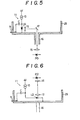
- Figures 4 to 6 show examples of the arrangement of the circuit of Figure 2 in an actual VTR.
- the rotational side circuit 11 is mounted on a rotary drum 29.
- the magnetic head 9 faces outwards.
- the rotary drum 29 is rotated with a shaft 16.
- the optical output of the laser diode LD passes through the lens 12, and it is reflected by a mirror 17 at a right angle. Moreover, it passes through the lens 15 of the stationary side, and reaches the photo-diode PD.
- the mirror 17, the lens 15 and the photo-diode PD are aligned on the central axis of the shaft 16.
- the shaft 16 is hollow and light passes through the interior of the shaft 16.
- light passes from the laser diode LD, through the lenses 12 and 15 and to the photo- diode PD, which are all aligned on the central axis of the shaft 16.
- light may be transmitted through an optical guide material such as a glass fibre between the lenses 12 and 15, and the mirror 17.
- the power source may be connected through a slip-ring or the like.
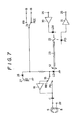
- Figure 7 shows the second embodiment in which signals are recorded (REC) and reproduced (PB). Parts in Figure 7 which correspond to those in Figure 2 are denoted by the same reference numerals.
- a laser diode LD of the rotational side functions as a laser emitting element in the reproducing or playback mode, and it functions as a laser receiving element in the recording mode.
- a recording/reproducing change-over relay switch 18, an amplifier 19, a relay coil 27 for the relay switch 18 and a diode 28, are arranged at the rotational side.
- a recording amplifier 20, a laser diode LD2, a reproducing amplifier 21, a photo-diode PD and a half-mirror 22 are arranged at the stationary side.
- the rotational side and the stationary side are connected to each other through an optical guide material 23 such as an optical fibre. Power sources +B and -B for playback and recording are selectively connected through a switch 24 ⁇ o the rotational side.
- the switches 18 and 24 engage the recording contacts REC, and recording signals are supplied to the amplifier 20.
- the amplified recording signals from the amplifier 20 are converted into an optical output by a laser diode LD2, and the optical output it transmitted through the half-mirror 24, the optical guide material 23 and the lens 12 to the laser diode LD1 to be converted into electrical signals by the laser diode LD1.
- the electrical signals from the laser diode LD1 are transmitted through the switch 18 and the amplifier 19 to the magnetic head 9, and they are recorded on the magnetic tape by the magnetic head 9.
- the switches 18 and 24 engage the playback contact PB.
- the reproduced signals from the magnetic head 9 are supplied through the switch 18 to the laser diode LD1, and they are converted into an optical output by the laser diode LD1.
- the optical output is transmitted through the optical guide material 23 and the half-mirror 22 to the photodiode PD to be converted into electrical signals by the photodiode PD.
- the electrical signals are amplified by the amplifier 21.
- the amplified electrical signals are derived from an output terminal 26.
- the laser diode LD1 is also used as a photoelectric conversion element.
- a photo-diode may be separately provided in the embodiment of Figure 7.
- the output of the photo-diode is supplied through the amplifier 19 to the magnetic head 9.
- the laser element is connected in parallel with the winding of the magnetic head mounted on the rotary member (rotary drum), and a constant current is supplied thereto.
- the photoelectric conversion element is arranged on the stationary part, and a light transmitting means (such as an optical guide material, a lens or a mirror) couples the laser element and the photoelectric conversion element.
- the reproduced signals from the magnetic head are derived from the photoelectric conversion element.
- an optical rotary transformer of the laser diode direct drive type there is provided an optical rotary transformer of the laser diode direct drive type. All of the problems (1) to (3) of the conventional rotary transformer can be overcome. Signals can be reproduced and recorded with high efficiency and good signal-to-noise ratio, and without cross-talk.
Landscapes
- Recording Or Reproducing By Magnetic Means (AREA)
- Optical Communication System (AREA)
Claims (7)
Applications Claiming Priority (2)
| Application Number | Priority Date | Filing Date | Title |
|---|---|---|---|
| JP56144162A JPS5845604A (ja) | 1981-09-11 | 1981-09-11 | Vtr |
| JP144162/81 | 1981-09-11 |
Publications (3)
| Publication Number | Publication Date |
|---|---|
| EP0074796A2 EP0074796A2 (fr) | 1983-03-23 |
| EP0074796A3 EP0074796A3 (en) | 1984-01-18 |
| EP0074796B1 true EP0074796B1 (fr) | 1986-06-18 |
Family
ID=15355635
Family Applications (1)
| Application Number | Title | Priority Date | Filing Date |
|---|---|---|---|
| EP82304724A Expired EP0074796B1 (fr) | 1981-09-11 | 1982-09-08 | Enregistreurs sur bande vidéo |
Country Status (6)
| Country | Link |
|---|---|
| US (1) | US4511934A (fr) |
| EP (1) | EP0074796B1 (fr) |
| JP (1) | JPS5845604A (fr) |
| AU (1) | AU555216B2 (fr) |
| CA (1) | CA1200898A (fr) |
| DE (1) | DE3271776D1 (fr) |
Families Citing this family (15)
| Publication number | Priority date | Publication date | Assignee | Title |
|---|---|---|---|---|
| US4851935A (en) * | 1986-05-14 | 1989-07-25 | Mitsumi Electric Co., Ltd. | Drum assembly for a magnetic recording and reproducing apparatus |
| US4819096A (en) * | 1986-10-23 | 1989-04-04 | Datatape Incorporated | Rotary head scanner including anamorphic beam-shaping apparatus in an optical signal-transmission channel |
| DE3713429A1 (de) * | 1987-04-22 | 1988-11-03 | Thomson Brandt Gmbh | Recorder mit einer rotierenden kopftrommel |
| DE3805436A1 (de) * | 1988-02-22 | 1989-08-31 | Bosch Gmbh Robert | Verfahren zur wiedergabe von datensignalen |
| US4967290A (en) * | 1988-08-26 | 1990-10-30 | Datatape Incorporated | Multiple channel rotary magnetic head scanner having stackable electro-optical signal transmission modules |
| DE3831143A1 (de) * | 1988-09-13 | 1990-03-15 | Broadcast Television Syst | Einrichtung zur uebertragung von signalen zwischen einem feststehenden und einem rotierenden teil |
| US4854662A (en) * | 1988-09-27 | 1989-08-08 | Eastman Kodak Company | Optical data signal apparatus for optically coupling a plurality of data channels between stationary and rotating systems |
| US4875756A (en) * | 1988-09-27 | 1989-10-24 | Eastman Kodak Co. | Fresnel lens apparatus for optically coupling a plurality of data channels |
| US4963995A (en) * | 1988-12-27 | 1990-10-16 | Explore Technology, Inc. | Audio/video transceiver apparatus including compression means |
| US5164839A (en) * | 1988-12-27 | 1992-11-17 | Explore Technology, Inc. | Method for handling audio/video source information |
| US5373404A (en) * | 1989-05-22 | 1994-12-13 | Kabushki Kaisha Sankyo Seiki Seisakusho | Helical scan type rotary head drum unit |
| US5249087A (en) * | 1991-08-16 | 1993-09-28 | Go-Video, Inc. | Rotating head amplifier for vcr |
| KR0121692Y1 (ko) * | 1992-10-31 | 1998-08-01 | 윤종용 | 비데오의 헤드 스위칭 회로 |
| KR0137165Y1 (ko) * | 1995-09-30 | 1999-04-15 | 배순훈 | 회전체의 신호전달 장치 |
| NL1004587C2 (nl) * | 1996-11-21 | 1999-10-01 | Sony Corp | Inrichting met roterende magnetische kop. |
Family Cites Families (6)
| Publication number | Priority date | Publication date | Assignee | Title |
|---|---|---|---|---|
| US2935573A (en) * | 1954-01-11 | 1960-05-03 | Philips Corp | Recorder having visual indicator for high-frequency generator operation |
| GB1312818A (en) * | 1969-07-31 | 1973-04-11 | Licentia Gmbh | Data storage system |
| US3588218A (en) * | 1969-10-27 | 1971-06-28 | Ampex | Multiple spot,optical scanner utilizing periodic light beam refocusing |
| DE2027707A1 (de) * | 1970-06-05 | 1971-12-16 | Ruppel K | Einrichtung zur Aufzeichnung von Ton informationen auf lichtempfindlichen Filmen |
| US4190775A (en) * | 1975-02-18 | 1980-02-26 | Agency Of Industrial Science & Technology | Optical memory playback apparatus |
| JPS5687239A (en) * | 1979-12-18 | 1981-07-15 | Matsushita Electric Ind Co Ltd | Optical recording and reproducing device |
-
1981
- 1981-09-11 JP JP56144162A patent/JPS5845604A/ja active Pending
-
1982
- 1982-09-03 AU AU88006/82A patent/AU555216B2/en not_active Ceased
- 1982-09-08 CA CA000410934A patent/CA1200898A/fr not_active Expired
- 1982-09-08 DE DE8282304724T patent/DE3271776D1/de not_active Expired
- 1982-09-08 EP EP82304724A patent/EP0074796B1/fr not_active Expired
- 1982-09-09 US US06/416,328 patent/US4511934A/en not_active Expired - Fee Related
Also Published As
| Publication number | Publication date |
|---|---|
| AU8800682A (en) | 1983-03-17 |
| CA1200898A (fr) | 1986-02-18 |
| JPS5845604A (ja) | 1983-03-16 |
| AU555216B2 (en) | 1986-09-18 |
| DE3271776D1 (en) | 1986-07-24 |
| EP0074796A3 (en) | 1984-01-18 |
| US4511934A (en) | 1985-04-16 |
| EP0074796A2 (fr) | 1983-03-23 |
Similar Documents
| Publication | Publication Date | Title |
|---|---|---|
| EP0074796A2 (fr) | Enregistreurs sur bande vidéo | |
| KR100203539B1 (ko) | 자기기록재생장치 | |
| JPS5850838A (ja) | 信号伝送装置 | |
| US5363365A (en) | Optical pickup apparatus including a moveable pickup driver using a multiplexer for reducing the number of signal lines | |
| KR0137165Y1 (ko) | 회전체의 신호전달 장치 | |
| US4819096A (en) | Rotary head scanner including anamorphic beam-shaping apparatus in an optical signal-transmission channel | |
| US5933289A (en) | Magnetic recording/reproducing device with wireless transmission of position control signal to head transducer on rotary drum | |
| US4967290A (en) | Multiple channel rotary magnetic head scanner having stackable electro-optical signal transmission modules | |
| JPS5850839A (ja) | 信号伝送装置 | |
| JPH02158901A (ja) | 信号伝送装置 | |
| KR0178215B1 (ko) | 회전체의 신호전달 장치 | |
| JPS5857603A (ja) | 回転型磁気ヘツド装置 | |
| JPS5850840A (ja) | 信号伝送装置 | |
| US20090161525A1 (en) | Optical Pickup and Optical Disk Driving Apparatus Using the Same | |
| JPS62210743A (ja) | 回転体情報伝達装置 | |
| US20050007897A1 (en) | Optical disk device | |
| KR19990012369A (ko) | 테이프 레코더의 헤드 드럼 조립체 | |
| JPH07230602A (ja) | 回転シリンダ給電装置 | |
| JPS63164036A (ja) | 光学ヘツド | |
| JPS586204B2 (ja) | 回転形磁気ヘッド装置 | |
| JP2514186B2 (ja) | 光回転結合器 | |
| JPH10270748A (ja) | 光学装置 | |
| JPH01213801A (ja) | Vtrの回転ヘッド装置 | |
| JP2683276B2 (ja) | 光メモリ読出装置 | |
| JPS62237770A (ja) | 回転体信号伝達装置 |
Legal Events
| Date | Code | Title | Description |
|---|---|---|---|
| PUAI | Public reference made under article 153(3) epc to a published international application that has entered the european phase |
Free format text: ORIGINAL CODE: 0009012 |
|
| AK | Designated contracting states |
Designated state(s): DE FR GB NL |
|
| PUAL | Search report despatched |
Free format text: ORIGINAL CODE: 0009013 |
|
| AK | Designated contracting states |
Designated state(s): DE FR GB NL |
|
| 17P | Request for examination filed |
Effective date: 19840601 |
|
| GRAA | (expected) grant |
Free format text: ORIGINAL CODE: 0009210 |
|
| AK | Designated contracting states |
Kind code of ref document: B1 Designated state(s): DE FR GB NL |
|
| REF | Corresponds to: |
Ref document number: 3271776 Country of ref document: DE Date of ref document: 19860724 |
|
| ET | Fr: translation filed | ||
| PLBE | No opposition filed within time limit |
Free format text: ORIGINAL CODE: 0009261 |
|
| STAA | Information on the status of an ep patent application or granted ep patent |
Free format text: STATUS: NO OPPOSITION FILED WITHIN TIME LIMIT |
|
| 26N | No opposition filed | ||
| PGFP | Annual fee paid to national office [announced via postgrant information from national office to epo] |
Ref country code: GB Payment date: 19950829 Year of fee payment: 14 |
|
| PGFP | Annual fee paid to national office [announced via postgrant information from national office to epo] |
Ref country code: FR Payment date: 19950911 Year of fee payment: 14 |
|
| PGFP | Annual fee paid to national office [announced via postgrant information from national office to epo] |
Ref country code: DE Payment date: 19950918 Year of fee payment: 14 |
|
| PGFP | Annual fee paid to national office [announced via postgrant information from national office to epo] |
Ref country code: NL Payment date: 19950922 Year of fee payment: 14 |
|
| PG25 | Lapsed in a contracting state [announced via postgrant information from national office to epo] |
Ref country code: GB Effective date: 19960908 |
|
| PG25 | Lapsed in a contracting state [announced via postgrant information from national office to epo] |
Ref country code: FR Effective date: 19960930 |
|
| PG25 | Lapsed in a contracting state [announced via postgrant information from national office to epo] |
Ref country code: NL Effective date: 19970401 |
|
| GBPC | Gb: european patent ceased through non-payment of renewal fee |
Effective date: 19960908 |
|
| NLV4 | Nl: lapsed or anulled due to non-payment of the annual fee |
Effective date: 19970401 |
|
| PG25 | Lapsed in a contracting state [announced via postgrant information from national office to epo] |
Ref country code: DE Effective date: 19970603 |
|
| REG | Reference to a national code |
Ref country code: FR Ref legal event code: ST |
|
| REG | Reference to a national code |
Ref country code: FR Ref legal event code: ST |