EP0074901A1 - Bandabwickelvorrichtung und Bandlesegerät mit solcher Vorrichtung - Google Patents
Bandabwickelvorrichtung und Bandlesegerät mit solcher Vorrichtung Download PDFInfo
- Publication number
- EP0074901A1 EP0074901A1 EP82401651A EP82401651A EP0074901A1 EP 0074901 A1 EP0074901 A1 EP 0074901A1 EP 82401651 A EP82401651 A EP 82401651A EP 82401651 A EP82401651 A EP 82401651A EP 0074901 A1 EP0074901 A1 EP 0074901A1
- Authority
- EP
- European Patent Office
- Prior art keywords
- strip
- tape
- strap
- reel
- leader
- Prior art date
- Legal status (The legal status is an assumption and is not a legal conclusion. Google has not performed a legal analysis and makes no representation as to the accuracy of the status listed.)
- Granted
Links
- 230000008878 coupling Effects 0.000 claims abstract description 32
- 238000010168 coupling process Methods 0.000 claims abstract description 32
- 238000005859 coupling reaction Methods 0.000 claims abstract description 32
- 238000004804 winding Methods 0.000 claims abstract description 4
- 230000013011 mating Effects 0.000 claims 1
- 238000003780 insertion Methods 0.000 description 9
- 230000037431 insertion Effects 0.000 description 9
- 230000007246 mechanism Effects 0.000 description 3
- 238000000034 method Methods 0.000 description 3
- 230000006866 deterioration Effects 0.000 description 2
- 238000010586 diagram Methods 0.000 description 2
- 238000006073 displacement reaction Methods 0.000 description 2
- 239000000463 material Substances 0.000 description 2
- 125000006850 spacer group Chemical group 0.000 description 2
- KWGRBVOPPLSCSI-WPRPVWTQSA-N (-)-ephedrine Chemical compound CN[C@@H](C)[C@H](O)C1=CC=CC=C1 KWGRBVOPPLSCSI-WPRPVWTQSA-N 0.000 description 1
- PLXMOAALOJOTIY-FPTXNFDTSA-N Aesculin Natural products OC[C@@H]1[C@@H](O)[C@H](O)[C@@H](O)[C@H](O)[C@H]1Oc2cc3C=CC(=O)Oc3cc2O PLXMOAALOJOTIY-FPTXNFDTSA-N 0.000 description 1
- 238000004026 adhesive bonding Methods 0.000 description 1
- DMFGNRRURHSENX-UHFFFAOYSA-N beryllium copper Chemical compound [Be].[Cu] DMFGNRRURHSENX-UHFFFAOYSA-N 0.000 description 1
- 230000005540 biological transmission Effects 0.000 description 1
- 230000000903 blocking effect Effects 0.000 description 1
- 230000036461 convulsion Effects 0.000 description 1
- 238000000605 extraction Methods 0.000 description 1
- 238000010438 heat treatment Methods 0.000 description 1
- 238000004519 manufacturing process Methods 0.000 description 1
- 229910052751 metal Inorganic materials 0.000 description 1
- 239000002184 metal Substances 0.000 description 1
- 230000003287 optical effect Effects 0.000 description 1
- 239000002985 plastic film Substances 0.000 description 1
- 229920006255 plastic film Polymers 0.000 description 1
- 238000003825 pressing Methods 0.000 description 1
- 238000001454 recorded image Methods 0.000 description 1
- 238000000926 separation method Methods 0.000 description 1
- 230000035939 shock Effects 0.000 description 1
- 230000001360 synchronised effect Effects 0.000 description 1
Images




Classifications
-
- G—PHYSICS
- G11—INFORMATION STORAGE
- G11B—INFORMATION STORAGE BASED ON RELATIVE MOVEMENT BETWEEN RECORD CARRIER AND TRANSDUCER
- G11B15/00—Driving, starting or stopping record carriers of filamentary or web form; Driving both such record carriers and heads; Guiding such record carriers or containers therefor; Control thereof; Control of operating function
- G11B15/60—Guiding record carrier
- G11B15/66—Threading; Loading; Automatic self-loading
- G11B15/67—Threading; Loading; Automatic self-loading by extracting end of record carrier from container or spool
-
- G—PHYSICS
- G03—PHOTOGRAPHY; CINEMATOGRAPHY; ANALOGOUS TECHNIQUES USING WAVES OTHER THAN OPTICAL WAVES; ELECTROGRAPHY; HOLOGRAPHY
- G03B—APPARATUS OR ARRANGEMENTS FOR TAKING PHOTOGRAPHS OR FOR PROJECTING OR VIEWING THEM; APPARATUS OR ARRANGEMENTS EMPLOYING ANALOGOUS TECHNIQUES USING WAVES OTHER THAN OPTICAL WAVES; ACCESSORIES THEREFOR
- G03B21/00—Projectors or projection-type viewers; Accessories therefor
- G03B21/14—Details
- G03B21/32—Details specially adapted for motion-picture projection
- G03B21/321—Holders for films, e.g. reels, cassettes, spindles
Definitions
- the invention relates to a tape drive and its application to a tape drive.
- a tape unwinder is a device for transferring a tape wound in a magazine reel to a take-up reel and vice versa. More generally, the tape constitutes an information medium on which data of analog or digital nature can be recorded, read and possibly erased. Such information carrier tapes are known, for example: photographic films, magnetic tapes, perforable tapes, etc. According to the application which is made of the tape unwinder, the movement of the tape must be continuous, intermittent or jerky as in the cinematographic technique, moreover, in certain applications, the tape unwinder must operate in the two directions of travel, or at least have the capacity to rewind the tape in the reel magazine.
- the operator After placing the magazine reel, also called reel reel, and after opening a side door, inserts the film leader between the rollers and guide rollers. It then hooks this primer on the mandrel of the take-up reel. This operation is long and complex.
- the operator inserts the film primer into a slot, the film perforations mesh on a toothed wheel which drives the primer along a determined circuit.
- This primer hangs on the take-up reel by wedging the lateral flanges then by rubbing the successive turns between them. In practice, this very often results in a risk of deterioration of the primer of the film and sometimes of the film itself as a result of untimely slipping and the poor engagement of the primer during its manual insertion.
- this type of device requires relatively rigid films.
- a tape reader is a device which makes it possible to read, or even analyze the information data recorded on a medium wound on a reel.
- tape drive There are different types of tape drive and, in particular, photographic film tape drives on which the data is recorded in the form of contiguous images which are analyzed according to a television scan to be viewed on the face of a tube. cathode rays.
- the most common analysis technique is that known as the "flying spot" in which an extremely fine light brush sweeps the surface of the film; the light passing through the film is captured by a photoelectric cell, in the case of monochrome images, or after separation of the fundamental components of the light by a plurality of photoelectric cells in the case of polychrome images.
- the strip advances regularly with a perfectly defined frame rate, which significantly simplifies the device on the electronic level, compared to cameras, but reports the difficulty on the mechanical level. It is, in fact, necessary to unroll the strip in a precise manner and to modify the displacement of the light beam in order to compensate for the proper movement of the film. The required precision is difficult to obtain taking into account the mechanical manufacturing tolerances of the film, possible deterioration of the lateral drive perforations, bonding and shrinkage phenomena introduced by variations in temperature and the hygrometric degree of the air.
- the tape is an information medium, generally a photographic film, on which are recorded images arranged in a predetermined order; these images correspond to maps of the regions likely to be overflown.
- the unwinding of the film is synchronous with the speed component of the plane, according to one of the two coordinates of the map and the light brush of the film reading device analyzes only part of the image and is moved transversely in synchronism. with the speed of the airplane according to the other coordinate of the map, and, appropriate means make it possible to present, in the reading corridor of the apparatus, the part of the film corresponding to the geographical position of the airplane.
- This tape reader is associated with a cartographic indicator with cathode ray tube.
- the film tape is large format and a large amount of information data is recorded; the position of the images in the reading lane must be known with great precision; the unwinding of the tape must be able to operate in both directions; the film strip must be able to be changed at will, and the insertion of the film primer must be carried out automatically.
- tape unwinders are in particular information carrier tape recorders used in line scanning optical sensors, lateral beam radar equipment, sonar equipment, etc.
- a device makes it possible to unwind an information support strip and comprises, a reel reel on which the strip is placed and a take-up reel equipped with a drive strap of this band; the leader of the strip and the free end of the strap are provided with mutual coupling means of a plug-in type; these coupling means are placed opposite one another in a plug-in mechanism comprising a decoupling means.
- Such a tape unwinder finds its application in a device making it possible to read the information data recorded on a tape;
- this apparatus comprises a tape loader comprising a box provided with a means for positioning the leader of the tape; the leader of the strip is automatically coupled to a drive strap integral with the take-up reel; the apparatus further comprises means for lateral guidance of the strip in the reading lane and means for measuring the longitudinal position of the strip in this reading lane.
- the primer 4 of the film strip and the free end of the drive strap 6 are provided with coupling means making it possible to join them together, when these two elements are placed opposite one another.
- the device further comprises a coupling mechanism 14 which will be described in detail later.
- the reel 2 and the take-up reel 5 are coupled to rotation means not shown in this figure.
- the strip 3 is a conventional cinematographic film provided with a set of lateral perforations
- one of the guide rollers 12a, 12b may have teeth which engage in the perforations and cause this roller to synchronize with the progress of the bandaged.
- An angular position transducer, not shown, physically coupled to this guide roller can provide a signal representative of the position of the strip in the reading lane.
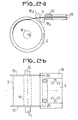
- Figures 2a and 2b show, in a simplified form, respectively in a side view and a transverse view, details of the embodiment of the reel 2 and positioning means of the leader 4 of the strip 3.
- the reel is a conventional coil comprising a pair of flanges 15 integral with a mandrel 16 of axis 01 - 0'1.
- the strip during its unwinding, can be guided by a set of rollers 18a and 18b, mechanically secured to a frame which supports the reel reel and, optionally, the means for rotating this reel on the mandrel 166.
- FIG. 2b shows that the leader 4 of the strip is equipped with a set of buttons 21 which are intended to be inserted in corresponding receptacles provided on the free end of the strap 6 of the take-up reel 5.
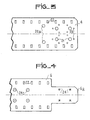
- FIG. 3 shows the arrangement of the means for coupling the primer 4 of the strip 3 with the drive strap 6.
- This strip is, for example, a conventional photographic film, provided with its lateral perforations 22.
- the primer of the film is provided with a set of buttons 21 suitably distributed and this primer comprises circular perforations 20a intended to receive the positioning feet 20 shown in FIGS. 2a and 2b.
- the positioning feet are of rectangular section and arranged opposite the lateral perforations 22.
- the band leader also comprises series of circular perforations 23, each series being regularly arranged around each of the buttons 21; the function of these circular perforations 23 is to allow the free passage of fingers intended to separate the coupling buttons 21 from the corresponding receptacles located on the free end of the drive strap 6.
- FIG. 4 shows the arrangement of the means for coupling the drive strap 6 with the primer 4 of the strip shown in FIG. 3.
- the width of the drive strap 6 is equal to that of the strip and is also provided with lateral perforations 22.
- the end part 6a of the strap is of reduced width so as to fit into the corresponding part of the guide element 19 shown in FIG. 2b.
- This end portion 6a of the drive strap is provided with a set of buttonholes 24 corresponding to the buttons 21 located on the leader of the strip.
- the drive strap 6 can be made of a material identical to that of the strip 3 or of a different material, for example, a flexible metal such as beryllium copper after heat treatment.
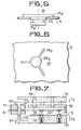
- Figure 5 shows an embodiment of the coupling buttons 21 located on the leader 4 of the strip.
- a button comprises a head 21a of small thickness and a foot 21b, this foot comprising a circular groove 21c intended to engage in a buttonhole 24 located on the free end of the drive strap 6.
- These coupling buttons 21 can be held by gluing on the leader of the strip.
- a button can be formed from two elements crimped onto the leader of the strip.
- Figure 6 shows an embodiment of the buttonholes 24 located on the free end of the drive strap.
- a buttonhole is formed by a circular perforation 24a made in the strap; the diameter of this circular perforation being substantially equal to the inside diameter of the groove 21c of the button 21.
- linear perforations 24b are arranged around the circular perforation 24a, for example three slots as shown.
- these buttonholes could be snaps of the female type.
- the first movable plate 31 has a clearance 33 located opposite the positioning foot 20, this clearance being provided with a pin 34 intended to push this positioning foot towards the top of the figure during the coupling operation of the leader 4 of the strip with the strap 6.
- the first movable plate is provided with a set of sliding buttons 35 mounted resiliently on springs in housings 36 , the function of these buttons being to hold in place the free end of the drive strap when the leader 4 of the strip is uncoupled and therefore secured to the strip loader.
- the second movable plate 32 also includes a clearance 37 located opposite the positioning foot 20, with the aim of - pushing this positioning foot downwards in the figure during the operation of uncoupling the primer 4 with the strap 6.
- This second movable plate is provided with a series of fingers 38 located opposite the perforations 23, with the aim of pressing on the primer and of uncoupling the buttonholes 24 of the buttons 21.
- the leader 4 of the strip being correctly positioned inside the plate 30, by means of the positioning foot 20 and the receptacles 24 of the strap 6 being hooked in the buttons 35, the movement of the first movable plate 31 towards the fixed plate 30 allows the strap 6 to be hooked onto the buttons 21 and frees the positioning feet 20.
- the movement of the second movable plate by the play of the fingers 38, uncouples the buttons 21, transfers the strap onto the buttons 35 and reengages the positioning feet 20 in the leader 4 of the strip.
- the displacements of the plates 31 and 32 can be carried out manually or mechanically, using electromagnets for example.
- a tape drive comprising a tape drive according to the invention; this tape unwinder comprising means for unwinding and positioning the tape and an optronic assembly making it possible to analyze the part of the tape crossing the reading corridor.
- This tape drive is more specifically designed for application to a navigation from geographic data recorded on a film strip.
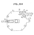
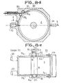
- FIG 8a shows, in a side view, an embodiment of a film loader 50; this film loader comprises a box 51 inside which is disposed a reel on which is wound the film strip 3 to be analyzed.
- the case 51 is provided with means 52 for plugging into the tape drive.
- the positioning of the loader 50 in the tape unwinder is carried out by the guide 52 and the centralizers with stops 53; a retractable handle 54 allows its insertion or extraction.
- the primer 4 of the film strip is guided and positioned by the lateral guides 19.
- the housing further comprises positioning feet 20 of the film primer, a stopper 55 of the positioning feet and, finally, guide rollers 18a and 18b of the film.
- FIG. 8b represents a transverse view of the magazine 50 showing the location of the positioning feet 20 of the film primer and of the confinement stop 55; in addition, it can be seen that the guide element 19 of the film comprises two lateral guides 19a and 19b in which the film strip which is not shown scrolls, moreover, in this figure, it can be seen that the guides 52a and 52b of the magazine are crossed by a transmission shaft 56 provided with a toothed pinion 57.
- Figure 8c shows the details of the positioning feet 20 of the film leader located in the positioning element 19 shown in Figure 8b.
- These movable positioning feet can occupy two stable positions: a first position, as shown , corresponding to the blocking of the film primer 4 and a second portion corresponding to a position for releasing the film primer.
- these positioning feet include two circular grooves 20a and 20b in which elastic ball bearings 20c can engage; each of the positioning feet 20 opens into a clearance 19c, intended to receive the movable pins 34 (FIG. 7) making it possible to lift these feet in order to release the primer from the film 4.
- Figure 8d shows a side sectional view of the film feeder 50, showing the position of the reel 2 inside the housing 51 and the relative position of the two guide rollers, 18a and 18b respectively.
- FIG. 8e represents a cross-sectional view of the film feeder 50.
- the housing 51 of the film feeder of substantially parallelepiped or cylindrical shape has two lateral faces 5la and 51b of which at least one of them is removable to allow loading of the reel 2.
- This reel comprises a pair of flanges 2a and 2b secured to a mandrel 16 which is guided in rotation by two ball bearings 56a and 56b respectively and has, at one of its ends, a pinion keyed 57 intended to be coupled to a means for rotating this reel.
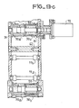
- Figures 9a and 9b show, respectively, in a side section and a rear transverse view, an embodiment of the tape drive equipped with its film loader.
- the tape drive comprises a frame consisting, for information only, of two distant flanges 60a and 60b, secured by a set of spacers, such as spacers 61 to 67. This frame is positioned relative to the light element 100 providing a light brush for analyzing the image recorded on the film, the light beam passing through the film is analyzed by an element 200, these two elements being known per se and not forming part of the invention will not be described.
- the frame supports, in addition, a first drive member 70 secured to the reel, a second drive member 71 secured to the take-up reel 5 and an angular position transducer 72 which provides a signal for measuring the position of the strip in the film press analysis window 9b.
- the film press element 8b has two grooves 73 and 74 allowing the free passage of the buttons 21 of the film leader and of the free end of the drive strap 6.
- the mandrel 7 of the take-up reel comprises two grooves 7a and 7b intended for housing these delivery means fully 21; in addition, the drive strap 6 has, for this purpose, perforations 24c (Fig.4) judiciously spaced allowing the buttons 21 to freely cross this strap during winding in order to be housed in these grooves 7a and 7b.
- the distance from the perforations 24c to the buttonholes 24 corresponds to one winding turn.
- the number of arrangement of holes 24a is determined to absorb the radial thickness present by the buttons 21.
- the rollers such as 13a and 13b can be constituted by a fixed cylindrical part, equipped with a set of ball bearings 69a and 69b .
- the mandrel 7 of the take-up reel 2 comprises a means for fixing the drive strap constituted, for example, by a plate 7e fixed by screws 7c and this mandrel is made integral with its rotation shaft 79 by screws 7d.
- the frame further comprises a stop 80 which engages in the guide element 53 of the tape feeder 50, a detector 81 making it possible to detect the insertion of this feeder and a slide 82 intended to receive the guides 52 of the charger.
- Figure 9c shows, in a sectional view, an embodiment of the guide rollers 12a and 12b.
- the longitudinal and transverse positions of the film must be determined with precision. The tolerance on the width of the film does not allow the film to be positioned laterally between two fixed guides.
- the guide elements are carried on the rollers 12a and 12b, each of these rollers comprises two cylindrical elements 90a and 90b nested concentrically, in an elastic manner, each of these two elements is provided with cheeks 91.
- one of the guide rollers is provided with teeth 92, the transverse thickness of which is substantially less than the width of the lateral perforations of the film and the radial thickness of which is equal to the length lateral perforations of the film.
- the angular position transducer 72 is mechanically coupled to the shaft and provides an electrical signal representative of the position of the part of the strip engaged in the reading lane of the device. In order to know unambiguously the position of the film, the successive cycles of the output signal from the transducer 72 can be counted.
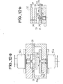
- FIG. 10a represents, in a cross-section view, an embodiment of the mechanical coupling member 14 making it possible to insert the buttons located on the leader of the strip in the corresponding buttonholes arranged on the free end of the belt drive strap.
- This mechanical member 14 comprises the fixed plate 30 secured to the frame of the reading device; this fixed element comprises an internal housing 30a, U-shaped, intended to ensure the free passage of the positioning means 19 of the leader 4 of the strip. Inside this housing 30a, is disposed the first movable plate 31 provided with retractable buttons 35 which provide the means for hooking the free end of the strap for driving the strip.
- the second mobile plate 32 is disposed outside of the fixed element 30 and, opposite the first mobile plate, this second mobile plate is provided with a set of fingers 38, intended to separate the leader from the strip and the free end of the drive strap of this strip.
- the movements of the movable plates are provided respectively by drive members 82a and 82b which can be, for example, conventional electromagnets controlled by pushbuttons not shown.
- Figure 10b shows, in a partial side view, the mechanical coupling member 14 of Figure 10a.
- the first movable plate 31 has the clearance 33 on which the pins 34 are arranged intended to push back the positioning feet 20 of the leader 4 of the strip.
- the second movable plate 32 includes the symmetrical recess 37 of the recess 33, intended to engage the positioning feet 20 of the leader 4 of the strip.
- the width of the strip can be relatively large, this strip can be relatively thin and flexible since the operation of inserting the leader of the strip through the guide rollers and the reading passage is eliminated.
- the tape loader is of the single-coil type, therefore of reduced dimensions and its loading in 1 reading device is extremely simple and convenient to carry out; the coupling of the tape leader to the take-up reel can be completely automatic.
- the unwinding device can be produced in a compact and particularly robust form allowing its implementation in devices intended for vehicles subjected to shocks and vibrations of high level.
- the position of the strip in the reading lane can be known precisely.
- the invention is not limited to the embodiments which have just been described, in particular the relative positions and the shape of the various elements can be adapted to the applications envisaged for the nature of the strip to be analyzed.
- the read-write heads can be retractable and partially erased to allow free passage of the means of coupling of the drive strap to the start of the tape.
- the indexing of the band may be different and in particular be carried out by electronic or optronic means.
- a tape drive according to the invention finds its application in devices for reading and / or recording on tape analog or digital data.
- the strip to be unrolled can be of various types: plastic film, paper tape or metallic or metallized tape.
Landscapes
- Physics & Mathematics (AREA)
- General Physics & Mathematics (AREA)
- Replacement Of Web Rolls (AREA)
- Storing, Repeated Paying-Out, And Re-Storing Of Elongated Articles (AREA)
- Organic Insulating Materials (AREA)
- Magnetic Record Carriers (AREA)
Applications Claiming Priority (2)
| Application Number | Priority Date | Filing Date | Title |
|---|---|---|---|
| FR8117234A FR2512996B1 (fr) | 1981-09-11 | 1981-09-11 | Derouleur de bande et lecteur de bande comprenant un tel derouleur |
| FR8117234 | 1981-09-11 |
Publications (2)
| Publication Number | Publication Date |
|---|---|
| EP0074901A1 true EP0074901A1 (de) | 1983-03-23 |
| EP0074901B1 EP0074901B1 (de) | 1985-11-21 |
Family
ID=9262075
Family Applications (1)
| Application Number | Title | Priority Date | Filing Date |
|---|---|---|---|
| EP82401651A Expired EP0074901B1 (de) | 1981-09-11 | 1982-09-10 | Bandabwickelvorrichtung und Bandlesegerät mit solcher Vorrichtung |
Country Status (5)
| Country | Link |
|---|---|
| US (1) | US4467983A (de) |
| EP (1) | EP0074901B1 (de) |
| JP (1) | JPS5857123A (de) |
| DE (1) | DE3267613D1 (de) |
| FR (1) | FR2512996B1 (de) |
Families Citing this family (5)
| Publication number | Priority date | Publication date | Assignee | Title |
|---|---|---|---|---|
| JPH0610738Y2 (ja) * | 1987-06-30 | 1994-03-23 | 小橋工業株式会社 | 耕深調節装置 |
| US6037973A (en) * | 1997-04-02 | 2000-03-14 | Cinema Products Corporation | Film transport and method |
| US6644580B2 (en) | 2000-11-29 | 2003-11-11 | Fujitsu Limited | Take up assembly for wrapping spaced tape portions |
| US6540167B2 (en) | 2000-11-29 | 2003-04-01 | Fujitsu Limited | Take up assembly door mechanism |
| US8130464B2 (en) * | 2007-11-21 | 2012-03-06 | Oracle America, Inc. | Method and system for compensating for tape deformation |
Citations (2)
| Publication number | Priority date | Publication date | Assignee | Title |
|---|---|---|---|---|
| FR1044194A (fr) * | 1951-10-26 | 1953-11-16 | Perfectionnements aux dispositifs de fixation du film sur les bobines d'appareils photographiques et cinématographiques | |
| US3025011A (en) * | 1959-03-23 | 1962-03-13 | Armour Res Found | Single spool magazine tape recorder |
Family Cites Families (1)
| Publication number | Priority date | Publication date | Assignee | Title |
|---|---|---|---|---|
| US3880382A (en) * | 1972-10-26 | 1975-04-29 | Int Video Corp | Tape extractor for magnetic tape cartridge system |
-
1981
- 1981-09-11 FR FR8117234A patent/FR2512996B1/fr not_active Expired
-
1982
- 1982-08-31 US US06/413,510 patent/US4467983A/en not_active Expired - Fee Related
- 1982-09-09 JP JP57157380A patent/JPS5857123A/ja active Pending
- 1982-09-10 EP EP82401651A patent/EP0074901B1/de not_active Expired
- 1982-09-10 DE DE8282401651T patent/DE3267613D1/de not_active Expired
Patent Citations (2)
| Publication number | Priority date | Publication date | Assignee | Title |
|---|---|---|---|---|
| FR1044194A (fr) * | 1951-10-26 | 1953-11-16 | Perfectionnements aux dispositifs de fixation du film sur les bobines d'appareils photographiques et cinématographiques | |
| US3025011A (en) * | 1959-03-23 | 1962-03-13 | Armour Res Found | Single spool magazine tape recorder |
Also Published As
| Publication number | Publication date |
|---|---|
| FR2512996A1 (fr) | 1983-03-18 |
| JPS5857123A (ja) | 1983-04-05 |
| DE3267613D1 (en) | 1986-01-02 |
| US4467983A (en) | 1984-08-28 |
| FR2512996B1 (fr) | 1985-11-08 |
| EP0074901B1 (de) | 1985-11-21 |
Similar Documents
| Publication | Publication Date | Title |
|---|---|---|
| FR2724043A1 (fr) | Systeme destine a referencer un ensemble de prelevement a un emplacement de stockage | |
| CH659902A5 (fr) | Lecteur mixte pour cartes a piste magnetique et/ou a puce electronique. | |
| EP1505334A1 (de) | Stabilisiertes Plattform-system | |
| EP0181789A1 (de) | Hochauflösungsbilderzeugungsanlage zur Entwicklung in Echtzeit von isolierten Filmen | |
| EP0074901B1 (de) | Bandabwickelvorrichtung und Bandlesegerät mit solcher Vorrichtung | |
| US5327306A (en) | Compact magnetic recording and reproducing device having movable reels and reel spindles | |
| CH643966A5 (fr) | Adaptateur pour cassette de bande du type miniature. | |
| EP0180489A1 (de) | Gerät zur Aufnahme und Wiedergabe von Informationen auf Magnetband | |
| FR2683662A1 (fr) | Dispositif de detection de fin de bande, pour platine de bande magnetique. | |
| FR2723873A1 (fr) | Ensemble de structure, de guidage et d'entrainement destine a une translation d'un ensemble robotique de prelevement | |
| US5761557A (en) | Film transport device | |
| US3402982A (en) | Electro-optical system | |
| EP0907903B1 (de) | Kinematographische kamera und aufnahmevorrichtung für filmspulen | |
| EP0768667B1 (de) | Magnetisches Aufzeichnungs- und Wiedergabegerät und Videokamera damit | |
| JPS6131542B2 (de) | ||
| JPS5894173A (ja) | ビデオテ−プカセツト | |
| US20080204927A1 (en) | Magnetic recording/reproducing apparatus | |
| EP0783166B1 (de) | Prüfungs- und Zentrierungsvorrichtung zum Einlegen von Kassetten | |
| EP0050175B1 (de) | Projektionsgerät zum Betrachten von Mikrofilmkassetten | |
| JPH09127619A (ja) | フィルムキャリア | |
| EP0989551A1 (de) | Kassettentransportmechanismus für Plattenspieler | |
| FR2745096A1 (fr) | Procede et appareil pour visualiser et/ou enregistrer des selections photographiques a partir de negatifs ou diapositives | |
| FR2561006A1 (fr) | Dispositif audiovisuel a cassette, cassette et projecteur ou visionneuse pour la mise en oeuvre de ce dispositif | |
| US20050069311A1 (en) | Photographic device | |
| FR2787667A1 (fr) | Visualisation de photographies sur ecran de television a l'aide d'un magnetoscope |
Legal Events
| Date | Code | Title | Description |
|---|---|---|---|
| PUAI | Public reference made under article 153(3) epc to a published international application that has entered the european phase |
Free format text: ORIGINAL CODE: 0009012 |
|
| AK | Designated contracting states |
Designated state(s): DE GB IT SE |
|
| 17P | Request for examination filed |
Effective date: 19830822 |
|
| GRAA | (expected) grant |
Free format text: ORIGINAL CODE: 0009210 |
|
| AK | Designated contracting states |
Designated state(s): DE GB IT SE |
|
| PG25 | Lapsed in a contracting state [announced via postgrant information from national office to epo] |
Ref country code: IT Free format text: LAPSE BECAUSE OF FAILURE TO SUBMIT A TRANSLATION OF THE DESCRIPTION OR TO PAY THE FEE WITHIN THE PRESCRIBED TIME-LIMIT;WARNING: LAPSES OF ITALIAN PATENTS WITH EFFECTIVE DATE BEFORE 2007 MAY HAVE OCCURRED AT ANY TIME BEFORE 2007. THE CORRECT EFFECTIVE DATE MAY BE DIFFERENT FROM THE ONE RECORDED. Effective date: 19851121 |
|
| PG25 | Lapsed in a contracting state [announced via postgrant information from national office to epo] |
Ref country code: SE Effective date: 19851130 |
|
| REF | Corresponds to: |
Ref document number: 3267613 Country of ref document: DE Date of ref document: 19860102 |
|
| PLBE | No opposition filed within time limit |
Free format text: ORIGINAL CODE: 0009261 |
|
| STAA | Information on the status of an ep patent application or granted ep patent |
Free format text: STATUS: NO OPPOSITION FILED WITHIN TIME LIMIT |
|
| 26N | No opposition filed | ||
| PGFP | Annual fee paid to national office [announced via postgrant information from national office to epo] |
Ref country code: GB Payment date: 19920813 Year of fee payment: 11 |
|
| PGFP | Annual fee paid to national office [announced via postgrant information from national office to epo] |
Ref country code: DE Payment date: 19920817 Year of fee payment: 11 |
|
| PG25 | Lapsed in a contracting state [announced via postgrant information from national office to epo] |
Ref country code: GB Effective date: 19930910 |
|
| GBPC | Gb: european patent ceased through non-payment of renewal fee |
Effective date: 19930910 |
|
| PG25 | Lapsed in a contracting state [announced via postgrant information from national office to epo] |
Ref country code: DE Effective date: 19940601 |