EP0075155A2 - Procédé pour le nettoyage de filets de trous borgnes d'un récipient sous pression d'un réacteur, le couvercle du réacteur étant monté ou démonté, par une machine à nettoyer, ainsi que machine pour la mise en oeuvre du procédé - Google Patents
Procédé pour le nettoyage de filets de trous borgnes d'un récipient sous pression d'un réacteur, le couvercle du réacteur étant monté ou démonté, par une machine à nettoyer, ainsi que machine pour la mise en oeuvre du procédé Download PDFInfo
- Publication number
- EP0075155A2 EP0075155A2 EP82108082A EP82108082A EP0075155A2 EP 0075155 A2 EP0075155 A2 EP 0075155A2 EP 82108082 A EP82108082 A EP 82108082A EP 82108082 A EP82108082 A EP 82108082A EP 0075155 A2 EP0075155 A2 EP 0075155A2
- Authority
- EP
- European Patent Office
- Prior art keywords
- thread
- drive
- cleaning
- machine
- tool carrier
- Prior art date
- Legal status (The legal status is an assumption and is not a legal conclusion. Google has not performed a legal analysis and makes no representation as to the accuracy of the status listed.)
- Granted
Links
Images


Classifications
-
- B—PERFORMING OPERATIONS; TRANSPORTING
- B23—MACHINE TOOLS; METAL-WORKING NOT OTHERWISE PROVIDED FOR
- B23G—THREAD CUTTING; WORKING OF SCREWS, BOLT HEADS, OR NUTS, IN CONJUNCTION THEREWITH
- B23G1/00—Thread cutting; Automatic machines specially designed therefor
- B23G1/02—Thread cutting; Automatic machines specially designed therefor on an external or internal cylindrical or conical surface, e.g. on recesses
Definitions
- the invention relates to a method for cleaning blind hole threads in reactor pressure vessels with and removed. overlying reactor cover by a cleaning machine, essentially during the revision phase when using the machine from the work platform to which it is connected as a mobile hanging structure, and a machine suitable for carrying out the process.
- a likewise vertically arranged device for cleaning the threaded holes machined in the upper edge of a pressure vessel and / or the bolts to be screwed into them became known from DT-OS 25 06 214.
- the criterion of this device is that the extractable cleaning brush rotating about its axis is guided in a circular path around the respective thread during the drive, and in addition to the motor for the spindle drive, a second motor for guiding the spindle on the peripheral path around the Thread is required.
- Such a device is not suitable for the generally intended, sequential cleaning of the individual blind hole threads in the reactor pressure vessel (hereinafter referred to as RDB according to today's terminology) with the RDB lid on.
- RDB reactor pressure vessel
- the revisions generally follow from a special work or inspection platform, which is usually located about 12 m above the RPV.
- Devices of this type are suitable for cleaning external threads.
- German patent specification 27 32 882 discloses a device for cleaning internal threads of nuts, in particular those with large dimensions, in which a vertically arranged shaft which ends in a cleaning head equipped with cleaning tools can be axially displaced in a housing.
- the cleaning head is pushed against the thread from below and moves by positive locking with it over the thread section, the cleaning head being extended again by reversing the direction of rotation.
- a frame equipped with a special tilting device is provided for the support.
- the device must be easy to use if the shortest changeover times are observed.
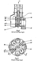
- the step-like machine constructed from five main parts A to E and constructed as a hanging structure, is connected in a manner known per se via mobile means of the working platform which can be adjusted both vertically and in terms of their boom width. These means allow an exact entry into the respective working position, this process being completed by moving the lower drive part D into the corresponding through opening of the RPV cover for this aid.
- the machine is controlled further by actuating the remote control keyboard connected to control head A.
- control block accommodates the main valve for the pneumatic control, with compressed air connections being provided for supplying the machine with control air, with working air for driving the drive motor and for supplying the area to be cleaned with blown air. **
- the directional valve switch Connected to the control block is the directional valve switch arranged in the upper area of the housing for initiating the commands "engine start-right-hand rotation” and “blowing air on”, and in the lower area a second directional valve switch to be set according to the desired stroke distance for initiating the commands "engine -Stop "and” Motor start counter-clockwise rotation ".
- the blowing air is only set when the brush head emerges from the thread and becomes in usually given when the initial position of the brush head or the drive unit carrying it is reached again.
- the initially given forced guidance of the brush head in the axial direction by the lifting cylinder ensures its exact engagement in the thread and in the opposite direction, after completion of its cleaning process, its perfect removal from the thread, so that "regrinding" of the first threads is avoided.
- the blown air inlet via the brush head in conjunction with the effective extraction of the area to be cleaned, protects the operating personnel from any risk of contamination.
- the blown air flows into two ring ducts, starting from a central feed, arranged in radially directed connections in different planes, the duct leading first into the thread, lying at the bottom, conveying the blown air in the direction of the nozzles, which loosen the loosening causing the buildup while the overhead ring channel transfers the air to the radial circular brushes to assist in final cleaning, and that the continuation of the central air supply leads into an outlet which narrows towards the end in the shape of a nozzle, and the air leads to the bottom of the blind hole thread, where, in conjunction with vertically oriented disc brushes, it lifts off the deposits and makes them accessible for suction.
- the supply of the blown air via two different levels into the thread while at the same time supplying a partial air quantity directed against the root of the thread ensures an optimal loosening and cleaning with simultaneous adjustment of flows effective for the exhaust air extraction.
- a proposed combination of radially directed round brushes and plate brushes arranged parallel to the shaft and directed against the bottom of the thread is particularly cleaning-intensive.
- the brush head or the blown air supply in the cleaning area can be freely designed and adapted to the respective requirements.
- the brush head e.g. is interchangeable with a so-called molycotization device.
- This consists of a felt disc package soaked with Molykote, which is cylindrically shaped according to the thread diameter, which enables intensive thread care after cleaning.
- the air to be extracted is captured by suction nozzles attached to the brush head, and by means of a rotating sleeve that surrounds the tool carrier shaft. bound pipe sealingly opens into an exhaust air collection chamber that can only be moved vertically, while the tool carrier shaft, also sealing, leads through this chamber, and that the exhaust air from the exhaust air collection chamber is guided via at least one suction pipe designed as a telescopic cable that opens into the intermediate piece and from there is connected via further connections to the plant network equipped with suitable filters.
- the flexible hose lines can be detached and the actual suction pipes can be pierced from top to bottom using suitable aids, so that the loosened, essentially in the exhaust air accumulating dirt particles, when restoring the connection in the intermediate piece, can also be fed to the plant network by suction.
- a device which enables the method to be carried out provides that a drive unit for driving the tool carrier shaft is formed in the housing of the drive upper part, which, on a drive carrier plate, is directed towards the drive side, a long bearing combination for the radial and axial guidance of the shaft passing through the tool carrier plate and here positively connected to a spur gear, and one Compressed air vane motor, the drive shaft extends through the carrier plate,
- the clear structure of the drive unit for the tool carrier shaft arranged in the housing of the upper drive part and the means for connecting or disconnecting it from the lifting cylinder allow simple control and maintenance via an assembly cover arranged in the housing of the upper drive part.
- the guiding of the drive carrier plate in the housing arranged axially parallel to the tool carrier shaft secures interacting with the other guide means of the tool carrier shaft, their tilt-free axial guidance.
- the drive unit and the tool carrier shaft as well as the parts of the suction connected to it, ie the casing tube, the suction chamber and the suction tubes directly adjoining this, are connected to a counterweight which is displaceably guided in the housing.
- control block A equipped with a main valve.
- compressed air connections A ' are provided for supplying the machine with control air, with working air for driving the drive motor, which is preferably designed as a compressed air vane motor 8, and for supplying the cleaning area with blown air.
- control line A is connected to the suction line A '' 'and the suspension for the machine.
- control block A is designed as a maintenance unit for lubrication, water separation, etc., and is provided with connections for a pneumatic remote control A "of the machine.
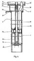
- the control block A is adjoined at the bottom by the cylindrical housing 17 of the upper drive part B, the head 2 of the tool carrier shaft 1 being rotatably guided axially and radially in a long bearing combination 3 designed for the blown air supply 4.
- the tool carrier shaft head 2 passes through the drive carrier plate 5 and is then, i.e. arranged below, positively connected to a spur gear 6, which also in this spur gear 6. below the drive carrier plate 5, which is arranged axially parallel to the tool carrier shaft 1 and which is driven by a compressed air lamella motor 8 installed on the drive carrier plate 5, engages pinion 7.
- the lifting cam 9 is provided axially parallel to the tool carrier shaft 1 for the engagement of a lifting lug 10 on the drive carrier plate 5, which is pivotally connected to the head of the piston rod 12 of the lifting cylinder 11 and initially engages in the lifting cam 9 in a form-fitting manner.
- the drive carrier plate 5 is guided in cylindrical columns 13 arranged axially parallel to the tool carrier shaft 1.
- the essential parts of the drive are accessible via a large mounting opening 17 'which can be closed in the housing 17.
- Commissioning usually takes place after the lower drive part D (ie the guide tube) has been moved into the RPV cover, an intermediate piece C described later being flanged between the lower drive part D and the upper drive part B, which is supported via the flange 37 of the lower drive part D described later .
- the further commissioning is effected by the actuation of the lifting cylinder 11, which in turn causes a roller lever 15 to actuate the directional control valve switch "engine start-clockwise rotation” and “blowing air on” in the course of its stroke.
- the lifting cylinder 11 leads the drive carrier plate 5 down until the brush head E engages in the thread in the RPV, in which position the stroke of the piston rod 12 of the lifting cylinder 11, which is controlled by a linkage 16, pivots the lifting lug 10 out of the lifting cam 9 and thus the further movement of the tool carrier shaft 1 releases.
- the tool carrier shaft 1 is now moved independently of the lifting cylinder 11 by positive locking between the brush head E carried by it with the thread to be cleaned, i.e. the brush head E is screwed into the thread.
- the screw-in path of the brush head E generally corresponds to the thread length, the lowest point being determined by a lower roller lever 15 'for actuating the directional control valve switches "motor stop” and "motor start anticlockwise rotation”.
- the location of the weight 18th is fixed within the housing 17 in the axial direction thereof by guide columns 18 '.
- a rope pulley 19 is connected to the upper end flange 20 of the housing 17 and a rope pulley 19 'to the lower end flange 20' of the housing 17 and to the counterweight 18 via a rope 19 "with the parts to be relieved.
- the counterweight 18 is a the check 'drive parts, exhaust pipes, etc. ausquaintder molding.
- the blown air duct 4 opens into the annular space 3 'formed by the long bearing combination 3.
- the long bearing combination 3 is connected to the drive carrier plate 5.
- the head 2 of the tool carrier shaft 1 is axially and radially guided in this long bearing combination 3.
- the compressed air is guided via a control valve into the annular space 3 ′ given there and enters through radially directed bores 21 into a bore 22 directed centrally through the tool carrier shaft head 2, the head 2 into a bore connected to it Transferred precision steel tube 23, which essentially forms the tool carrier shaft 1.
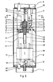
- the tool carrier shaft 1 leads into an end piece 24 delimited by flange 25, the flange 25 also being the carrier of the casing tube 26 for the exhaust air supply described later.
- the tool carrier shaft 1 can be separated in the intermediate piece C by a coupling 27.
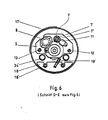
- the actual brush head E is connected to the flange 25 and generally has four radially directed round brushes 28 and two plate brushes 29 axially directed against the thread root in the RPV.
- the air is guided centrally in this area.
- the blown air enters from here radially in two superimposed planes annular channels 30 and 30 ', which are open in the area of the radially directed round brushes 28, and via additional directional nozzles 30' 'into the threads.
- the further axial continuation of this central blown air supply tapers towards the nozzle-shaped end, this end 31 guiding the blown air against the bottom of the blind hole thread of the RPV.
- this brush head E another head can be put on, which consists of felt disks 40 corresponding to the thread. are usually soaked with molykote.
- the suction serves to remove the dirt particles cleaned from the threads and it connects to the control block A and leads further through the cylindrical housing 17 of the upper drive part B, through the intermediate piece C, through the lower drive part D designed as a guide tube and from there into the Tool jacket shaft 1 comprising a suction jacket pipe 26, in order to ultimately open into two suction ports 32 connected to the brush head E and the tool table shaft 1.
- the rotating suction jacket tube 26 opens in the direction of suction in the lower drive part D into a non-rotating exhaust air collection chamber 33 which is adjustable in its axial direction, and which seals against it.
- the actual tool carrier shaft 1 leads in the further passage through this chamber 33 and emerges from it together with the chamber 33 in an axially displaceable manner and is sealed against it.
- Fixed exhaust pipes 34 are connected to the exhaust air collection chamber 33, each of which is designed as a telescopic cable 35 leading upwards.
- the tubes end in the lower limiting flange 36 of the intermediate piece C leading to the upper drive part B.
- the intermediate piece C is based on a flange 37 which is claw-shaped on one side, which acts as a torque support against the RPV cover.
- two suction pipes 34 lead from the exhaust air collection chamber 33 through the lower drive part D into the intermediate piece C.
- the respective opening area of the respective suction pipe 34 is connected via a detachable hose connection 38 to the suction pipe 34 ′′ leading through the upper drive part B, respectively.
- the intermediate piece C the upper part of the tool carrier shaft 1 can also be separated from the lower part thereof by the coupling 27.
- the intermediate piece C is provided with a mounting cover 39, so that from here the tool carrier shaft 1 can be separated and replacement parts can be installed.
- the hose connections 38 of the suction pipes 34/34 ' can be removed, so that from here each suction pipe 34,. e.g. can be cleaned by ejecting with suitable aids.
- the suction pipes 34 ' are connected to the plant network by B and A and the extracted air is cleaned in suitable filters.
- This machine can also be used to clean dismantled nuts on a separate parking ring.
- the flexible suction line on control block A is removed.
- the suction then takes place via an adapter 41 which engages over the nut and to which a modified suction line 42, which also leads to a filter device, is connected at the bottom.
- the workplace is ventilated here via the exposed suction lines.
- a second idler gear 7 ' which engages in the spur gear 6 and is provided with a square neck 7' 'which engages through the drive carrier plate 5 is provided.
- This pinion can be driven via a hand crank to be attached to the work platform. The brush head E can thus be screwed back manually.
Landscapes
- Engineering & Computer Science (AREA)
- Mechanical Engineering (AREA)
- Cleaning In General (AREA)
Applications Claiming Priority (2)
| Application Number | Priority Date | Filing Date | Title |
|---|---|---|---|
| DE19813135882 DE3135882C2 (de) | 1981-09-10 | 1981-09-10 | Vorrichtung zur Abreinigung von Sacklochgewinden in Reaktor-Druckbehältern (RDB) bei abgenommenem oder aufliegendem Reaktordeckel |
| DE3135882 | 1981-09-10 |
Publications (3)
| Publication Number | Publication Date |
|---|---|
| EP0075155A2 true EP0075155A2 (fr) | 1983-03-30 |
| EP0075155A3 EP0075155A3 (en) | 1983-07-27 |
| EP0075155B1 EP0075155B1 (fr) | 1986-04-09 |
Family
ID=6141322
Family Applications (1)
| Application Number | Title | Priority Date | Filing Date |
|---|---|---|---|
| EP19820108082 Expired EP0075155B1 (fr) | 1981-09-10 | 1982-09-02 | Procédé pour le nettoyage de filets de trous borgnes d'un récipient sous pression d'un réacteur, le couvercle du réacteur étant monté ou démonté, par une machine à nettoyer, ainsi que machine pour la mise en oeuvre du procédé |
Country Status (2)
| Country | Link |
|---|---|
| EP (1) | EP0075155B1 (fr) |
| DE (1) | DE3135882C2 (fr) |
Cited By (3)
| Publication number | Priority date | Publication date | Assignee | Title |
|---|---|---|---|---|
| GB2146831A (en) * | 1983-09-13 | 1985-04-24 | Nico Industriereinigung Ag | Decontamination of radioactively soiled metal sections |
| CN111843586A (zh) * | 2020-08-18 | 2020-10-30 | 苏州麻雀智能科技有限公司 | 机床智能制造单元 |
| CN117680399A (zh) * | 2023-12-15 | 2024-03-12 | 鹤山市精工制版有限公司 | 一种版辊辊面清洁装置 |
Families Citing this family (4)
| Publication number | Priority date | Publication date | Assignee | Title |
|---|---|---|---|---|
| DE19509019C2 (de) * | 1995-03-13 | 1997-03-27 | Siemens Ag | Vorrichtung zum Bearbeiten eines Gewindesackloches |
| DE102018118131B3 (de) * | 2018-07-26 | 2019-11-07 | Siempelkamp NIS Ingenieurgesellschaft mbH | Reinigungsvorrichtung und Verfahren zum Reinigen eines Innengewindes einer Deckelverschraubung eines Reaktordruckbehälters |
| DE102018118136B3 (de) * | 2018-07-26 | 2019-10-10 | Siempelkamp NIS Ingenieurgesellschaft mbH | Schaberkopf und Schaberreinigung |
| DE102018118145B4 (de) * | 2018-07-26 | 2020-08-06 | Siempelkamp NIS Ingenieurgesellschaft mbH | Bürstenkopf, Deckelverschraubung und Verfahren zum Reinigen eines Innengewindes einer Deckelverschraubung |
Family Cites Families (6)
| Publication number | Priority date | Publication date | Assignee | Title |
|---|---|---|---|---|
| DE1657181A1 (de) * | 1968-02-09 | 1971-02-11 | Willi Leise | Vorrichtung zum Reinigen von Bierglaesern |
| SE400024B (sv) * | 1976-02-11 | 1978-03-13 | Wennberg Flex Ake Ab | Suganordning for direkt evakuering av fororeningar fran fororeningsalstrande verktyg i en arbetslokal |
| DE2606214C3 (de) * | 1976-02-17 | 1980-11-27 | Lothar A. 7141 Hochdorf Voigt | Gerät zum Reinigen der Gewindegänge von Schraubbolzen |
| FR2355578A1 (fr) * | 1976-06-23 | 1978-01-20 | Rousselin Jean | Procede et dispositif pour enlever des substances polluantes deposees sur des surfaces |
| DE2732882C3 (de) * | 1977-07-21 | 1980-05-22 | Ntg Nukleartechnik Gmbh U. Partner, 6460 Gelnhausen | Einrichtung zur Reinigung des Innengewindes von Muttern |
| DE2948006A1 (de) * | 1979-11-29 | 1981-06-04 | Jürgen 4477 Welver Volkmann | Verfahren und vorrichtung zum entfernen fester oder fluessigerrueckstaende aus hohlraeumen wie bohrungen o.dgl. |
-
1981
- 1981-09-10 DE DE19813135882 patent/DE3135882C2/de not_active Expired
-
1982
- 1982-09-02 EP EP19820108082 patent/EP0075155B1/fr not_active Expired
Cited By (3)
| Publication number | Priority date | Publication date | Assignee | Title |
|---|---|---|---|---|
| GB2146831A (en) * | 1983-09-13 | 1985-04-24 | Nico Industriereinigung Ag | Decontamination of radioactively soiled metal sections |
| CN111843586A (zh) * | 2020-08-18 | 2020-10-30 | 苏州麻雀智能科技有限公司 | 机床智能制造单元 |
| CN117680399A (zh) * | 2023-12-15 | 2024-03-12 | 鹤山市精工制版有限公司 | 一种版辊辊面清洁装置 |
Also Published As
| Publication number | Publication date |
|---|---|
| DE3135882C2 (de) | 1984-12-20 |
| EP0075155A3 (en) | 1983-07-27 |
| EP0075155B1 (fr) | 1986-04-09 |
| DE3135882A1 (de) | 1983-03-31 |
Similar Documents
| Publication | Publication Date | Title |
|---|---|---|
| DE3688169T2 (de) | Frei bewegbares reinigungsgeraet fuer rohrbuendel. | |
| EP0459307B1 (fr) | Dispositif filtrant comportant plusieurs éléments filtrants tubulaires | |
| DE3421885A1 (de) | Geraet zum reinigen der gasduese eines schweissbrenners | |
| EP3517226A2 (fr) | Dispositif de nettoyage | |
| DE1298952B (de) | Vorrichtung zum Montieren und Demontieren von Rohren oder Rohrbuendeln in laenglichen Gehaeusen, insbesondere fuer Waermeaustauscher | |
| CH709642B1 (de) | Schleuderstation mit mindestens einer Druckluftreinigungsanordnung zum Entfernen einer Bearbeitungsflüssigkeit von einem Werkstück. | |
| EP0029476A1 (fr) | Mélangeur | |
| CH656151A5 (de) | Anodenstangenreinigungsmaschine. | |
| EP0564842B1 (fr) | Machine-outil avec table tournante | |
| EP0075155A2 (fr) | Procédé pour le nettoyage de filets de trous borgnes d'un récipient sous pression d'un réacteur, le couvercle du réacteur étant monté ou démonté, par une machine à nettoyer, ainsi que machine pour la mise en oeuvre du procédé | |
| EP0130373A2 (fr) | Méthode et dispositif pour la réparation des axes de tiroir | |
| DE2254525A1 (de) | Vorrichtung zum saeubern, ent-, verputzen und bemalen der aussenfassaden von bauwerken | |
| CH650533A5 (de) | Einrichtung zum reinigen der anodenstangen fuer elektrolytische aluminiumschmelzbaeder. | |
| EP0252291A2 (fr) | Machine d'usinage avec tête de broche | |
| DE68928623T2 (de) | Filtrierungseinrichtung, die eine pumpe enthält | |
| DE2327532B2 (de) | Flüssigkeitsfilter mit selbsttätiger Reinigung | |
| EP4327910A1 (fr) | Dispositif pour faire fonctionner un jeu d'eau | |
| DE2606214A1 (de) | Geraet zum reinigen von gewindegaengen | |
| DE4240856C2 (de) | Tauchfähige Reinigungsvorrichtung | |
| AT393687B (de) | Vorrichtung zum reinigen der tueren von koksofenbatterien | |
| DE3616112A1 (de) | Vorrichtung zur reinigung von brunnenschaechten und brunnenrohren | |
| EP1215009B1 (fr) | Machine pour l'usinage des arrêtes avec capot d'aspiration | |
| DE3223727C2 (de) | Hubantriebsvorrichtung für Greiferrechen | |
| DE29613654U1 (de) | Vorrichtung zum Aufpressen von Schlaucharmaturen | |
| DE2423210C3 (de) | Schälmaschine für Stangen und Rohre mit einem hin- und herfahrbaren Spannwagen |
Legal Events
| Date | Code | Title | Description |
|---|---|---|---|
| PUAI | Public reference made under article 153(3) epc to a published international application that has entered the european phase |
Free format text: ORIGINAL CODE: 0009012 |
|
| AK | Designated contracting states |
Designated state(s): BE CH FR GB IT LI SE |
|
| PUAL | Search report despatched |
Free format text: ORIGINAL CODE: 0009013 |
|
| AK | Designated contracting states |
Designated state(s): BE CH FR GB IT LI SE |
|
| 17P | Request for examination filed |
Effective date: 19840127 |
|
| GRAA | (expected) grant |
Free format text: ORIGINAL CODE: 0009210 |
|
| AK | Designated contracting states |
Kind code of ref document: B1 Designated state(s): BE CH FR GB IT LI SE |
|
| ITF | It: translation for a ep patent filed | ||
| ET | Fr: translation filed | ||
| RAP2 | Party data changed (patent owner data changed or rights of a patent transferred) |
Owner name: NTG NUKLEARTECHNIK GMBH & CO. KG |
|
| BECN | Be: change of holder's name |
Effective date: 19861001 |
|
| PLBI | Opposition filed |
Free format text: ORIGINAL CODE: 0009260 |
|
| 26 | Opposition filed |
Opponent name: KRAFTWERK UNION AKTIENGESELLSCHAFT Effective date: 19870108 |
|
| REG | Reference to a national code |
Ref country code: CH Ref legal event code: PFA Free format text: NTG NEUE TECHNOLOGIEN GMBH & CO. KG |
|
| RAP2 | Party data changed (patent owner data changed or rights of a patent transferred) |
Owner name: NTG NEUE TECHNOLOGIEN GMBH & CO. KG |
|
| PLAB | Opposition data, opponent's data or that of the opponent's representative modified |
Free format text: ORIGINAL CODE: 0009299OPPO |
|
| PLAB | Opposition data, opponent's data or that of the opponent's representative modified |
Free format text: ORIGINAL CODE: 0009299OPPO |
|
| R26 | Opposition filed (corrected) |
Opponent name: SIEMENS AKTIENGESELLSCHAFT, BERLIN UND MUENCHEN Effective date: 19870108 |
|
| R26 | Opposition filed (corrected) |
Opponent name: SIEMENS AKTIENGESELLSCHAFT, BERLIN UND MUENCHEN Effective date: 19870108 |
|
| PG25 | Lapsed in a contracting state [announced via postgrant information from national office to epo] |
Ref country code: LI Effective date: 19890930 Ref country code: CH Effective date: 19890930 Ref country code: BE Effective date: 19890930 |
|
| PLBN | Opposition rejected |
Free format text: ORIGINAL CODE: 0009273 |
|
| STAA | Information on the status of an ep patent application or granted ep patent |
Free format text: STATUS: OPPOSITION REJECTED |
|
| 27O | Opposition rejected |
Effective date: 19890806 |
|
| BERE | Be: lapsed |
Owner name: NTG NEUE TECHNOLOGIEN G.M.B.H. & CO. K.G. Effective date: 19890930 |
|
| PG25 | Lapsed in a contracting state [announced via postgrant information from national office to epo] |
Ref country code: FR Effective date: 19900531 |
|
| REG | Reference to a national code |
Ref country code: CH Ref legal event code: PL |
|
| REG | Reference to a national code |
Ref country code: FR Ref legal event code: ST |
|
| PGFP | Annual fee paid to national office [announced via postgrant information from national office to epo] |
Ref country code: SE Payment date: 19900925 Year of fee payment: 9 |
|
| PGFP | Annual fee paid to national office [announced via postgrant information from national office to epo] |
Ref country code: GB Payment date: 19901012 Year of fee payment: 9 |
|
| PG25 | Lapsed in a contracting state [announced via postgrant information from national office to epo] |
Ref country code: GB Effective date: 19910902 |
|
| PG25 | Lapsed in a contracting state [announced via postgrant information from national office to epo] |
Ref country code: SE Effective date: 19910903 |
|
| GBPC | Gb: european patent ceased through non-payment of renewal fee | ||
| EUG | Se: european patent has lapsed |
Ref document number: 82108082.7 Effective date: 19920408 |