EP0075155B1 - Procédé pour le nettoyage de filets de trous borgnes d'un récipient sous pression d'un réacteur, le couvercle du réacteur étant monté ou démonté, par une machine à nettoyer, ainsi que machine pour la mise en oeuvre du procédé - Google Patents
Procédé pour le nettoyage de filets de trous borgnes d'un récipient sous pression d'un réacteur, le couvercle du réacteur étant monté ou démonté, par une machine à nettoyer, ainsi que machine pour la mise en oeuvre du procédé Download PDFInfo
- Publication number
- EP0075155B1 EP0075155B1 EP19820108082 EP82108082A EP0075155B1 EP 0075155 B1 EP0075155 B1 EP 0075155B1 EP 19820108082 EP19820108082 EP 19820108082 EP 82108082 A EP82108082 A EP 82108082A EP 0075155 B1 EP0075155 B1 EP 0075155B1
- Authority
- EP
- European Patent Office
- Prior art keywords
- driving
- shaft
- air
- exhaust
- cleaning
- Prior art date
- Legal status (The legal status is an assumption and is not a legal conclusion. Google has not performed a legal analysis and makes no representation as to the accuracy of the status listed.)
- Expired
Links
- 238000004140 cleaning Methods 0.000 title claims description 30
- 238000000034 method Methods 0.000 title claims description 16
- 235000013358 Solanum torvum Nutrition 0.000 claims description 4
- 240000002072 Solanum torvum Species 0.000 claims description 4
- 238000007789 sealing Methods 0.000 claims description 4
- 238000000926 separation method Methods 0.000 claims description 3
- 239000000725 suspension Substances 0.000 claims description 3
- 238000007689 inspection Methods 0.000 claims 2
- 239000011248 coating agent Substances 0.000 claims 1
- 238000000576 coating method Methods 0.000 claims 1
- 238000000151 deposition Methods 0.000 claims 1
- 230000008021 deposition Effects 0.000 claims 1
- 241000701811 Reindeer papillomavirus Species 0.000 description 13
- 238000007664 blowing Methods 0.000 description 5
- 238000012423 maintenance Methods 0.000 description 4
- 238000000605 extraction Methods 0.000 description 3
- 239000002245 particle Substances 0.000 description 3
- 241000196324 Embryophyta Species 0.000 description 2
- 241000446313 Lamella Species 0.000 description 2
- 238000011109 contamination Methods 0.000 description 2
- 230000008878 coupling Effects 0.000 description 2
- 238000010168 coupling process Methods 0.000 description 2
- 238000005859 coupling reaction Methods 0.000 description 2
- 230000000977 initiatory effect Effects 0.000 description 2
- CWQXQMHSOZUFJS-UHFFFAOYSA-N molybdenum disulfide Chemical compound S=[Mo]=S CWQXQMHSOZUFJS-UHFFFAOYSA-N 0.000 description 2
- 241001295925 Gegenes Species 0.000 description 1
- 229910000831 Steel Inorganic materials 0.000 description 1
- 238000005260 corrosion Methods 0.000 description 1
- 230000007797 corrosion Effects 0.000 description 1
- 230000001419 dependent effect Effects 0.000 description 1
- 239000000314 lubricant Substances 0.000 description 1
- 238000005461 lubrication Methods 0.000 description 1
- 239000010959 steel Substances 0.000 description 1
- 230000007704 transition Effects 0.000 description 1
- XLYOFNOQVPJJNP-UHFFFAOYSA-N water Substances O XLYOFNOQVPJJNP-UHFFFAOYSA-N 0.000 description 1
Images


Classifications
-
- B—PERFORMING OPERATIONS; TRANSPORTING
- B23—MACHINE TOOLS; METAL-WORKING NOT OTHERWISE PROVIDED FOR
- B23G—THREAD CUTTING; WORKING OF SCREWS, BOLT HEADS, OR NUTS, IN CONJUNCTION THEREWITH
- B23G1/00—Thread cutting; Automatic machines specially designed therefor
- B23G1/02—Thread cutting; Automatic machines specially designed therefor on an external or internal cylindrical or conical surface, e.g. on recesses
Definitions
- the invention relates to a method for cleaning blind hole threads in reactor pressure vessels of a nuclear power plant with the reactor cover on by a cleaning machine, essentially during the working stage, to which it is connected as a mobile hanging structure, and which in its upper area is designed in a known manner as a maintenance unit remotely controllable control block A and a drive upper part B arranged in a cylindrical housing for driving the brush head, blown air being supplied and extracted via the brush head to support cleaning.
- the speed of the hollow shaft is increased to the extent that the brushes engage under pressure in the threads to be cleaned due to the centrifugal force, without the lifting of the lowering movement caused by the air cylinder taking place.
- the cleaning head is moved out of the thread practically without contact with it, i.e. it is ineffective for the cleaning process.
- Devices of this type are suitable for cleaning external threads.
- the device must be easy to use if the shortest changeover times are observed.
- the step-like machine constructed from five main parts A to E and constructed as a hanging structure, is connected in a manner known per se via mobile means of the working platform which can be adjusted both vertically and in terms of their boom width. These means allow an exact entry into the respective working position, this operation being completed by moving the lower drive part D into the corresponding passage opening of the RPV cover for this aid.
- the machine is controlled further by actuating the remote control keyboard connected to control head A.
- this houses the main valve for the pneumatic control, whereby compressed air connections are provided for supplying the machine with control air, with working air for driving the drive motor and for supplying the area to be cleaned with blown air.
- the directional valve switch Connected to the control block is the directional valve switch arranged in the upper area of the housing for initiating the commands "engine start, clockwise rotation” and “blowing air on”, and in the lower area a second directional valve switch to be set according to the desired travel distance for initiating the commands "engine” -Stop “and” Motor start counter-clockwise rotation ".
- the blowing air does not settle until the brush head emerges from the thread and is generally given when the brush head or the drive unit carrying it is reached again.
- the initially given forced guidance of the brush head in the axial direction by the lifting cylinder ensures its exact engagement in the thread and in the opposite direction, after completion of its cleaning process, its perfect removal from the thread, so that "regrinding" of the first threads is avoided.
- the blown air inlet via the brush head in conjunction with the effective extraction of the area to be cleaned, protects the operating personnel from any risk of contamination.
- the blowing air opens into two ring channels, starting from a central supply and arranged in radially directed connections at different levels, the channel leading first into the thread and lying at the bottom transferring the blowing air in the direction of the nozzles, which loosen the loosening causing the buildup while the overhead ring channel transfers the air to the radial circular brushes to assist in final cleaning, and
- the supply of the blown air via two different levels into the thread while at the same time supplying a partial air quantity directed against the root of the thread ensures an optimal loosening and cleaning with simultaneous adjustment of flows effective for the exhaust air extraction.
- a proposed combination of radially directed round brushes and plate brushes arranged parallel to the shaft and directed against the bottom of the thread is particularly cleaning-intensive.
- the brush head or the blown air supply in the cleaning area can be freely designed and adapted to the respective requirements.
- the brush head e.g. is interchangeable with a so-called molycotization device.
- This consists of a felt disc package soaked with Molykote, which is cylindrical and corresponds to the thread diameter, which enables intensive thread care after cleaning.
- the air to be extracted is captured by suction nozzles attached to the brush head and, via a pipe encasing the tool carrier shaft and rotatably connected to it, opens into a sealingly displaceable exhaust air collection chamber, while the tool carrier: shaft, furthermore also sealing, leads through this chamber, and that the exhaust air of the exhaust air collection chamber is guided via at least one suction pipe designed as a telescopic pull into the intermediate piece and from there is connected via further connections to the plant network equipped with suitable filters.
- the exhaust air supply in the intermediate piece takes place via at least one flexible detachable line.
- the flexible hose lines can be loosened and the actual suction pipes can be pierced from top to bottom with suitable aids, so that the loosened dirt particles, which essentially accumulate in the exhaust air collection chamber, when the connection in the intermediate piece is restored, through Suction can also be fed to the factory network.
- the clear structure of the drive unit for the tool carrier shaft arranged in the housing of the upper drive part and the means for connecting or disconnecting it from the lifting cylinder allow simple control and maintenance via an assembly cover arranged in the housing of the upper drive part.
- the guidance of the drive carrier plate in the housing arranged axially parallel to the tool carrier shaft ensures, in cooperation with the other guide means of the tool carrier shaft, their tilt-free axial guidance.
- control block A equipped with a main valve.
- compressed air connections A ' are provided for supplying the machine with control air, with working air for driving the drive motor, which is preferably designed as a compressed air vane motor 8, and for supplying the cleaning area with blown air.
- control block A is connected to suction line A "and the suspension for the machine. Furthermore, control block A is designed as a maintenance unit for lubrication, water separation, etc., and is provided with connections for pneumatic remote control A" of the machine.
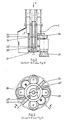
- the control block A is adjoined at the bottom by the cylindrical housing 17 of the drive upper part B, the head 2 of the tool carrier shaft 1 being rotatably guided axially and radially in a long bearing combination 3 designed for the blown air supply 4.
- the tool carrier shaft head 2 passes through the drive carrier plate 5 and is then, i.e. arranged underneath, positively connected to a spur gear 6, the sprocket 7 engaging in this spur gear 6 also the pinion 7, which is also arranged below the drive carrier plate 5, axially parallel to the tool carrier shaft 1 and is driven by a compressed air lamella motor 8 installed on the drive carrier plate 5.
- the lifting cam 9 is provided axially parallel to the tool carrier shaft 1 for the engagement of a lifting lug 10 on the drive carrier plate 5, which is pivotally connected to the head of the piston rod 12 of the lifting cylinder 11 and initially engages in the lifting cam 9 in a form-fitting manner.
- the drive carrier plate 5 is guided in cylindrical columns 13 arranged axially parallel to the tool carrier shaft 1.
- the essential parts of the drive are arranged in the housing 17 via a large lockable
- Commissioning usually takes place after the lower drive part D (ie the guide tube) has been moved into the RPV cover, an intermediate piece C described later being flanged between the lower drive part D and the upper drive part B, which is supported via the flange 37 of the lower drive part D described later .
- the further commissioning is effected by the actuation of the lifting cylinder 11, which in turn causes a roller lever 15 to actuate the directional control valve switch "engine start-clockwise rotation” and "blown air on” in the course of its stroke.
- the lifting cylinder 11 guides the drive carrier plate 5 downwards until the brush head E engages in the thread in the RPV, in which position the stroke path of the piston rod 12 of the lifting cylinder 11, which is controlled by a linkage 16, swings the lifting lug 10 out of the lifting cam 9 and thus the further movement of the tool carrier shaft 1 releases.
- the tool carrier shaft 1 is now moved independently of the lifting cylinder 11 by positive locking between the brush head E carried by it with the thread to be cleaned, i.e. the brush head E is screwed into the thread.
- the screw-in path of the brush head E generally corresponds to the thread length, the lowest point being determined by a lower roller lever 15 'for actuating the directional control valve switches "motor stop” and "motor start anticlockwise rotation”.
- a rope pulleys 19 and 19 in the cylindrical housing 17 of the upper drive part B In order to relieve the brush elements due to the weight of the drive unit 8/5/6/7 etc., as well as the tool carrier shaft 1 and parts of the suction device, in particular when the brush head E is being raised, there is a rope pulleys 19 and 19 in the cylindrical housing 17 of the upper drive part B. 'Integrated counterweight 18 integrated, the position of the weight 18 is fixed within the housing 17 in its axial direction by guide columns 18'.
- a rope pulley 19 is connected to the upper end flange 20 of the housing 17 and a rope pulley 19 'to the lower end flange 20' of the housing 17 and to the counterweight 18 via a rope 19 "with the parts to be relieved.
- the counterweight 18 is a molded body that spares the drive parts, exhaust air ducts, etc.
- the blown air duct 4 opens into the annular space 3 'formed by the long bearing combination 3.
- the long bearing combination 3 is connected to the drive carrier plate 5.
- the head 2 of the tool carrier shaft 1 is axially and radially guided in this long bearing combination 3.
- the compressed air is guided via a control valve into the annular space 3 ′ given there and enters through radially directed bores 21 into a bore 22 directed centrally through the tool carrier shaft head 2, the head 2 into a bore connected to it Transferred precision steel tube 23, which essentially forms the tool carrier shaft 1.
- the tool carrier shaft 1 leads into an end piece 24 delimited by flange 25, the flange 25 also being the carrier of the casing tube 26 for the exhaust air supply described later.
- the tool carrier shaft 1 can be separated in the intermediate piece C by a coupling 27.
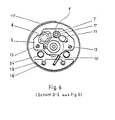
- the actual brush head E is connected to the flange 25 and generally has four radially directed round brushes 28 and two plate brushes 29 axially directed against the thread root in the RPV.
- the air is guided centrally in this area.
- the blown air enters from here radially in two superimposed planes annular channels 30 and 30 ', which are open in the area of the radially directed round brushes 28, and enters the threads via additional directional nozzles 30 ".
- the axial continuation of this central blown air supply tapers against the nozzle-shaped end, this end 31 leading the blown air against the bottom of the blind hole thread of the RPV.
- this brush head E another head can be put on, this one consists of felt disks 40 corresponding to the thread, which are generally impregnated with molykote.
- the suction serves to remove the dirt particles cleaned from the threads and it connects to the control block A and leads further through the cylindrical housing 17 of the upper drive part B, through the intermediate piece C, through the lower drive part D designed as a guide tube and from there into the Tool jacket shaft 1 comprising a suction jacket pipe 26, in order to ultimately open into two suction ports 32 connected to the brush head E and the tool table shaft 1.
- the rotating suction jacket tube 26 opens in the direction of suction in the lower drive part D into a non-rotating exhaust air collection chamber 33 which is adjustable in its axial direction, and which seals against it.
- the actual tool carrier shaft 1 leads in the further passage through this chamber 33 and emerges from it together with the chamber 33 in an axially displaceable manner and is sealed against it.
- Fixed exhaust pipes 34 are connected to the exhaust air collection chamber 33, each of which is designed as a telescopic cable 35 leading upwards.
- the tubes end in the lower limiting flange 36 of the intermediate piece C leading to the upper drive part B.
- the intermediate piece C is based on a flange 37 which is claw-shaped on one side, which acts as a torque support against the RPV cover.
- two suction pipes 34 lead from the exhaust air collection chamber 33 through the lower drive part D into the intermediate piece C.
- the respective opening area of the respective suction pipe 34 is connected via a detachable hose connection 38 to the suction pipe 34 'leading through the upper drive part B, respectively.
- the intermediate piece C the upper part of the tool carrier shaft 1 can also be separated from the lower part thereof by the coupling 27.
- the intermediate piece C is provided with a mounting cover 39, so that from here the tool carrier shaft 1 can be separated and replacement parts can be installed.
- the hose connections 38 of the suction pipes 34/34 ' can be removed, so that from here each suction pipe 34, e.g. by ejecting it with suitable aids.
- the suction pipes 34 ' are connected to the plant network by B and A and the extracted air is cleaned in suitable filters.
- This machine can also be used to clean dismantled nuts on a separate parking ring.
- the flexible suction line on control block A is removed.
- the suction then takes place via an adapter 41 which engages over the nut and to which a modified suction line 42, which also leads to a filter device, is connected at the bottom.
- the workplace is ventilated here via the exposed suction lines.
- a second idler pinion 7 'engaging in the spur gear 6 is provided, which can be driven by means of a crank handle 7 "working platform which engages through the drive carrier plate 5. The brush head E can thus be screwed back manually.
Landscapes
- Engineering & Computer Science (AREA)
- Mechanical Engineering (AREA)
- Cleaning In General (AREA)
Claims (6)
une partie inférieure (D) de commande en même temps formant le tuyau de guidage pour le passage à travers du couvercle du récipient sous pression d'un réacteur et la longueur de laquelle correspondant à l'épaisseur de la bride supérieure et limitant duquel dirigée vers la pièce intercalaire (C) s'étendant unilatéralement sous forme patte sur le couvercle du récipient sous pression d'un réacteur et étant formée comme soutient du moment de torsion; et
dans la zone de transition au tuyau de guidage propre, un joint (14) isolé contre le couvercle du récipient sous pression d'un réacteur et un moyen d'aspiration (33/34/35) mobile et guidé dans une manière isolée dans la partie inférieure (D) de commande dans une manière correspondante au chemin d'extraction et de retraite, et que l'arbre de porte-outil (1) rotant, par commande mécanique entre la tête de brosse (E) portée par lui et le filet à nettoyer est mouvé vers le bas jusqu'à ce qu'un deuxième interrupteur à diverses voies commande "moteur stop" et "moteur mis en marche course à gauche", et la tête de brosse (E) maintenant se visse vers le haut jusqu'à ce qu'elle se rembraye avec le cylindre de levage (11).
Applications Claiming Priority (2)
| Application Number | Priority Date | Filing Date | Title |
|---|---|---|---|
| DE19813135882 DE3135882C2 (de) | 1981-09-10 | 1981-09-10 | Vorrichtung zur Abreinigung von Sacklochgewinden in Reaktor-Druckbehältern (RDB) bei abgenommenem oder aufliegendem Reaktordeckel |
| DE3135882 | 1981-09-10 |
Publications (3)
| Publication Number | Publication Date |
|---|---|
| EP0075155A2 EP0075155A2 (fr) | 1983-03-30 |
| EP0075155A3 EP0075155A3 (en) | 1983-07-27 |
| EP0075155B1 true EP0075155B1 (fr) | 1986-04-09 |
Family
ID=6141322
Family Applications (1)
| Application Number | Title | Priority Date | Filing Date |
|---|---|---|---|
| EP19820108082 Expired EP0075155B1 (fr) | 1981-09-10 | 1982-09-02 | Procédé pour le nettoyage de filets de trous borgnes d'un récipient sous pression d'un réacteur, le couvercle du réacteur étant monté ou démonté, par une machine à nettoyer, ainsi que machine pour la mise en oeuvre du procédé |
Country Status (2)
| Country | Link |
|---|---|
| EP (1) | EP0075155B1 (fr) |
| DE (1) | DE3135882C2 (fr) |
Families Citing this family (7)
| Publication number | Priority date | Publication date | Assignee | Title |
|---|---|---|---|---|
| DE3332881A1 (de) * | 1983-09-13 | 1985-03-28 | Nico Industriereinigung AG, Luzern | Verfahren und vorrichtung zum dekontaminieren radioaktiv verschmutzter metallprofile |
| DE19509019C2 (de) * | 1995-03-13 | 1997-03-27 | Siemens Ag | Vorrichtung zum Bearbeiten eines Gewindesackloches |
| DE102018118131B3 (de) * | 2018-07-26 | 2019-11-07 | Siempelkamp NIS Ingenieurgesellschaft mbH | Reinigungsvorrichtung und Verfahren zum Reinigen eines Innengewindes einer Deckelverschraubung eines Reaktordruckbehälters |
| DE102018118136B3 (de) * | 2018-07-26 | 2019-10-10 | Siempelkamp NIS Ingenieurgesellschaft mbH | Schaberkopf und Schaberreinigung |
| DE102018118145B4 (de) * | 2018-07-26 | 2020-08-06 | Siempelkamp NIS Ingenieurgesellschaft mbH | Bürstenkopf, Deckelverschraubung und Verfahren zum Reinigen eines Innengewindes einer Deckelverschraubung |
| CN111843586A (zh) * | 2020-08-18 | 2020-10-30 | 苏州麻雀智能科技有限公司 | 机床智能制造单元 |
| CN117680399A (zh) * | 2023-12-15 | 2024-03-12 | 鹤山市精工制版有限公司 | 一种版辊辊面清洁装置 |
Family Cites Families (6)
| Publication number | Priority date | Publication date | Assignee | Title |
|---|---|---|---|---|
| DE1657181A1 (de) * | 1968-02-09 | 1971-02-11 | Willi Leise | Vorrichtung zum Reinigen von Bierglaesern |
| SE400024B (sv) * | 1976-02-11 | 1978-03-13 | Wennberg Flex Ake Ab | Suganordning for direkt evakuering av fororeningar fran fororeningsalstrande verktyg i en arbetslokal |
| DE2606214C3 (de) * | 1976-02-17 | 1980-11-27 | Lothar A. 7141 Hochdorf Voigt | Gerät zum Reinigen der Gewindegänge von Schraubbolzen |
| FR2355578A1 (fr) * | 1976-06-23 | 1978-01-20 | Rousselin Jean | Procede et dispositif pour enlever des substances polluantes deposees sur des surfaces |
| DE2732882C3 (de) * | 1977-07-21 | 1980-05-22 | Ntg Nukleartechnik Gmbh U. Partner, 6460 Gelnhausen | Einrichtung zur Reinigung des Innengewindes von Muttern |
| DE2948006A1 (de) * | 1979-11-29 | 1981-06-04 | Jürgen 4477 Welver Volkmann | Verfahren und vorrichtung zum entfernen fester oder fluessigerrueckstaende aus hohlraeumen wie bohrungen o.dgl. |
-
1981
- 1981-09-10 DE DE19813135882 patent/DE3135882C2/de not_active Expired
-
1982
- 1982-09-02 EP EP19820108082 patent/EP0075155B1/fr not_active Expired
Also Published As
| Publication number | Publication date |
|---|---|
| EP0075155A2 (fr) | 1983-03-30 |
| DE3135882C2 (de) | 1984-12-20 |
| EP0075155A3 (en) | 1983-07-27 |
| DE3135882A1 (de) | 1983-03-31 |
Similar Documents
| Publication | Publication Date | Title |
|---|---|---|
| DE69621585T2 (de) | Vorrichtung zum auswechseln von brennern | |
| EP1785222B1 (fr) | Cylindre de serrage rapide comprenant un mécanisme de guidage du boulon de serrage | |
| DE1757370A1 (de) | Gasfilter | |
| DE3421885C2 (de) | Verfahren zum Reinigen der Gasdüse eines Schweißbrenners sowie Gerät zur Durchführung des Verfahrens | |
| EP0878241A2 (fr) | Installation de captation de la poudre excédentaire lors du revêtement par poudrage de pièces | |
| EP0075155B1 (fr) | Procédé pour le nettoyage de filets de trous borgnes d'un récipient sous pression d'un réacteur, le couvercle du réacteur étant monté ou démonté, par une machine à nettoyer, ainsi que machine pour la mise en oeuvre du procédé | |
| DE2831687A1 (de) | Einrichtung zum reinigen der steigerohre von koksofenbatterien | |
| DE102014011133A1 (de) | Schleuderstation und Druckluftreinigungsanordnung | |
| DE3142849C2 (fr) | ||
| CH656151A5 (de) | Anodenstangenreinigungsmaschine. | |
| DE2254525A1 (de) | Vorrichtung zum saeubern, ent-, verputzen und bemalen der aussenfassaden von bauwerken | |
| DE3730438C2 (fr) | ||
| DE202008017291U1 (de) | Reinigungsvorrichtung für Lukos o.dgl. Wärmetauscher | |
| EP0130373A2 (fr) | Méthode et dispositif pour la réparation des axes de tiroir | |
| DE69000540T2 (de) | Vorrichtung zum reinigen von gebaeudefassaden. | |
| EP0172556B1 (fr) | Dispositif de filage pour fibres synthétiques contenant une cheminée à partie supérieure télescopique | |
| DE68928623T2 (de) | Filtrierungseinrichtung, die eine pumpe enthält | |
| DE2606214A1 (de) | Geraet zum reinigen von gewindegaengen | |
| AT393687B (de) | Vorrichtung zum reinigen der tueren von koksofenbatterien | |
| DE102022121596A1 (de) | Vorrichtung zum Betreiben eines Wasserspiels | |
| DE3616112A1 (de) | Vorrichtung zur reinigung von brunnenschaechten und brunnenrohren | |
| DE102021121654B3 (de) | Pumpenvorrichtung, Verfahren zur Durchführung eines Service bei einer Pumpenvorrichtung | |
| DE3223727C2 (de) | Hubantriebsvorrichtung für Greiferrechen | |
| DE3439653C1 (de) | Vorrichtung zum Verbinden eines Bohrstranges mit einem Rohr od.dgl. | |
| DE2500067A1 (de) | Rechenreinigungsanlage fuer stroemende gewaesser, insbesondere fuer zulaeufe von klaeranlagen |
Legal Events
| Date | Code | Title | Description |
|---|---|---|---|
| PUAI | Public reference made under article 153(3) epc to a published international application that has entered the european phase |
Free format text: ORIGINAL CODE: 0009012 |
|
| AK | Designated contracting states |
Designated state(s): BE CH FR GB IT LI SE |
|
| PUAL | Search report despatched |
Free format text: ORIGINAL CODE: 0009013 |
|
| AK | Designated contracting states |
Designated state(s): BE CH FR GB IT LI SE |
|
| 17P | Request for examination filed |
Effective date: 19840127 |
|
| GRAA | (expected) grant |
Free format text: ORIGINAL CODE: 0009210 |
|
| AK | Designated contracting states |
Kind code of ref document: B1 Designated state(s): BE CH FR GB IT LI SE |
|
| ITF | It: translation for a ep patent filed | ||
| ET | Fr: translation filed | ||
| RAP2 | Party data changed (patent owner data changed or rights of a patent transferred) |
Owner name: NTG NUKLEARTECHNIK GMBH & CO. KG |
|
| BECN | Be: change of holder's name |
Effective date: 19861001 |
|
| PLBI | Opposition filed |
Free format text: ORIGINAL CODE: 0009260 |
|
| 26 | Opposition filed |
Opponent name: KRAFTWERK UNION AKTIENGESELLSCHAFT Effective date: 19870108 |
|
| REG | Reference to a national code |
Ref country code: CH Ref legal event code: PFA Free format text: NTG NEUE TECHNOLOGIEN GMBH & CO. KG |
|
| RAP2 | Party data changed (patent owner data changed or rights of a patent transferred) |
Owner name: NTG NEUE TECHNOLOGIEN GMBH & CO. KG |
|
| PLAB | Opposition data, opponent's data or that of the opponent's representative modified |
Free format text: ORIGINAL CODE: 0009299OPPO |
|
| PLAB | Opposition data, opponent's data or that of the opponent's representative modified |
Free format text: ORIGINAL CODE: 0009299OPPO |
|
| R26 | Opposition filed (corrected) |
Opponent name: SIEMENS AKTIENGESELLSCHAFT, BERLIN UND MUENCHEN Effective date: 19870108 |
|
| R26 | Opposition filed (corrected) |
Opponent name: SIEMENS AKTIENGESELLSCHAFT, BERLIN UND MUENCHEN Effective date: 19870108 |
|
| PG25 | Lapsed in a contracting state [announced via postgrant information from national office to epo] |
Ref country code: LI Effective date: 19890930 Ref country code: CH Effective date: 19890930 Ref country code: BE Effective date: 19890930 |
|
| PLBN | Opposition rejected |
Free format text: ORIGINAL CODE: 0009273 |
|
| STAA | Information on the status of an ep patent application or granted ep patent |
Free format text: STATUS: OPPOSITION REJECTED |
|
| 27O | Opposition rejected |
Effective date: 19890806 |
|
| BERE | Be: lapsed |
Owner name: NTG NEUE TECHNOLOGIEN G.M.B.H. & CO. K.G. Effective date: 19890930 |
|
| PG25 | Lapsed in a contracting state [announced via postgrant information from national office to epo] |
Ref country code: FR Effective date: 19900531 |
|
| REG | Reference to a national code |
Ref country code: CH Ref legal event code: PL |
|
| REG | Reference to a national code |
Ref country code: FR Ref legal event code: ST |
|
| PGFP | Annual fee paid to national office [announced via postgrant information from national office to epo] |
Ref country code: SE Payment date: 19900925 Year of fee payment: 9 |
|
| PGFP | Annual fee paid to national office [announced via postgrant information from national office to epo] |
Ref country code: GB Payment date: 19901012 Year of fee payment: 9 |
|
| PG25 | Lapsed in a contracting state [announced via postgrant information from national office to epo] |
Ref country code: GB Effective date: 19910902 |
|
| PG25 | Lapsed in a contracting state [announced via postgrant information from national office to epo] |
Ref country code: SE Effective date: 19910903 |
|
| GBPC | Gb: european patent ceased through non-payment of renewal fee | ||
| EUG | Se: european patent has lapsed |
Ref document number: 82108082.7 Effective date: 19920408 |