EP0075310A1 - Circuit pour centrales de télécommunications, en particulier centrales téléphoniques, avec des dispositifs pour assurer la sécurité de la transmission de signaux codés - Google Patents
Circuit pour centrales de télécommunications, en particulier centrales téléphoniques, avec des dispositifs pour assurer la sécurité de la transmission de signaux codés Download PDFInfo
- Publication number
- EP0075310A1 EP0075310A1 EP82108690A EP82108690A EP0075310A1 EP 0075310 A1 EP0075310 A1 EP 0075310A1 EP 82108690 A EP82108690 A EP 82108690A EP 82108690 A EP82108690 A EP 82108690A EP 0075310 A1 EP0075310 A1 EP 0075310A1
- Authority
- EP
- European Patent Office
- Prior art keywords
- information
- complement
- comparator
- stored
- line
- Prior art date
- Legal status (The legal status is an assumption and is not a legal conclusion. Google has not performed a legal analysis and makes no representation as to the accuracy of the status listed.)
- Granted
Links
Images
Classifications
-
- H—ELECTRICITY
- H04—ELECTRIC COMMUNICATION TECHNIQUE
- H04L—TRANSMISSION OF DIGITAL INFORMATION, e.g. TELEGRAPHIC COMMUNICATION
- H04L1/00—Arrangements for detecting or preventing errors in the information received
- H04L1/12—Arrangements for detecting or preventing errors in the information received by using return channel
- H04L1/14—Arrangements for detecting or preventing errors in the information received by using return channel in which the signals are sent back to the transmitter to be checked ; echo systems
-
- H—ELECTRICITY
- H04—ELECTRIC COMMUNICATION TECHNIQUE
- H04Q—SELECTING
- H04Q11/00—Selecting arrangements for multiplex systems
- H04Q11/04—Selecting arrangements for multiplex systems for time-division multiplexing
Definitions
- Circuit arrangement for telecommunication switching systems in particular telephone switching systems, in which binary-coded information is transmitted via lines each having a line core per code element, and in which transmitted information is both stored at the transmitting point and fed to a comparator and is also received back after being transmitted via the line, and in which the comparator receives the information received and compares it with the stored information, and in which the information and a complement formed by inverting it are used to increase the security of the monitoring and the comparison is based on the information and the complement.
- German Offenlegungsschrift 2,423,260 The basic concept that is decisive for a circuit arrangement of this type is already known from German Offenlegungsschrift 2,423,260.
- the address of one of a plurality of individual devices is then sent out for testing purposes and returned to the sending device by the relevant individual device.
- the inverted address is sent to the controlled individual device and returned to the sending device by the individual device.
- the transmitted address with the returned address and the transmitted inverted address with the returned inverted address are ver like. Furthermore, comparisons are made, on the one hand between the sent address and the returned inverted address and between the sent inverted address and the returned address.
- the known method makes it possible to detect and localize errors on the message paths used for the transmission and retransmission of the addresses and the inverted addresses, as well as errors in decoding devices and coding devices in the individual devices, and in the transmitting device which carries out the indicated check .
- the object of the invention is to specify a circuit arrangement in which a simplified method compared to the known method is implemented and which offers favorable conditions for carrying out frequently recurring control processes.
- the 'invention achieves the object in that the information representing the constantly recurring standard instructions is stored individually together with its complement in a coherent series of storage units in an instruction memory, in that when information is transmitted via the line of the comparator, the information and its complement after Receipt, in particular after a buffering, is inverted and the information and the bits forming the complement are shifted, as a result of which both swap places within the comparator, and that the comparator compares the result of this inversion and shift with the information obtained and, if necessary, with the the received complement is checked for coincidence.
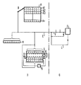
- a sending device D hereinafter referred to as “command transmitter”
- a receiving device G hereinafter referred to as “command receiver”
- message bus C This is used to transmit multi-digit binary-coded control commands.
- the message bus may have eight line wires for the transmission of 8-bit information.
- a number of memory lines A1 to An are provided in an instruction memory A. Each of these lines of memory is equipped with eight memory locations for storing 8-bit information, as can be seen from the drawing. Likewise, a buffer Y, which is also connected to the message bus C, has eight storage locations. Registers U and W of a comparator V each have eight storage locations.
- One control command per memory line is permanently stored in memory lines A1 to An.
- the command generator D uses a reading device B to control one memory line of the command memory A and to transmit the control command stored therein in a manner known per se via the message bus C.
- the individual bits of the control command reach a plurality of receiving devices in the command receiver G via the message bus C.
- the message bus C branches in an inner line system F of the command receiver G.
- One of the receiving devices in the command receiver G is indicated and labeled "F". After receiving a control command, this receiving device returns what it has received via a line loop L to the central message bus C, via which the originally sent control command is thus returned from the command receiver G to the command generator D.
- the returned control command agrees with the transmitted control command, provided that the process of transmitting the control command including the reading process on the part of the reading device B, the receiving process in the received device E, the return process on the part thereof and a receiving process on the part of the comparator V using its register U are error-free has expired.
- the comparator V with its registers U and W as well as with its inverter T and with a shifting device X is used to monitor an error-free sequence of the transmission processes of each of the control commands.
- a buffer Y is also used for this purpose.
- a control command actually only consists of 4-bit information. This is stored in the left part of each of the memory lines A1 to An. The complement of the control command is stored in the right part of each of these memory lines. A control command and its complement are therefore always stored together in one memory line. The complement of a control command is formed by inverting it in a manner known per se.
- the reader B is set to the relevant memory line, for example A1, of the command memory A, as already stated, for this purpose.
- the individual bits of the control command and its complement are sent out via the individual line wires of the message bus C and received by the receiving device E.
- the control command and complement also go to a buffer Y, which also contains 8-bit information is seen.
- the four bits of the control command are in the left part of the inverter T and the four bits of the complement of the control command in the right part of the inverter T.
- the inverter T then gives the inversion of the control command and the inversion of the complement continue to a register W, which is designed as a shift register.
- the inversion of the control command is now in the left part of this shift register and the inversion of the complement in the right part.
- a displacement device X carries out an exchange. It shifts each bit of the total information stored in the shift register W to the right by four storage locations.
- the invention can be implemented with very simple means, in particular with the use of switching means required for issuing control commands.
- the correct functioning of the comparator which monitors the error-free execution of the transmission processes, is also subject to this monitoring.
Landscapes
- Engineering & Computer Science (AREA)
- Computer Networks & Wireless Communication (AREA)
- Signal Processing (AREA)
- Detection And Prevention Of Errors In Transmission (AREA)
- Pharmaceuticals Containing Other Organic And Inorganic Compounds (AREA)
- Nitrogen And Oxygen Or Sulfur-Condensed Heterocyclic Ring Systems (AREA)
- Monitoring And Testing Of Exchanges (AREA)
- Data Exchanges In Wide-Area Networks (AREA)
- Hardware Redundancy (AREA)
- Communication Control (AREA)
Priority Applications (1)
| Application Number | Priority Date | Filing Date | Title |
|---|---|---|---|
| AT82108690T ATE17978T1 (de) | 1981-09-23 | 1982-09-20 | Schaltungsanordnung fuer f ernmeldevermittlungsanlagen, insbesondere fernsprechvermittlungsanlagen, mit einrichtungen zur sicherung der uebertragung codierter signale. |
Applications Claiming Priority (2)
| Application Number | Priority Date | Filing Date | Title |
|---|---|---|---|
| DE3137904A DE3137904C2 (de) | 1981-09-23 | 1981-09-23 | Schaltungsanordnung für Fernmeldevermittlungsanlagen, insbesondere Fernsprechvermittlungsanlagen, mit Einrichtungen zur Sicherung der Übertragung codierter Signale |
| DE3137904 | 1981-09-23 |
Publications (2)
| Publication Number | Publication Date |
|---|---|
| EP0075310A1 true EP0075310A1 (fr) | 1983-03-30 |
| EP0075310B1 EP0075310B1 (fr) | 1986-02-12 |
Family
ID=6142435
Family Applications (1)
| Application Number | Title | Priority Date | Filing Date |
|---|---|---|---|
| EP82108690A Expired EP0075310B1 (fr) | 1981-09-23 | 1982-09-20 | Circuit pour centrales de télécommunications, en particulier centrales téléphoniques, avec des dispositifs pour assurer la sécurité de la transmission de signaux codés |
Country Status (5)
| Country | Link |
|---|---|
| EP (1) | EP0075310B1 (fr) |
| JP (1) | JPS5868344A (fr) |
| AT (1) | ATE17978T1 (fr) |
| DE (1) | DE3137904C2 (fr) |
| FI (1) | FI75073C (fr) |
Cited By (5)
| Publication number | Priority date | Publication date | Assignee | Title |
|---|---|---|---|---|
| EP0158131A1 (fr) * | 1984-03-16 | 1985-10-16 | THE PLESSEY COMPANY plc | Interface de commande d'une unité de terminaison de ligne numérique |
| EP0335424A3 (fr) * | 1988-03-31 | 1991-04-10 | Wang Laboratories, Inc. | Dispositif de vérification de parité |
| FR2735641A1 (fr) * | 1995-06-15 | 1996-12-20 | Mitsubishi Electric Corp | Procede de commande de communication et dispositif de communication |
| EP0770962A3 (fr) * | 1989-06-29 | 1997-07-02 | Symbol Technologies Inc | Système de communication à paquet de données |
| GB2313747A (en) * | 1996-05-30 | 1997-12-03 | Motorola Ltd | Data transmission verification |
Families Citing this family (2)
| Publication number | Priority date | Publication date | Assignee | Title |
|---|---|---|---|---|
| DE3723115C1 (en) * | 1987-07-13 | 1989-03-16 | Telefonbau & Normalzeit Gmbh | Test and measuring device for digital signals |
| DE4332145A1 (de) * | 1993-09-17 | 1995-03-23 | Siemens Ag | Verfahren zur einkanaligen Übertragung von Datentelegrammen und Einrichtung zur Durchführung des Verfahrens |
Citations (6)
| Publication number | Priority date | Publication date | Assignee | Title |
|---|---|---|---|---|
| FR1583211A (fr) * | 1968-04-18 | 1969-10-24 | ||
| US3523279A (en) * | 1968-04-17 | 1970-08-04 | Bell Telephone Labor Inc | Data transmission error checking arrangement |
| DE2423260A1 (de) * | 1974-05-14 | 1975-11-20 | Siemens Ag | Verfahren und schaltungsanordnung zur pruefung von daten verarbeitenden anlagen, insbesondere fernsprechvermittlungsanlagen mit ueber ein busleitungssystem an eine steuerzentrale angeschlossenen peripheren einrichtungen |
| FR2298911A1 (fr) * | 1975-01-22 | 1976-08-20 | Leinfellner Helmut | Dispositif de codage et de decodage pour installations de transmission |
| DE2727533A1 (de) * | 1976-06-18 | 1977-12-22 | Ncr Co | Datenuebertragungssystem |
| GB2032736A (en) * | 1978-10-24 | 1980-05-08 | Standard Telephones Cables Ltd | Data transfer system |
Family Cites Families (1)
| Publication number | Priority date | Publication date | Assignee | Title |
|---|---|---|---|---|
| JPS5437783B2 (fr) * | 1973-12-25 | 1979-11-16 |
-
1981
- 1981-09-23 DE DE3137904A patent/DE3137904C2/de not_active Expired
-
1982
- 1982-09-20 AT AT82108690T patent/ATE17978T1/de not_active IP Right Cessation
- 1982-09-20 EP EP82108690A patent/EP0075310B1/fr not_active Expired
- 1982-09-22 JP JP57164198A patent/JPS5868344A/ja active Pending
- 1982-09-22 FI FI823258A patent/FI75073C/fi not_active IP Right Cessation
Patent Citations (6)
| Publication number | Priority date | Publication date | Assignee | Title |
|---|---|---|---|---|
| US3523279A (en) * | 1968-04-17 | 1970-08-04 | Bell Telephone Labor Inc | Data transmission error checking arrangement |
| FR1583211A (fr) * | 1968-04-18 | 1969-10-24 | ||
| DE2423260A1 (de) * | 1974-05-14 | 1975-11-20 | Siemens Ag | Verfahren und schaltungsanordnung zur pruefung von daten verarbeitenden anlagen, insbesondere fernsprechvermittlungsanlagen mit ueber ein busleitungssystem an eine steuerzentrale angeschlossenen peripheren einrichtungen |
| FR2298911A1 (fr) * | 1975-01-22 | 1976-08-20 | Leinfellner Helmut | Dispositif de codage et de decodage pour installations de transmission |
| DE2727533A1 (de) * | 1976-06-18 | 1977-12-22 | Ncr Co | Datenuebertragungssystem |
| GB2032736A (en) * | 1978-10-24 | 1980-05-08 | Standard Telephones Cables Ltd | Data transfer system |
Cited By (6)
| Publication number | Priority date | Publication date | Assignee | Title |
|---|---|---|---|---|
| EP0158131A1 (fr) * | 1984-03-16 | 1985-10-16 | THE PLESSEY COMPANY plc | Interface de commande d'une unité de terminaison de ligne numérique |
| EP0335424A3 (fr) * | 1988-03-31 | 1991-04-10 | Wang Laboratories, Inc. | Dispositif de vérification de parité |
| US5155735A (en) * | 1988-03-31 | 1992-10-13 | Wang Laboratories, Inc. | Parity checking apparatus with bus for connecting parity devices and non-parity devices |
| EP0770962A3 (fr) * | 1989-06-29 | 1997-07-02 | Symbol Technologies Inc | Système de communication à paquet de données |
| FR2735641A1 (fr) * | 1995-06-15 | 1996-12-20 | Mitsubishi Electric Corp | Procede de commande de communication et dispositif de communication |
| GB2313747A (en) * | 1996-05-30 | 1997-12-03 | Motorola Ltd | Data transmission verification |
Also Published As
| Publication number | Publication date |
|---|---|
| FI823258L (fi) | 1983-03-24 |
| ATE17978T1 (de) | 1986-02-15 |
| EP0075310B1 (fr) | 1986-02-12 |
| FI75073B (fi) | 1987-12-31 |
| FI823258A0 (fi) | 1982-09-22 |
| DE3137904C2 (de) | 1985-10-31 |
| JPS5868344A (ja) | 1983-04-23 |
| FI75073C (fi) | 1988-04-11 |
| DE3137904A1 (de) | 1983-04-07 |
Similar Documents
| Publication | Publication Date | Title |
|---|---|---|
| DE3586708T2 (de) | Verfahren zur fehlererkennung und -korrektur durch mehrheitsentscheidung. | |
| DE2518588C3 (de) | Verfahren zur Überwachung der Folgerichtigkeit von Codesignalgruppen in Einrichtungen der Nachrichtentechnik | |
| DE3111447A1 (de) | Anzeigeschaltung fuer speicherschreibfehler | |
| DE19857154C1 (de) | Verfahren zur Datenübertragung | |
| DE2736967A1 (de) | Asynchrone telemetrieschaltung | |
| EP0075310B1 (fr) | Circuit pour centrales de télécommunications, en particulier centrales téléphoniques, avec des dispositifs pour assurer la sécurité de la transmission de signaux codés | |
| DE2131787C3 (de) | Schaltungsanordnung zur Fehlerfeststellung bei Datenverarbeitungssystemen | |
| DE2608435A1 (de) | Vorrichtung zur fehlererkennung und fehlerkorrektur in digitalen datenverarbeitungsanlagen | |
| DE103335T1 (de) | Schaltungsanordnung zum nachrichtenaustausch in einem fernmeldesystem bestehend aus einer mehrzahl von modularen einheiten. | |
| EP0009600B1 (fr) | Procédé et dispositif d'interface pour exécuter des operations de maintenance sur une interface entre un processeur de maintenance et une pluralité d'unités fonctionnelles à vérifier d'un système de traitement de données | |
| EP0029216B1 (fr) | Dispositif pour la transmission de données avec une mémoire-tampon et dispositifs pour la protection des données | |
| DE2507804C1 (de) | Schaltungsanordnung zur Steuerung von Halbduplex-Datenuebertragungsanlagen | |
| DE3821871C2 (fr) | ||
| EP0379625B1 (fr) | Procédé de traitement de mots binaires contrôlables par parité, qui, pendant leur transmission, subissent une atténuation numérique et/ou une conversion de code | |
| DE3328893A1 (de) | Schaltungsanordnung fuer fernmeldeanlagen, insbesondere fernsprechvermittlungsanlagen, mit datensicherung durch paritaetsbits | |
| AT500350A1 (de) | Anlage zum übertragen von daten in einem seriellen, bidirektionalen bus | |
| DE2019795A1 (de) | Datenverarbeitungsanlage mit Ein-Ausgabeeinrichtungen | |
| EP0525921A2 (fr) | Transmission de données avec répétition, un des messages étant crypté | |
| EP0274653B1 (fr) | Méthode pour diagnostiquer et tester un ensemble d'interface | |
| DE1943859C3 (de) | Verfahren und Vorrichtung zur Prüfung und/oder Korrektur von Datenwörtern und/ oder zur Erzeugung von Prüfziffern | |
| DE1932614C3 (de) | Prüfeinrichtung zur Feststellung einer Mehrfachauswahl von Verarbeitungs einheiten in einem Datenverarbeitungs system | |
| EP0029215B1 (fr) | Dispositif pour la transmission de données avec une mémoire-tampon et dispositifs pour la protection des données | |
| DE3342638A1 (de) | Verfahren zur betrieblichen ueberwachung von digitalen uebertragungsstrecken | |
| EP0981258B1 (fr) | Procédure pour le transport numérique de l' information et/ou des données sur une voie de transmission | |
| DE2100887B2 (de) | Verfahren zur Überwachung des Infor mationsinhalts eines Umlaufspeichers |
Legal Events
| Date | Code | Title | Description |
|---|---|---|---|
| PUAI | Public reference made under article 153(3) epc to a published international application that has entered the european phase |
Free format text: ORIGINAL CODE: 0009012 |
|
| AK | Designated contracting states |
Designated state(s): AT CH FR GB LI SE |
|
| 17P | Request for examination filed |
Effective date: 19830927 |
|
| GRAA | (expected) grant |
Free format text: ORIGINAL CODE: 0009210 |
|
| AK | Designated contracting states |
Designated state(s): AT CH FR GB LI SE |
|
| REF | Corresponds to: |
Ref document number: 17978 Country of ref document: AT Date of ref document: 19860215 Kind code of ref document: T |
|
| ET | Fr: translation filed | ||
| PLBE | No opposition filed within time limit |
Free format text: ORIGINAL CODE: 0009261 |
|
| STAA | Information on the status of an ep patent application or granted ep patent |
Free format text: STATUS: NO OPPOSITION FILED WITHIN TIME LIMIT |
|
| 26N | No opposition filed | ||
| PGFP | Annual fee paid to national office [announced via postgrant information from national office to epo] |
Ref country code: AT Payment date: 19890825 Year of fee payment: 8 |
|
| PGFP | Annual fee paid to national office [announced via postgrant information from national office to epo] |
Ref country code: GB Payment date: 19890831 Year of fee payment: 8 |
|
| PGFP | Annual fee paid to national office [announced via postgrant information from national office to epo] |
Ref country code: SE Payment date: 19890912 Year of fee payment: 8 |
|
| PGFP | Annual fee paid to national office [announced via postgrant information from national office to epo] |
Ref country code: FR Payment date: 19890928 Year of fee payment: 8 |
|
| PGFP | Annual fee paid to national office [announced via postgrant information from national office to epo] |
Ref country code: CH Payment date: 19891218 Year of fee payment: 8 |
|
| PG25 | Lapsed in a contracting state [announced via postgrant information from national office to epo] |
Ref country code: GB Effective date: 19900920 Ref country code: AT Effective date: 19900920 |
|
| PG25 | Lapsed in a contracting state [announced via postgrant information from national office to epo] |
Ref country code: SE Effective date: 19900921 |
|
| PG25 | Lapsed in a contracting state [announced via postgrant information from national office to epo] |
Ref country code: LI Effective date: 19900930 Ref country code: CH Effective date: 19900930 |
|
| GBPC | Gb: european patent ceased through non-payment of renewal fee | ||
| PG25 | Lapsed in a contracting state [announced via postgrant information from national office to epo] |
Ref country code: FR Effective date: 19910530 |
|
| REG | Reference to a national code |
Ref country code: CH Ref legal event code: PL |
|
| REG | Reference to a national code |
Ref country code: FR Ref legal event code: ST |
|
| EUG | Se: european patent has lapsed |
Ref document number: 82108690.7 Effective date: 19910527 |