EP0075342A2 - Verschiebbarer Druckkopf - Google Patents
Verschiebbarer Druckkopf Download PDFInfo
- Publication number
- EP0075342A2 EP0075342A2 EP82201043A EP82201043A EP0075342A2 EP 0075342 A2 EP0075342 A2 EP 0075342A2 EP 82201043 A EP82201043 A EP 82201043A EP 82201043 A EP82201043 A EP 82201043A EP 0075342 A2 EP0075342 A2 EP 0075342A2
- Authority
- EP
- European Patent Office
- Prior art keywords
- needles
- recesses
- parts
- row
- support
- Prior art date
- Legal status (The legal status is an assumption and is not a legal conclusion. Google has not performed a legal analysis and makes no representation as to the accuracy of the status listed.)
- Granted
Links
- 239000010979 ruby Substances 0.000 claims abstract description 6
- 229910001750 ruby Inorganic materials 0.000 claims abstract description 6
- 238000006073 displacement reaction Methods 0.000 claims description 6
- 238000004026 adhesive bonding Methods 0.000 description 1
- 238000010276 construction Methods 0.000 description 1
- 230000004048 modification Effects 0.000 description 1
- 238000012986 modification Methods 0.000 description 1
- 230000000717 retained effect Effects 0.000 description 1
Images
Classifications
-
- B—PERFORMING OPERATIONS; TRANSPORTING
- B41—PRINTING; LINING MACHINES; TYPEWRITERS; STAMPS
- B41J—TYPEWRITERS; SELECTIVE PRINTING MECHANISMS, i.e. MECHANISMS PRINTING OTHERWISE THAN FROM A FORME; CORRECTION OF TYPOGRAPHICAL ERRORS
- B41J25/00—Actions or mechanisms not otherwise provided for
- B41J25/001—Mechanisms for bodily moving print heads or carriages parallel to the paper surface
-
- B—PERFORMING OPERATIONS; TRANSPORTING
- B41—PRINTING; LINING MACHINES; TYPEWRITERS; STAMPS
- B41J—TYPEWRITERS; SELECTIVE PRINTING MECHANISMS, i.e. MECHANISMS PRINTING OTHERWISE THAN FROM A FORME; CORRECTION OF TYPOGRAPHICAL ERRORS
- B41J2/00—Typewriters or selective printing mechanisms characterised by the printing or marking process for which they are designed
- B41J2/22—Typewriters or selective printing mechanisms characterised by the printing or marking process for which they are designed characterised by selective application of impact or pressure on a printing material or impression-transfer material
- B41J2/23—Typewriters or selective printing mechanisms characterised by the printing or marking process for which they are designed characterised by selective application of impact or pressure on a printing material or impression-transfer material using print wires
- B41J2/235—Print head assemblies
- B41J2/25—Print wires
- B41J2/255—Arrangement of the print ends of the wires
-
- B—PERFORMING OPERATIONS; TRANSPORTING
- B41—PRINTING; LINING MACHINES; TYPEWRITERS; STAMPS
- B41J—TYPEWRITERS; SELECTIVE PRINTING MECHANISMS, i.e. MECHANISMS PRINTING OTHERWISE THAN FROM A FORME; CORRECTION OF TYPOGRAPHICAL ERRORS
- B41J25/00—Actions or mechanisms not otherwise provided for
- B41J25/001—Mechanisms for bodily moving print heads or carriages parallel to the paper surface
- B41J25/005—Mechanisms for bodily moving print heads or carriages parallel to the paper surface for serial printing movements superimposed to character- or line-spacing movements
Definitions
- Switchable needle writing heads comprising at least two rows of needles, these needles being slidably mounted in guide paths in a support in two parts, these rows being arranged substantially vertically with respect to the direction d writing a line by the head, means allowing at will to produce a relative displacement between the two parts of the support to align the positions of the needles of one row relative to the positions of the needles of another row parallel to the direction of writing, or shift these positions between the two rows (see USA patent N ° 4,010,835).
- the object of the present invention is to provide a needle head of this type, the construction of which is very precise while being simple to produce.
- the writing head according to the invention is characterized in that the two parts of the support have two faces arranged opposite one another, one of these faces having recesses parallel to each other and of substantially semi-circular section, with a radius corresponding to that of the needles and allowing the latter to slide freely, the needles of a row being placed in these recesses and retained in the latter by a hollow portion of the other part , this hollow portion having a length substantially equal to the length of this row of needles.
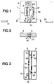
- This support has guide paths for two rows of needles, these paths being produced in an industrial ruby 4 which is shown on a larger scale in FIG. 3 and which comprises a fixed part 5 and a mobile part 6, the latter being mounted on the sliding part 3.
- Part 3 is guided on part 2 by two tabs 7 and 8 of part 2, which are engaged in two recesses 9 and 10 in part 3.
- the latter also carries a finger 11 intended to control its movement by compared to part 2.
- the part 5 of the ruby 4 is itself made up of two parts 12 and 13 assembled by gluing 14.
- Piece 5 has a series of nine parallel recesses 15 of substantially semi-circular section and constituting guide paths for the needles 16 of a first row of needles.
- the part 13 also has a series of parallel recesses 17 arranged opposite the recesses 15, the section of which is arched so as to match the circular section of the needles 16, while leaving a play of a few hundredths of a millimeter to allow free sliding of the needles 16 in their respective guide paths.
- Guide paths are provided between the part 13 and the part 3 to receive a second row of needles 18.
- the needles of this second row can be moved vertically as a block with reference to FIG. 3 to be moved so as to be offset relative to the needles 16 of the first row, taking account of the writing direction A.
- the needles 18 can be brought into a position aligned with the needles 16 in the direction A.
- a fast writing position is obtained when the needles 16 and 18 are aligned, since it is possible on the same line to carry out per unit of time, a double number of stitches than in the case where there is only one row of needles.
- the writing speed remains the same as if there was only one row of needles, but the quality is better since it is possible to obtain an overlap points drawn by the needles and therefore to make continuous lines.
- the two respective positions between parts 2 and 3 of the support are fixed by notching means produced between parts 5 and 6 of the ruby 4.
- These means are constituted by two groups of two grooves 19, 20, 21 and 22 parallel to each other and parallel to the hollows 15.
- the bottoms of the grooves 19 and 20 and respectively 21 and 22 are spaced from each other by a value equal to half the spacing between the axes of the hollows 15.
- Each group of two grooves is arranged opposite a groove 23, respectively 24, substantially semi-circular, of the same radius as that of the recesses 15 and serving as a housing for a rod 25, respectively 26.
- These rods are glued in the grooves 23 and 24 and have a diameter corresponding to that of needles 16 and 18, increased by the expected clearance to allow the free sliding of these.
- part 3 of the support is biased towards part 5 of the ruby by a leaf spring 27 bearing against a boss 28 of part 3 and whose free ends are supported in housings 29 and 30. The action of this spring pushes the rods 25 and 26 against the bottom of the grooves 19 to 22.
- the writing head In needle printers, it is usual for the writing head to move along a cylinder on which the writing sheet is placed, this movement being limited at each of its ends by stops fixing the line margins of writings. This arrangement can be used to place the mobile row comprising the needles 18.
- the means of displacement and notching of the part 3 can be varied to a great extent, the displacements of the mobile part 3 can for example be controlled by an electromagnet fixed on the writing head.
Landscapes
- Impact Printers (AREA)
- Mechanical Pencils And Projecting And Retracting Systems Therefor, And Multi-System Writing Instruments (AREA)
Applications Claiming Priority (2)
| Application Number | Priority Date | Filing Date | Title |
|---|---|---|---|
| CH603881A CH644307A5 (fr) | 1981-09-18 | 1981-09-18 | Tete d'ecriture commutable. |
| CH6038/81 | 1981-09-18 |
Publications (3)
| Publication Number | Publication Date |
|---|---|
| EP0075342A2 true EP0075342A2 (de) | 1983-03-30 |
| EP0075342A3 EP0075342A3 (en) | 1984-03-28 |
| EP0075342B1 EP0075342B1 (de) | 1986-05-14 |
Family
ID=4303227
Family Applications (1)
| Application Number | Title | Priority Date | Filing Date |
|---|---|---|---|
| EP82201043A Expired EP0075342B1 (de) | 1981-09-18 | 1982-08-19 | Verschiebbarer Druckkopf |
Country Status (5)
| Country | Link |
|---|---|
| US (1) | US4470713A (de) |
| EP (1) | EP0075342B1 (de) |
| JP (1) | JPS5862071A (de) |
| CH (1) | CH644307A5 (de) |
| DE (1) | DE3271153D1 (de) |
Cited By (4)
| Publication number | Priority date | Publication date | Assignee | Title |
|---|---|---|---|---|
| EP0139190A1 (de) * | 1983-09-14 | 1985-05-02 | Siemens Nixdorf Informationssysteme Aktiengesellschaft | Verfahren zur Herstellung einer Nadelführung für einen Nadeldruckkopf sowie nach diesem Verfahren hergestellte Nadelführung |
| EP0176974A3 (en) * | 1984-10-05 | 1986-10-08 | Honeywell Information Systems Italia S.P.A. | Ruby and beedle guiding group for needle printing head |
| US4854752A (en) * | 1986-03-21 | 1989-08-08 | Hermes Precisa Internatinal S.A. | Convertible print head |
| EP0483766A3 (en) * | 1990-10-31 | 1993-04-14 | Microlys S.P.A. | Dot matrix printing head for high-definition or high-speed printing |
Families Citing this family (5)
| Publication number | Priority date | Publication date | Assignee | Title |
|---|---|---|---|---|
| US5880757A (en) * | 1991-11-04 | 1999-03-09 | Hewlett-Packard Company | Print resolution enhancement by adjusting printhead position |
| JP2522231B2 (ja) * | 1991-11-15 | 1996-08-07 | 株式会社精工舎 | 印字モ―ドを切換え可能なワイヤドットプリンタ |
| US5449239A (en) * | 1992-07-21 | 1995-09-12 | Seiko Epson Corporation | Impact dot head with resiliently mounted wire guide |
| JP2560681B2 (ja) * | 1992-09-18 | 1996-12-04 | セイコープレシジョン株式会社 | 印字モードを切換え可能なワイヤドットプリンタ |
| US5793392A (en) * | 1995-06-13 | 1998-08-11 | Tschida; Mark J. | Printing apparatus and method |
Family Cites Families (10)
| Publication number | Priority date | Publication date | Assignee | Title |
|---|---|---|---|---|
| FR2071162A5 (de) * | 1969-12-19 | 1971-09-17 | Radiotechnique Compelec | |
| US3833105A (en) * | 1970-05-15 | 1974-09-03 | Centronics Data Computer | Printer head assembly |
| US3625142A (en) * | 1970-06-10 | 1971-12-07 | Datascript Terminal Equipment | High-speed printing apparatus having slidably mounted character-forming elements forming a dot matrix |
| GB1364646A (en) * | 1971-10-07 | 1974-08-29 | Creed Co Ltd | Printed telegraph machine |
| DE2436970A1 (de) * | 1974-07-31 | 1976-02-19 | Siemens Ag | Vorrichtung in mosaiknadeldruckkoepfen zum fuehren der druckernadeln |
| US4010835A (en) * | 1975-08-01 | 1977-03-08 | International Business Machines Corporation | Matrix print head |
| DD128153A1 (de) * | 1976-08-26 | 1977-11-02 | Volker Flechtner | Mosaikdruckkopf |
| SE408034B (sv) * | 1977-03-15 | 1979-05-14 | Philips Svenska Ab | Lageranordning vid ett mosaiktryckhuvud |
| US4236836A (en) * | 1979-03-30 | 1980-12-02 | Teletype Corporation | Dot impact printer and actuator therefor |
| DE3041877A1 (de) * | 1980-11-06 | 1982-05-13 | Mannesmann AG, 4000 Düsseldorf | Matrixdrucker und zugehoeriger nadeldruckkopf |
-
1981
- 1981-09-18 CH CH603881A patent/CH644307A5/fr not_active IP Right Cessation
-
1982
- 1982-08-19 DE DE8282201043T patent/DE3271153D1/de not_active Expired
- 1982-08-19 EP EP82201043A patent/EP0075342B1/de not_active Expired
- 1982-08-30 US US06/416,678 patent/US4470713A/en not_active Expired - Lifetime
- 1982-09-14 JP JP57160731A patent/JPS5862071A/ja active Granted
Cited By (4)
| Publication number | Priority date | Publication date | Assignee | Title |
|---|---|---|---|---|
| EP0139190A1 (de) * | 1983-09-14 | 1985-05-02 | Siemens Nixdorf Informationssysteme Aktiengesellschaft | Verfahren zur Herstellung einer Nadelführung für einen Nadeldruckkopf sowie nach diesem Verfahren hergestellte Nadelführung |
| EP0176974A3 (en) * | 1984-10-05 | 1986-10-08 | Honeywell Information Systems Italia S.P.A. | Ruby and beedle guiding group for needle printing head |
| US4854752A (en) * | 1986-03-21 | 1989-08-08 | Hermes Precisa Internatinal S.A. | Convertible print head |
| EP0483766A3 (en) * | 1990-10-31 | 1993-04-14 | Microlys S.P.A. | Dot matrix printing head for high-definition or high-speed printing |
Also Published As
| Publication number | Publication date |
|---|---|
| JPH0229022B2 (de) | 1990-06-27 |
| JPS5862071A (ja) | 1983-04-13 |
| DE3271153D1 (en) | 1986-06-19 |
| EP0075342B1 (de) | 1986-05-14 |
| EP0075342A3 (en) | 1984-03-28 |
| CH644307A5 (fr) | 1984-07-31 |
| US4470713A (en) | 1984-09-11 |
Similar Documents
| Publication | Publication Date | Title |
|---|---|---|
| EP0075342B1 (de) | Verschiebbarer Druckkopf | |
| FR2587431A1 (fr) | Dispositif de positionnement lineaire d'un objet et systeme a pignon/cremaillere associe | |
| EP0439975B1 (de) | Mechanisches System zur automatischen Führung eines oder mehrerer Brenner eines Lichtbogenschweissgerätes | |
| FR2972704A1 (fr) | Derailleur arriere pour velo, porteur d'une came de pilotage des valeurs de deplacement des vitesses concernees | |
| FR2488825A1 (fr) | Machine-outil avec changement rapide d'outil automatique | |
| EP0819504B1 (de) | Stanzvorrichtung zum Bohren von Leiterplatten | |
| EP1574285B1 (de) | Regeleinrichtung für zwei getrennte Stangenzuführvorrichtungen | |
| EP0023269A2 (de) | Druckwerk mit einem herausnehmbaren Matrixdruckkopf | |
| FR2464161A1 (fr) | Dispositif de commande de boite de vitesses a plusieurs rapports et une marche arriere | |
| FR2532045A1 (fr) | Systeme d'enregistrement graphique comportant des plumes a encres de differentes couleurs | |
| EP0285555A1 (de) | Spannvorrichtung eines Werkzeughalters auf einer Spannbasis in einem Bearbeitungszentrum, insbesondere zum Drehen | |
| EP0237690B1 (de) | Verschiebbarer Druckkopf | |
| FR2621607A1 (fr) | Selecteur electromagnetique d'aiguilles pour machines de tricotage circulaire | |
| EP0128811B1 (de) | Werkzeugwechselvorrichtungen für Werkzeugmaschinen | |
| CH677835A5 (en) | Alignment of optical fibres during parameter measurement | |
| FR2750626A1 (fr) | Dispositif permettant d'adapter la taille d'un serre-flan de machine-outil | |
| EP0184509B1 (de) | Anordnung zum Antreiben eines aktiven Elementes wie z.B. eines Tachigraphenstichels zwischen einer Ruheposition und zwei Arbeitspositionen | |
| EP0052023A1 (de) | Numerisch gesteuerte Werkzeugmaschine mit Werkzeugmagazin | |
| EP0972609B1 (de) | Haltesystem für eine Werkzeugmaschine | |
| EP3460587B1 (de) | Führungssystem | |
| EP3798743B1 (de) | Uhr-anzeigemechanismus mit mehrspuriger führung | |
| EP3798740B1 (de) | Uhr-anzeigemechanismus mit mehrspuriger führung | |
| EP0023268B1 (de) | Punktdrucker mit einem schwenkbaren Druckkopf | |
| CH419960A (fr) | Dispositif d'emmagasinage à bacs entraînés par chaînes | |
| FR2637540A1 (en) | Device making it possible to draw ellipses |
Legal Events
| Date | Code | Title | Description |
|---|---|---|---|
| PUAI | Public reference made under article 153(3) epc to a published international application that has entered the european phase |
Free format text: ORIGINAL CODE: 0009012 |
|
| AK | Designated contracting states |
Designated state(s): DE FR GB IT SE |
|
| PUAL | Search report despatched |
Free format text: ORIGINAL CODE: 0009013 |
|
| AK | Designated contracting states |
Designated state(s): DE FR GB IT SE |
|
| 17P | Request for examination filed |
Effective date: 19840518 |
|
| GRAA | (expected) grant |
Free format text: ORIGINAL CODE: 0009210 |
|
| AK | Designated contracting states |
Kind code of ref document: B1 Designated state(s): DE FR GB IT SE |
|
| ITF | It: translation for a ep patent filed | ||
| REF | Corresponds to: |
Ref document number: 3271153 Country of ref document: DE Date of ref document: 19860619 |
|
| PLBE | No opposition filed within time limit |
Free format text: ORIGINAL CODE: 0009261 |
|
| STAA | Information on the status of an ep patent application or granted ep patent |
Free format text: STATUS: NO OPPOSITION FILED WITHIN TIME LIMIT |
|
| 26N | No opposition filed | ||
| PGFP | Annual fee paid to national office [announced via postgrant information from national office to epo] |
Ref country code: FR Payment date: 19910614 Year of fee payment: 10 |
|
| PGFP | Annual fee paid to national office [announced via postgrant information from national office to epo] |
Ref country code: DE Payment date: 19910703 Year of fee payment: 10 |
|
| PGFP | Annual fee paid to national office [announced via postgrant information from national office to epo] |
Ref country code: GB Payment date: 19910717 Year of fee payment: 10 |
|
| PGFP | Annual fee paid to national office [announced via postgrant information from national office to epo] |
Ref country code: SE Payment date: 19910816 Year of fee payment: 10 |
|
| ITTA | It: last paid annual fee | ||
| ITPR | It: changes in ownership of a european patent |
Owner name: CESSIONE;PRECISA S.A. |
|
| REG | Reference to a national code |
Ref country code: GB Ref legal event code: 732E |
|
| REG | Reference to a national code |
Ref country code: FR Ref legal event code: TP |
|
| PG25 | Lapsed in a contracting state [announced via postgrant information from national office to epo] |
Ref country code: GB Effective date: 19920819 |
|
| PG25 | Lapsed in a contracting state [announced via postgrant information from national office to epo] |
Ref country code: SE Effective date: 19920820 |
|
| GBPC | Gb: european patent ceased through non-payment of renewal fee |
Effective date: 19920819 |
|
| PG25 | Lapsed in a contracting state [announced via postgrant information from national office to epo] |
Ref country code: FR Effective date: 19930430 |
|
| PG25 | Lapsed in a contracting state [announced via postgrant information from national office to epo] |
Ref country code: DE Effective date: 19930501 |
|
| REG | Reference to a national code |
Ref country code: FR Ref legal event code: ST |
|
| EUG | Se: european patent has lapsed |
Ref document number: 82201043.5 Effective date: 19930307 |