EP0075404A2 - Agrafeuse - Google Patents
Agrafeuse Download PDFInfo
- Publication number
- EP0075404A2 EP0075404A2 EP82304613A EP82304613A EP0075404A2 EP 0075404 A2 EP0075404 A2 EP 0075404A2 EP 82304613 A EP82304613 A EP 82304613A EP 82304613 A EP82304613 A EP 82304613A EP 0075404 A2 EP0075404 A2 EP 0075404A2
- Authority
- EP
- European Patent Office
- Prior art keywords
- bars
- sheet material
- stapling
- knife edge
- machine according
- Prior art date
- Legal status (The legal status is an assumption and is not a legal conclusion. Google has not performed a legal analysis and makes no representation as to the accuracy of the status listed.)
- Withdrawn
Links
Images


Classifications
-
- B—PERFORMING OPERATIONS; TRANSPORTING
- B42—BOOKBINDING; ALBUMS; FILES; SPECIAL PRINTED MATTER
- B42B—PERMANENTLY ATTACHING TOGETHER SHEETS, QUIRES OR SIGNATURES OR PERMANENTLY ATTACHING OBJECTS THERETO
- B42B4/00—Permanently attaching together sheets, quires or signatures by discontinuous stitching with filamentary material, e.g. wire
Definitions
- This invention relates to stapling machines, and more particularly to machines for stapling together a number of sheets to form a pamphlet or the like.
- the sheets are first individually folded along the intended spine. They are then collated and dropped onto a saddle so that the spine lines along the ridge of the saddle, and a stapling head is brought down onto the saddle to apply the staples.
- This method is slow, since it involves separate operations of folding and stapling, and the sheet material is more difficult to collate when it is folded.
- the sheets are collated in the flat condition, positioned over a stapling anvil and stapled, and the stapled sheets then pass into a compartment in which they are folded along the staple line by passing into the nip between two moving rollers.
- This machine has the advantage that the sheets can be collated while flat, but the machinery is rather elaborate and not suitable for small scale operation, and is hence beyond the scope of many potential users.
- Prior art stapling and folding or creasing devices are for example shown in DE 128017 (Cottrell) and DE OLS 2242576 (Will). In each case the stapling and folding or creasing is carried out at the same place.
- Cottrell the stapling heads are arranged above the plane of the sheets in gaps in a fixed folding blade. Underneath the paper sheets is a vertically reciprocating mechanism which includes a counterabutment for the stapling head and a row of grippers.
- the counterabutment moves up and effects the stapling, and the grippers move up somewhat further to fold the spine of the stapled paper around the folding blade whereafter the reciprocating mechanism moves downwards so that the grippers pull the folded spine away from the folding blade and draw the folded booklet through the slot in the table.
- the stapling heads are mounted on a reciprocating mechanism underneath the paper. This mechanism moves up to effect the stapling against a counterabutment located above the paper and which has previously produced a crease line in the paper.
- a blade mounted in the counterabutment which helped to form the crease line, then moves downwards to press the stapled spine through a gap in the table and between a pair of rollers which consolidates the fold and discharges the booklet thus produced.
- both machines seem to be somewhat complex and cumbersome, and neither appears readily to lend itself to the production of a relatively inexpensive desk-top stapling machine with optional folding or creasing.
- a stapling machine comprising a stapling head, a knife edge interrupted by a stapling anvil, the head being movable towards and away from the anvil, and a pair of bars located below the stapling head one on each side of the plane of the knife edge, the bars being movable jointly between a raised position above the knife edge, at which they provide a space for the sheet material between themselves and the knife edge, and a lowered position below the level of the knife edge so that they carry the sheet-material over the knife edge and crease it, in which creased position the stapling head is movable towards the anvil to staple the sheet material along the crease.
- the bars are preferably spring-loaded towards each other so that they can be forced apart to the necessary extent by the thickness of sheet material being creased over the knife edge.
- stapling heads which are simultaneously movable towards respective anvils on the knife edge so that a number of staples can be inserted simultaneously.
- a platform on either side of the knife edge to support the sheet material with adjustable lateral guides on one platform to locate the sheet material laterally and adjustable end stops on the other platform to locate the sheet material endwise.
- Said one platform preferably has a portion adjacent the knife edge which is hingeable downwardly with the bars to relieve the support for the sheet material as it is pressed around the knife edge.
- Said hinged portion is preferably decouplable from the bars so that it can remain horizontal while the bars are depressed, retaining means being provided for holding the bars in the depressed position, so that sheet material can be subsequently laid over the knife edge supported on the platforms for stapling without creasing.
- the bars are preferably movable manually from their raised to their depressed position.
- the stapling heads may likewise be manually movable from a raised position to a stapling position.
- the stapling heads may be driven, for example by means of electrical drive means such as a solenoid, which is actuated when the bars are in their depressed position.
- the bars are arranged so that on their return from the lowered position they grip the folded and stapled spine portion of the sheet material and lift it from the knife edge, whereby the sheet material can be then withdrawn from between the bars.
- the bars are preferably resiliently biased towards each other, and preferably have non-slip surfaces to engage and grip the spine portion of the sheet material.
- the bars are preferably arranged so as to be rotatable relatively easily in one direction to facilitate their downward travel around the sheet material on the knife edge, but non-rotatable or relatively less easily rotatable in the opposite direction so as to facilitate their carrying the sheet material with them on their upward movement from around the knife edge.
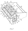
- the stapling machine has a frame comprising two side plates 10 joined by cross members 12.
- a transverse beam 14 secured between the side plates carries three inverted U-shaped brackets 16 in which are pivotally mounted the rear ends of three stapling heads 18.
- Spring wires 20 between the beam 14 and the stapling heads urge the stapling heads upwards.
- the movement of the stapling heads is restrained and controlled by a transverse rod 22 mounted between a pair of side arms 24 the rear ends of which are secured to a spindle 26 journalled to the side plates.
- the rod 22 bears upon the upwardly projecting plungers of the stapling heads so that they can be simultaneously pressed downwards by rotation of the spindle 26.
- a handle 28 mounted on a projecting end of the spindle 26 is used for manually effecting this rotation and hence the stapling action.
- the stapling heads co-operate with three anvils 32 which interrupt the top knife edge 34 of a plate 36 secured between the side plates 10 below the stapling heads.
- a pair of bars 38 are arranged below the stapling heads one on each side of the plane of the plate 36.
- the ends of the bars engage in horizontal slots 40 in slide plates 42 which are vertically slidable in tracks 44 mounted to the outside surfaces of the side plates 10.
- the bars are urged towards each other, and hence towards the mutually inner ends of the slots 40, by means of springs 46 connected between the ends of the bars.
- a pin 48 projecting from each slide plate 42 engages in a fork 50 in an arm 52 carried at a respective end of a spindle 54 journalled in the side plates 10.
- Fig. 1 the mechanisms on the outside surfaces of the side plates 10 are covered by shrouds 58.
- two platforms 60,62 are provided between the side plates 10, one on each side of the knife edge.
- One platform 60 which is the feed platform, is formed in two parts.
- a first part 60A is fixed relative to the framework, while a second part 60B adjacent the knife edge is hinged to the first part but is resiliently biased upwards by springs (not shown) so that it is normally horizontal and coplanar with the first part 60A.
- the other platform 62 is coplanar with the platform 60 (or at least with the fixed part 60A).
- Lateral sheet guides 64 are provided on the platform 60, and are laterally adjustable by movement along a rod 66 to which they can be clamped by means of hand screws 68.
- End stops 70 are carried at the ends of rods 72 projecting forwardly over the other platform 62 from the rear end thereof.
- the rods pass through blocks 74 mounted to the rear of the platform 62 and carrying hand screws 76 by which the rods can be clamped in a desired position.
- Fig. 1 also shows a pair of pivoted control arms 78,80.
- the arm 78 is secured to one of the slide plates 42 so that it moves up and down with it.
- the lower end of the arm bears upon the hinged platform portion 60B, so that as the slide plates 42 move downwards carrying the bars 38 into their depressed position, the platform part 60B is hinged downwards also.
- the arm 78 can be rotated to a horizontal position so that it does not engage the part 60B, thereby decoupling the platform part 60B from the bars 38 so that it remains horizontal when the bars are lowered.
- the arm 80 is normally inoperative, but it can be swung across when the bars 38 are in their depressed position so that its lower end bears upon the bars and holds them in the depressed position.
- sheet material 90 to be stapled along a spine is collated in the flat condition and laid on the platforms 60,62. It is introduced from the platform 60, and is located by the guides 64 whose positions are adjusted so that the sheet material will be in the correct position laterally with respect to the stapling heads.
- Three staples can be inserted simultaneously if desired, but in many cases only two staples will be required, in which case the stapling head which is not to be used has its staples removed, and the sheet material is positioned with respect to the other two stapling heads. Exceptionally, of course, only one staple may be inserted, in which case the staples are removed from two of the stapling heads.
- the sheet material is advanced over the platforms until its leading end encounters the end stops 70 which have been adjusted so that the intended spine lies directly over the plate 36.
- the stapling heads and bars 38 are in the raised position at this time, so the sheet material is introduced under the bars.
- the handle 56 is depressed, forcing the bars 38 downwards over the sheet material, as can be seen in Fig. 4, thereby creasing the sheet material over knife edge.
- Fig. 4 also shows how the lowering of the platform part 60B relieves the support on the sheet material adjacent the knife edge.
- the handle 28 is also depressed, bringing the stapling heads down onto the sheet material, as shown in Fig.
- Fig. 5 shows how edge stapling of sheet material can be effected without creasing.
- the arm 78 is first moved into the horizontal position, and then the handle 56 is depressed, bringing the bars 38 downwards on either side of the plate 36, but without lowering the platform portion 60B. The bars are then retained in this depressed position by moving across the arm 80 to engage them. Thereafter, collated sheet material can be laid upon the platform 60 so that an edge portion overlies the strip 36, and the handle 28 is operated to bring the stapling heads down and apply staples to the edge portion of the collated sheets.
- the end stops 70 can be advanced much closer to the strip 36 so as still to provide an end location for the collated sheets prior to stapling.
- stapling machine is in many respects similar to the first embodiment, and like parts have the same reference numerals.
- rotation of the spindle 26 is effected by means of a solenoid 27 acting through a push rod 29 connected to a crank arm 31 which is fast with the spindle 26.
- the ends of the folding bars 38 are carried on a pair of side arms 39 which are fast with a spindle 41 journalled to the side plates of the frame, at least one of the side arms 39 having an extension 43 which provides a handle for manually pivoting the arms.
- the ends of the bars 38 are loosely located in brackets 43 secured to the arms 39; each bracket having a central depending limb 45 which spaces the bars apart.
- the bars are urged towards each other by means of an encircling helical coil spring loop 47.
- a pad 53 of rubber or the like frictional material Between each bracket 43 and its respective arm 39 is located a pad 53 of rubber or the like frictional material.
- the bars are normally pressed against the pads 53 by means of helical springs 49 acting between the respective spring loops 47 and fixed points 51 on the arms. The overall effect of this is that friction between the cylindrical bars 38 and the pads 53 resists rotation of the bars.
- the bars 38 are provided with sleeves 55 of rubber or other non-slip material.
- the arms 39 are normally held in a raised condition in which the bars 38 are above the knife edge 34.
- downward pressure on the handle 43 brings the arms into a lowered condition, as shown in Fig. 6, the bars 38 passing downwardly on either side of the plate 36.
- they rest initially on a rubber buffer 82.
- further downward pressure on the handle 43 depresses the arms 39 further against the resilience of the buffer so that one of the arms contacts a microswitch 84 which actuates the solenoid 27.
- An end stop for the sheet material to be stapled is provided by a transverse member 69 at one end of a rectangular shaped bar 71 projecting forwardly over the other platform 62 from the rear end thereof.
- the bar is laterally grooved at 73 so as to engage in a slot extending forwardly in the plate 62 so that the position of the bar can be adjusted by sliding it along the slot. They can be clamped in the desired position by means of a hand screw 75 which tightens a transverse clamping bar 77 against the underside of the bar 71.
- the rearward plate part 60B is urged downwardly from its horizontal position under the action of a spring 79 and can be moved upwards to the horizontal position by cams (not shown) carried on the spindle 41, so that the plate moves downwardly with the arms 39.
- the plate part 60B can be held in its horizontal position during movement of the arms 39 by rotation of a spindle 81 which carries an arm 83 the upper end 85 of which can be brought into engagement with the underside of the plate part 60B as shown in Fig. 10.
- a pair of wedge-shaped cam plates 57 can be provided on each side plate 10 so that at the limit of the upward movement of the arms 39 an apex of each of the cam plates 57 enters between the bars 38, forcing them apart slightly and releasing their grip on the sheet material 90. The sheet material can then be readily withdrawn from between the bars, for example through a slot 87 in a shroud 89 (see Figs. 6 and 10).
- Fig. 11 shows an alternative arrangement for mounting the ends of the bars 38 to the arms 39. It still uses brackets 43 and rubber pads 53. However, in this case the helical springs are replaced by W-shaped wire springs 59 secured at 63 to their respective arms 39, the upward ends of the wire springs engaging in annular rebates in the ends of the bars 38 and pressing the bars towards each other.
- end caps 65 may be provided on the arms 39 to retain the bars lengthwise and prevent their accidental axial displacement.
- Fig. 12 shows a further modification of the arrangement of Fig. 7 in which the ends of the bars 38 are knurled 95, the knurling being engaged by spring plates 96 mounted on the arms 39 so as to provide a unidirectional ratchet which prevents the bars 38 from rotating during the upward movement of the arms 39, but allows them to rotate when the bars 38 rise to lift the knurling off the plates 96.
- the machine can also be used for stapling sheets without creasing.
- the platform portion 60B is kept in the raised position by rotation of the spindle 81.
- the arms 39 are lowered before the sheet material 90 is placed on the platforms so that the bars 38 are below the knife edge and resting on the rubber buffer 82, and a stop (see arm 80 in Fig. 1) is moved into position to prevent upward return of the arms 39 but not their further downward movement.
- Completion of the downward movement of the arms 39 against the buffer 82 activates the solenoid through the microswitch 84 to staple the sheets.
- the stop bar 71 can be moved forward until its end member 69 is just short of the plate 36, so that the staples are inserted in an edge region of the sheet material.
- FIG. 13 shows a modification which assists edge stapling.
- a special stop is provided by the actuating element 86 of a microswitch 88 carried at one end of an arm 91, the other end of which is journalled in a housing 92 mounted on the beam 14.
- the arm 91 is kept in a raised position by a spring loaded bolt 93.
- the bolt is drawn back, as shown in Fig. 13, the arm falls so that the element 86 is presented as the end stop for the paper in edge stapling.
- the microswitch 88 operates the solenoid 27 to actuate the stapling heads.
- a screw 94 moves the microswitch, and hence the element 86, a small amount so that the precise positioning of the staples from the edge of the sheet material can be adjusted.
- the end of the bolt abuts the side of the arm 91 as shown, so that simple upward pressure on the arm 91 or the microswitch end of it can raise the arm allowing the bolt to spring forward to prevent its falling once more.
Landscapes
- Engineering & Computer Science (AREA)
- Textile Engineering (AREA)
- Folding Of Thin Sheet-Like Materials, Special Discharging Devices, And Others (AREA)
Applications Claiming Priority (2)
| Application Number | Priority Date | Filing Date | Title |
|---|---|---|---|
| GB8126728 | 1981-09-03 | ||
| GB8126728 | 1981-09-03 |
Publications (2)
| Publication Number | Publication Date |
|---|---|
| EP0075404A2 true EP0075404A2 (fr) | 1983-03-30 |
| EP0075404A3 EP0075404A3 (fr) | 1985-02-06 |
Family
ID=10524301
Family Applications (1)
| Application Number | Title | Priority Date | Filing Date |
|---|---|---|---|
| EP82304613A Withdrawn EP0075404A3 (fr) | 1981-09-03 | 1982-09-02 | Agrafeuse |
Country Status (2)
| Country | Link |
|---|---|
| EP (1) | EP0075404A3 (fr) |
| GB (1) | GB2105241B (fr) |
Families Citing this family (1)
| Publication number | Priority date | Publication date | Assignee | Title |
|---|---|---|---|---|
| JP6694194B1 (ja) * | 2019-11-07 | 2020-05-13 | ホリゾン・インターナショナル株式会社 | 用紙束供給装置 |
Family Cites Families (2)
| Publication number | Priority date | Publication date | Assignee | Title |
|---|---|---|---|---|
| DE2162453A1 (de) * | 1971-12-16 | 1973-06-20 | Will E C H Fa | Verfahren und vorrichtung zur herstellung von heften |
| DE2242576C2 (de) * | 1972-08-30 | 1982-12-30 | E.C.H. Will (Gmbh & Co), 2000 Hamburg | Verfahren und Vorrichtung zum Falten mehrerer übereinanderliegender, klammergehefteter Papierbogen |
-
1982
- 1982-09-02 GB GB08225079A patent/GB2105241B/en not_active Expired
- 1982-09-02 EP EP82304613A patent/EP0075404A3/fr not_active Withdrawn
Also Published As
| Publication number | Publication date |
|---|---|
| GB2105241B (en) | 1984-08-22 |
| GB2105241A (en) | 1983-03-23 |
| EP0075404A3 (fr) | 1985-02-06 |
Similar Documents
| Publication | Publication Date | Title |
|---|---|---|
| EP0051395A2 (fr) | Dispositif de repliage et appareil à agrafer muni d'un tel dispositif | |
| US4410170A (en) | Machine for stapling and folding a stack of paper sheets to form a book | |
| US3451082A (en) | Method and apparatus for properly positioning a book within a case | |
| JPS6026680B2 (ja) | 未装本裁断機 | |
| US4466227A (en) | Machine for wrapping tape about an article | |
| US4754676A (en) | Computer paper guide edge shearer | |
| US4907942A (en) | Arrangement for separating paper sheet pads from a stack | |
| DE2721510B2 (de) | Automatische Nähmaschine | |
| JPH0437751Y2 (fr) | ||
| EP0075404A2 (fr) | Agrafeuse | |
| US2638986A (en) | Portable punching machine | |
| US5020786A (en) | Paper inserting apparatus | |
| US4403770A (en) | Apparatus for collating signatures | |
| US3190516A (en) | Multiple office form bursting apparatus | |
| CN210558180U (zh) | 一种分纸机构 | |
| JPH0813584B2 (ja) | 複数の枚葉紙束をステープル止めする方法及びステープラー装置 | |
| EP0644818A1 (fr) | Procede et appareil pour decouper des onglets | |
| US3883063A (en) | Punching and stapling apparatus | |
| US1870424A (en) | Automatic label printing, cutting, folding, and packing machine | |
| US3605535A (en) | Combined punching and cornering apparatus and method | |
| GB2175251A (en) | Book binding machine | |
| JP7022403B2 (ja) | ステープル除去装置 | |
| JPH028807B2 (fr) | ||
| JPS633768Y2 (fr) | ||
| JPH0541537B2 (fr) |
Legal Events
| Date | Code | Title | Description |
|---|---|---|---|
| PUAI | Public reference made under article 153(3) epc to a published international application that has entered the european phase |
Free format text: ORIGINAL CODE: 0009012 |
|
| AK | Designated contracting states |
Designated state(s): DE FR IT NL SE |
|
| PUAL | Search report despatched |
Free format text: ORIGINAL CODE: 0009013 |
|
| AK | Designated contracting states |
Designated state(s): DE FR IT NL SE |
|
| STAA | Information on the status of an ep patent application or granted ep patent |
Free format text: STATUS: THE APPLICATION IS DEEMED TO BE WITHDRAWN |
|
| 18D | Application deemed to be withdrawn |
Effective date: 19851008 |
|
| RIN1 | Information on inventor provided before grant (corrected) |
Inventor name: SMITH, KENNETH MALCOLM |