EP0075408A2 - Drehkraftgetriebe - Google Patents
Drehkraftgetriebe Download PDFInfo
- Publication number
- EP0075408A2 EP0075408A2 EP82304693A EP82304693A EP0075408A2 EP 0075408 A2 EP0075408 A2 EP 0075408A2 EP 82304693 A EP82304693 A EP 82304693A EP 82304693 A EP82304693 A EP 82304693A EP 0075408 A2 EP0075408 A2 EP 0075408A2
- Authority
- EP
- European Patent Office
- Prior art keywords
- drive
- gear
- clutch
- layshafts
- rotary transmission
- Prior art date
- Legal status (The legal status is an assumption and is not a legal conclusion. Google has not performed a legal analysis and makes no representation as to the accuracy of the status listed.)
- Granted
Links
- 230000005540 biological transmission Effects 0.000 title claims abstract description 37
- 230000000712 assembly Effects 0.000 description 6
- 238000000429 assembly Methods 0.000 description 6
- 239000012530 fluid Substances 0.000 description 4
- 238000004519 manufacturing process Methods 0.000 description 3
- 230000008878 coupling Effects 0.000 description 2
- 238000010168 coupling process Methods 0.000 description 2
- 238000005859 coupling reaction Methods 0.000 description 2
- 230000009977 dual effect Effects 0.000 description 2
- 230000000694 effects Effects 0.000 description 2
- 238000009434 installation Methods 0.000 description 2
- 230000007246 mechanism Effects 0.000 description 2
- 239000000446 fuel Substances 0.000 description 1
- 239000000463 material Substances 0.000 description 1
- 239000000725 suspension Substances 0.000 description 1
Images

Classifications
-
- F—MECHANICAL ENGINEERING; LIGHTING; HEATING; WEAPONS; BLASTING
- F16—ENGINEERING ELEMENTS AND UNITS; GENERAL MEASURES FOR PRODUCING AND MAINTAINING EFFECTIVE FUNCTIONING OF MACHINES OR INSTALLATIONS; THERMAL INSULATION IN GENERAL
- F16H—GEARING
- F16H3/00—Toothed gearings for conveying rotary motion with variable gear ratio or for reversing rotary motion
- F16H3/02—Toothed gearings for conveying rotary motion with variable gear ratio or for reversing rotary motion without gears having orbital motion
- F16H3/08—Toothed gearings for conveying rotary motion with variable gear ratio or for reversing rotary motion without gears having orbital motion exclusively or essentially with continuously meshing gears, that can be disengaged from their shafts
- F16H3/087—Toothed gearings for conveying rotary motion with variable gear ratio or for reversing rotary motion without gears having orbital motion exclusively or essentially with continuously meshing gears, that can be disengaged from their shafts characterised by the disposition of the gears
- F16H3/093—Toothed gearings for conveying rotary motion with variable gear ratio or for reversing rotary motion without gears having orbital motion exclusively or essentially with continuously meshing gears, that can be disengaged from their shafts characterised by the disposition of the gears with two or more countershafts
-
- F—MECHANICAL ENGINEERING; LIGHTING; HEATING; WEAPONS; BLASTING
- F16—ENGINEERING ELEMENTS AND UNITS; GENERAL MEASURES FOR PRODUCING AND MAINTAINING EFFECTIVE FUNCTIONING OF MACHINES OR INSTALLATIONS; THERMAL INSULATION IN GENERAL
- F16H—GEARING
- F16H3/00—Toothed gearings for conveying rotary motion with variable gear ratio or for reversing rotary motion
- F16H3/02—Toothed gearings for conveying rotary motion with variable gear ratio or for reversing rotary motion without gears having orbital motion
- F16H3/08—Toothed gearings for conveying rotary motion with variable gear ratio or for reversing rotary motion without gears having orbital motion exclusively or essentially with continuously meshing gears, that can be disengaged from their shafts
- F16H3/087—Toothed gearings for conveying rotary motion with variable gear ratio or for reversing rotary motion without gears having orbital motion exclusively or essentially with continuously meshing gears, that can be disengaged from their shafts characterised by the disposition of the gears
- F16H3/093—Toothed gearings for conveying rotary motion with variable gear ratio or for reversing rotary motion without gears having orbital motion exclusively or essentially with continuously meshing gears, that can be disengaged from their shafts characterised by the disposition of the gears with two or more countershafts
- F16H2003/0931—Toothed gearings for conveying rotary motion with variable gear ratio or for reversing rotary motion without gears having orbital motion exclusively or essentially with continuously meshing gears, that can be disengaged from their shafts characterised by the disposition of the gears with two or more countershafts each countershaft having an output gear meshing with a single common gear on the output shaft
-
- F—MECHANICAL ENGINEERING; LIGHTING; HEATING; WEAPONS; BLASTING
- F16—ENGINEERING ELEMENTS AND UNITS; GENERAL MEASURES FOR PRODUCING AND MAINTAINING EFFECTIVE FUNCTIONING OF MACHINES OR INSTALLATIONS; THERMAL INSULATION IN GENERAL
- F16H—GEARING
- F16H2200/00—Transmissions for multiple ratios
- F16H2200/003—Transmissions for multiple ratios characterised by the number of forward speeds
- F16H2200/0052—Transmissions for multiple ratios characterised by the number of forward speeds the gear ratios comprising six forward speeds
-
- F—MECHANICAL ENGINEERING; LIGHTING; HEATING; WEAPONS; BLASTING
- F16—ENGINEERING ELEMENTS AND UNITS; GENERAL MEASURES FOR PRODUCING AND MAINTAINING EFFECTIVE FUNCTIONING OF MACHINES OR INSTALLATIONS; THERMAL INSULATION IN GENERAL
- F16H—GEARING
- F16H3/00—Toothed gearings for conveying rotary motion with variable gear ratio or for reversing rotary motion
- F16H3/006—Toothed gearings for conveying rotary motion with variable gear ratio or for reversing rotary motion power being selectively transmitted by parallel flow paths, e.g. dual clutch transmissions
-
- Y—GENERAL TAGGING OF NEW TECHNOLOGICAL DEVELOPMENTS; GENERAL TAGGING OF CROSS-SECTIONAL TECHNOLOGIES SPANNING OVER SEVERAL SECTIONS OF THE IPC; TECHNICAL SUBJECTS COVERED BY FORMER USPC CROSS-REFERENCE ART COLLECTIONS [XRACs] AND DIGESTS
- Y10—TECHNICAL SUBJECTS COVERED BY FORMER USPC
- Y10T—TECHNICAL SUBJECTS COVERED BY FORMER US CLASSIFICATION
- Y10T74/00—Machine element or mechanism
- Y10T74/19—Gearing
- Y10T74/19219—Interchangeably locked
- Y10T74/19223—Disconnectable counter shaft
-
- Y—GENERAL TAGGING OF NEW TECHNOLOGICAL DEVELOPMENTS; GENERAL TAGGING OF CROSS-SECTIONAL TECHNOLOGIES SPANNING OVER SEVERAL SECTIONS OF THE IPC; TECHNICAL SUBJECTS COVERED BY FORMER USPC CROSS-REFERENCE ART COLLECTIONS [XRACs] AND DIGESTS
- Y10—TECHNICAL SUBJECTS COVERED BY FORMER USPC
- Y10T—TECHNICAL SUBJECTS COVERED BY FORMER US CLASSIFICATION
- Y10T74/00—Machine element or mechanism
- Y10T74/19—Gearing
- Y10T74/19219—Interchangeably locked
- Y10T74/19233—Plurality of counter shafts
-
- Y—GENERAL TAGGING OF NEW TECHNOLOGICAL DEVELOPMENTS; GENERAL TAGGING OF CROSS-SECTIONAL TECHNOLOGIES SPANNING OVER SEVERAL SECTIONS OF THE IPC; TECHNICAL SUBJECTS COVERED BY FORMER USPC CROSS-REFERENCE ART COLLECTIONS [XRACs] AND DIGESTS
- Y10—TECHNICAL SUBJECTS COVERED BY FORMER USPC
- Y10T—TECHNICAL SUBJECTS COVERED BY FORMER US CLASSIFICATION
- Y10T74/00—Machine element or mechanism
- Y10T74/19—Gearing
- Y10T74/19219—Interchangeably locked
- Y10T74/19242—Combined gear and clutch
-
- Y—GENERAL TAGGING OF NEW TECHNOLOGICAL DEVELOPMENTS; GENERAL TAGGING OF CROSS-SECTIONAL TECHNOLOGIES SPANNING OVER SEVERAL SECTIONS OF THE IPC; TECHNICAL SUBJECTS COVERED BY FORMER USPC CROSS-REFERENCE ART COLLECTIONS [XRACs] AND DIGESTS
- Y10—TECHNICAL SUBJECTS COVERED BY FORMER USPC
- Y10T—TECHNICAL SUBJECTS COVERED BY FORMER US CLASSIFICATION
- Y10T74/00—Machine element or mechanism
- Y10T74/19—Gearing
- Y10T74/19219—Interchangeably locked
- Y10T74/19377—Slidable keys or clutches
- Y10T74/19386—Multiple clutch shafts
- Y10T74/19391—Progressive
- Y10T74/19395—Keys simultaneously slidable
Definitions
- This invention relates to rotary transmissions of the dual clutch kind by which is meant a transmission having gear trains each being one of a set providing a series of increasing speed ratios, and two clutches independently operable and providing alternative drive paths through the gear trains between a common input and a common output, the gear trains of alternate ratios in the set being driven respectively through one and the other clutch.
- the invention is particularly though not exclusively applicable to drive transmissions for motor vehicles.
- Front wheel drive vehicles usually have the engine, clutch, gearbox and final drive mechanisms assembled as a single power unit; this can reduce material and manufacturing costs.
- Small transverse engined vehicles have little space between the front wheel suspension mechanisms to site the power unit. It has been proposed to place the gearbox beneath the engine but this leads to low ground clearance and/or a high bonnet line with consequent reduced driver visibility. Although small transverse engined vehicles having gearboxes placed alongside the engine are known it is uncommon to find such vehicles fitted with a fully atuomatic transmission.
- the present invention seeks to provide a constant mesh rotary transmission which is suitable for small transverse engined vehicles, which provides a greater number of speed ratios than is usual for such transmissions and which is suitable for adaption to fully automatic control.
- a rotary transmission having between an input and an output a set of gear trains each providing one of a series of increasing speed ratios and two independently operable clutches, sequential gear trains in the series being arranged respectively for drive through one and the other clutch, the gear trains being arranged only for drive from an input shaft to one of two parallel layshafts, the layshafts being for continuous direct drive to the output characterised thereby that a transfer gear train is additionally provided for drive between the layshafts, means being provided to disconnect one of said layshafts from continuous direct drive to the output.
- Such an arrangement can provide six well- spaced forward speed ratios from a very compact gear set.
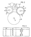
- Fig. 1 For ease of understanding the transmission is depicted in Fig. 1 as having the three main shafts all lying in the same plane. As will be apparent from the following text and as shown in Fig. 2 one of the shafts may advantageously be out of the plane of the remaining two.
- the torque input to the transmission may be direct from an engine or may be through a fluid coupling, for example a hydrodynamic torque converter.
- the coupling may include a lock-up clutch engageable to directly connect its input and output.
- the transmission is intended for fully automatic operation as is described hereinafter.
- FIGs. 1 and 2 there is shown an input shaft 11 from an engine and connectable through either a clutch 12 or clutch 13 and trains of gear wheels with output shafts 14 and 15 having respective output gear wheels 16 and 17.
- the gear wheels 16 and 17 are in mesh with a gear wheel 18 of an output shaft 19 which may part of a differential gear assembly for transmission of driving torque to vehicle wheels.
- the wheel 16 is journalled on the shaft 14 whilst the wheel 17 is fast for rotation with its shaft 15.
- Clutch 12 is preferably a conventional single dry plate clutch having the usual flywheel 21, driven plate 22, pressure plate 23, clutch cover 24 and spring 25.
- a release bearing 26 is operable to relieve the spring load and thus release the driven plate 22.
- a drive shaft 27, fast for rotation with the flywheel 21, extends through the set of gear trains to the opposite side of the transmissions to drive the other clutch.
- Clutch 13 is a wet plate clutch having a drive member 31, pressure plate 32 and driven plate 33.
- a piston 34, housed in the drive member 31 is supplied with fluid under pressure via a duct 35 in a transmission end cover 36.
- a pressure relief valve 37 whose function is explained subsequently, is housed in the piston 34.
- an input gear wheel, respectively 41 and 42 is journalled on the drive shaft 27.
- Each gear wheel 41,42 drives two gear wheels respectively 43,44 and 45,46 journalled on the output shafts 14,15.
- a transfer gear train between the output shafts comprises a gear wheel 47 journalled on shaft 15, an idler wheel 48 journalled on the drive shaft 27 intermediate the input gears 41,42, and a wheel 49 fast for rotation with the shaft 14.
- the idler wheel 48 has a respective gear profile for engagement with each of the wheels 47,49 in order to provide an even spread of transmission ratios.
- a synchroniser and dog clutch assembly S1 is provided to connect output wheel 16 for rotation with shaft 14. Further assemblies S2-S6 are operable to connect the gear wheels 43-47 with the shafts on which they are journalled.
- Such synchroniser assemblies are of a type found in manual change transmissions and are well understood in the rotary change speed transmission art.
- a reverse speed ratio is provided between a gear profile of the idler gear wheel 48, a disengageable idler wheel 51 and a gear profile 52 formed on the double synchroniser assembly S2.S4.
- a drive gear wheel 53, for a hydraulic pump 54, is fast for rotation with the drive shaft 27 adjacent the idler wheel 48.
- the pump provides fluid under pressure for transmission operation, for example engagement of the clutch 13.
- a parklock wheel 55 is splined to the output shaft 15 and is engageable with a pawl (not shown) to provide a mechanical lock for the transmission.
- a lock is a usual provision for vehicles fitted with fully automatic transmissions.
- Gear wheel 16 is driven by differential gear 18 at all times but is free to turn relative to output shaft 14 by virtue of being journalled thereon.
- Second speed may be pre-selected by engagement of synchroniser assembly S6, thus driven plate 33 of clutch 13 is driven idly by output shaft 14 through gear train 46,42.
- Synchroniser assembly S5 may remain engaged in anticipation of a ratio change back into 1st speed or may be disengaged in preparation for a change to third ratio.
- Third speed ratio may be preselected by engagement of synchroniser assembly S3 to idly drive driven plate 22 through gear train 43,41.
- a speed ratio change from 2nd to 3rd is effected in the manner of the previous ratio change, by simultaneously disengaging clutch 13 and engaging clutch 12, synchroniser assemblies S6 and S2 then being disengaged in preparation for a further upchange if desired.
- the ratio change to 6th speed is effected as previously described after preselection engagement of synchroniser assembly S6.
- the relief valve 37 is to prevent a build up of fluid pressure behind the piston 34 due to centrifugal forces.
- the dimensions of the ball and valve bore are carefully chosen to ensure that supply of pressure through duct 35 will force the ball into its seat to close the valve. Release of clutch engaging pressure allows the ball to roll up its seat under centrifugal load to open the valve.
- gear wheel 16 is fast for rotation with output shaft 14 whilst synchroniser assemblies S5 and S6 and gear wheels 44 and 49 are mounted on an annular shaft journalled on the output shaft 14. Synchroniser assembly S1 then connects output shaft 14 to the annular shaft. Operation of the transmission is unchanged but the alternative arrangement may be more suitable under different installation conditions.
Landscapes
- Engineering & Computer Science (AREA)
- General Engineering & Computer Science (AREA)
- Mechanical Engineering (AREA)
- Structure Of Transmissions (AREA)
Applications Claiming Priority (2)
| Application Number | Priority Date | Filing Date | Title |
|---|---|---|---|
| GB8128374 | 1981-09-19 | ||
| GB8128374 | 1981-09-19 |
Publications (3)
| Publication Number | Publication Date |
|---|---|
| EP0075408A2 true EP0075408A2 (de) | 1983-03-30 |
| EP0075408A3 EP0075408A3 (en) | 1984-10-17 |
| EP0075408B1 EP0075408B1 (de) | 1987-02-25 |
Family
ID=10524621
Family Applications (1)
| Application Number | Title | Priority Date | Filing Date |
|---|---|---|---|
| EP82304693A Expired EP0075408B1 (de) | 1981-09-19 | 1982-09-08 | Drehkraftgetriebe |
Country Status (9)
| Country | Link |
|---|---|
| US (1) | US4476737A (de) |
| EP (1) | EP0075408B1 (de) |
| JP (1) | JPS5865350A (de) |
| AU (1) | AU552791B2 (de) |
| BR (1) | BR8205449A (de) |
| DE (1) | DE3275478D1 (de) |
| ES (1) | ES8308012A1 (de) |
| GB (1) | GB2107805B (de) |
| SU (1) | SU1189330A3 (de) |
Cited By (6)
| Publication number | Priority date | Publication date | Assignee | Title |
|---|---|---|---|---|
| EP0164857A3 (de) * | 1984-05-10 | 1987-03-11 | Automotive Products Public Limited Company | Getriebe |
| EP1865226A1 (de) * | 2006-05-30 | 2007-12-12 | Mitsubishi Jidosha Kogyo Kabushiki Kaisha | Doppelkupplungsgetriebe |
| CN101871510A (zh) * | 2009-04-23 | 2010-10-27 | 通用汽车环球科技运作公司 | 双离合变速器 |
| FR2956175A1 (fr) * | 2010-02-05 | 2011-08-12 | Renault Sas | Boite de vitesses automatisee a deux embrayages disjoints |
| US8161836B2 (en) | 2008-03-26 | 2012-04-24 | Zf Friedrichshafen Ag | Multi-step transmission |
| US8555738B2 (en) * | 2008-03-26 | 2013-10-15 | Zf Friedrichshafen Ag | Device for reducing rattling noises in variable-speed transmissions |
Families Citing this family (24)
| Publication number | Priority date | Publication date | Assignee | Title |
|---|---|---|---|---|
| USRE33336E (en) * | 1984-03-16 | 1990-09-18 | Automotive Products Plc | Change speed transmission |
| GB8406969D0 (en) * | 1984-03-16 | 1984-04-18 | Automotive Prod Plc | Change speed transmission |
| GB2159216B (en) * | 1984-05-25 | 1988-08-10 | Automotive Products Plc | Transmission control system |
| US4597304A (en) * | 1984-10-09 | 1986-07-01 | General Motors Corporation | Multi-speed power transmission |
| US4676115A (en) * | 1985-05-13 | 1987-06-30 | Eaton Corporation | Semi-automatic transmission |
| DE3530017A1 (de) * | 1985-08-22 | 1987-02-26 | Porsche Ag | Gangschaltgetriebe fuer ein kraftfahrzeug |
| FR2605377B2 (fr) * | 1985-10-25 | 1993-11-26 | Renault | Boite de vitesses mecanique a un arbre primaire et a deux arbres secondaires |
| DE3543269A1 (de) * | 1985-12-06 | 1987-06-11 | Voith Gmbh J M | Stufenschaltgetriebe |
| JPS6455452A (en) * | 1987-08-21 | 1989-03-02 | Toyota Motor Corp | Manual transmission for vehicle |
| JPH01303340A (ja) * | 1988-05-31 | 1989-12-07 | Fuji Heavy Ind Ltd | 縦置式エンジンにおける自動変速機 |
| US5009118A (en) * | 1990-03-30 | 1991-04-23 | General Motors Corporation | Power transmission with parallel identical countershafts |
| US5385064A (en) * | 1992-10-23 | 1995-01-31 | Borg-Warner Automotive, Inc. | Dual clutch countershaft automatic transmission |
| US5390560A (en) * | 1993-02-09 | 1995-02-21 | General Motors Corporation | Countershafts power transmission |
| DE60011537T2 (de) * | 1999-04-23 | 2005-08-25 | Yanmar Diesel Engine Co., Ltd. | Anordnung eines fahrzeugantriebssystems |
| JP2002130396A (ja) * | 2000-10-30 | 2002-05-09 | Aisin Seiki Co Ltd | 変速装置 |
| KR100569141B1 (ko) * | 2003-12-10 | 2006-04-07 | 현대자동차주식회사 | 이중 클러치 변속기 |
| DE102004056936B4 (de) * | 2004-11-23 | 2011-02-03 | Getrag Getriebe- Und Zahnradfabrik Hermann Hagenmeyer Gmbh & Cie Kg | Stufenwechselgetriebe für ein Kraftfahrzeug |
| FR2882417B1 (fr) * | 2005-02-24 | 2008-08-29 | Renault Sas | Montage de roulements sur des arbres concentriques |
| FR2885980B1 (fr) * | 2005-05-18 | 2007-08-10 | Renault Sas | Boite de vitesse avec pompe a huile laterale |
| US8528431B2 (en) * | 2009-04-28 | 2013-09-10 | GM Global Technology Operations LLC | Dual clutch transmission |
| GB2478351B (en) * | 2010-03-05 | 2016-09-07 | Gm Global Tech Operations Llc | Transmission for vehicles |
| RU2691506C1 (ru) * | 2018-10-30 | 2019-06-14 | федеральное государственное автономное образовательное учреждение высшего образования "Санкт-Петербургский политехнический университет Петра Великого" (ФГАОУ ВО "СПбПУ") | 24-режимная однопоточная вальная коробка передач "Конфигурация-24" |
| DE102020134114A1 (de) * | 2020-12-18 | 2022-06-23 | Deere & Company | Getriebe und landwirtschaftliches oder industrielles Nutzfahrzeug |
| US12215765B2 (en) * | 2022-08-24 | 2025-02-04 | Dana Belgium N.V. | Layout scheme 1X1 powershift transmission with output speed reducing ratio |
Family Cites Families (18)
| Publication number | Priority date | Publication date | Assignee | Title |
|---|---|---|---|---|
| GB594408A (en) * | 1944-09-30 | 1947-11-11 | Howard Frederick Hobbs | Improvements in or relating to power transmission mechanism |
| DE153993C (de) * | ||||
| US1759558A (en) * | 1928-04-04 | 1930-05-20 | Krupp Ag | Variable-speed gear |
| US2543412A (en) * | 1942-08-07 | 1951-02-27 | Kegresse Adolphe Valentin | Change-speed transmission |
| US2466318A (en) * | 1945-08-22 | 1949-04-05 | Ford Motor Co | Automatic transmission and overdrive |
| US2599801A (en) * | 1949-06-11 | 1952-06-10 | Borg Warner | Double countershaft transmission |
| US2612787A (en) * | 1950-07-22 | 1952-10-07 | Borg Warner | Double countershaft transmission |
| GB717450A (en) * | 1951-09-01 | 1954-10-27 | Dietrich & Cie De | Improvements in change-speed mechanism |
| GB795260A (en) * | 1955-09-29 | 1958-05-21 | Brown David & Sons Ltd | An improvement in or relating to variable-speed gearboxes |
| DE1530994B2 (de) * | 1967-03-03 | 1974-07-25 | Robert Bosch Gmbh, 7000 Stuttgart | Stirnradschaltgetriebe mit vier Vorwärtsgängen, insbesondere für Kraftfahrzeuge |
| DE2445241C2 (de) * | 1974-09-21 | 1982-11-04 | Fichtel & Sachs Ag, 8720 Schweinfurt | Schaltgetriebe für Kraftfahrzeuge |
| US4033200A (en) * | 1975-04-24 | 1977-07-05 | Ford Motor Company | Five speed overdrive transmission |
| FR2396213A1 (fr) * | 1977-06-30 | 1979-01-26 | Berliet Automobiles | Boite de vitesses compacte pour un vehicule automobile |
| SU680923A1 (ru) * | 1977-12-08 | 1979-08-25 | Московский Трижды Ордена Ленина,Ордена Октябрьской Революции И Ордена Трудового Красного Знамени Автомобильный Завод Им.А.И.Лихачева(Производственное Объединение Зил) | Трехступенчата коробка передач транспортного средства |
| JPS54153957A (en) * | 1978-05-26 | 1979-12-04 | Daikin Mfg Co Ltd | Transmission |
| JPS54153958A (en) * | 1978-05-26 | 1979-12-04 | Daikin Mfg Co Ltd | Transmission |
| AU6430980A (en) * | 1979-11-26 | 1981-06-04 | Automotive Products Ltd. | Dual clutch transmission |
| EP0060624A3 (de) * | 1981-03-10 | 1983-09-14 | Automotive Products Public Limited Company | Getriebe zur Übertragung einer Drehbewegung |
-
1982
- 1982-08-27 AU AU87791/82A patent/AU552791B2/en not_active Ceased
- 1982-09-08 DE DE8282304693T patent/DE3275478D1/de not_active Expired
- 1982-09-08 GB GB08225658A patent/GB2107805B/en not_active Expired
- 1982-09-08 EP EP82304693A patent/EP0075408B1/de not_active Expired
- 1982-09-13 US US06/417,503 patent/US4476737A/en not_active Expired - Fee Related
- 1982-09-16 BR BR8205449A patent/BR8205449A/pt unknown
- 1982-09-17 SU SU823493799A patent/SU1189330A3/ru active
- 1982-09-17 JP JP57162079A patent/JPS5865350A/ja active Pending
- 1982-09-17 ES ES515792A patent/ES8308012A1/es not_active Expired
Cited By (9)
| Publication number | Priority date | Publication date | Assignee | Title |
|---|---|---|---|---|
| EP0164857A3 (de) * | 1984-05-10 | 1987-03-11 | Automotive Products Public Limited Company | Getriebe |
| EP1865226A1 (de) * | 2006-05-30 | 2007-12-12 | Mitsubishi Jidosha Kogyo Kabushiki Kaisha | Doppelkupplungsgetriebe |
| KR100878975B1 (ko) | 2006-05-30 | 2009-01-19 | 미쯔비시 지도샤 고교 가부시끼가이샤 | 더블클러치 변속기 |
| US7735389B2 (en) | 2006-05-30 | 2010-06-15 | Mitsubishi Jidosha Kogyo Kabushiki Kaisha | Double clutch transmission |
| US8161836B2 (en) | 2008-03-26 | 2012-04-24 | Zf Friedrichshafen Ag | Multi-step transmission |
| US8555738B2 (en) * | 2008-03-26 | 2013-10-15 | Zf Friedrichshafen Ag | Device for reducing rattling noises in variable-speed transmissions |
| CN101871510A (zh) * | 2009-04-23 | 2010-10-27 | 通用汽车环球科技运作公司 | 双离合变速器 |
| CN101871510B (zh) * | 2009-04-23 | 2013-03-27 | 通用汽车环球科技运作公司 | 双离合变速器 |
| FR2956175A1 (fr) * | 2010-02-05 | 2011-08-12 | Renault Sas | Boite de vitesses automatisee a deux embrayages disjoints |
Also Published As
| Publication number | Publication date |
|---|---|
| EP0075408B1 (de) | 1987-02-25 |
| AU552791B2 (en) | 1986-06-19 |
| GB2107805B (en) | 1985-07-24 |
| JPS5865350A (ja) | 1983-04-19 |
| DE3275478D1 (en) | 1987-04-02 |
| GB2107805A (en) | 1983-05-05 |
| EP0075408A3 (en) | 1984-10-17 |
| ES515792A0 (es) | 1983-08-16 |
| SU1189330A3 (ru) | 1985-10-30 |
| BR8205449A (pt) | 1983-08-23 |
| ES8308012A1 (es) | 1983-08-16 |
| AU8779182A (en) | 1983-03-31 |
| US4476737A (en) | 1984-10-16 |
Similar Documents
| Publication | Publication Date | Title |
|---|---|---|
| US4476737A (en) | Rotary power transmission | |
| EP0046373A1 (de) | Getriebe zur Übertragung von Drehbewegungen | |
| US9068637B2 (en) | Powershift transmission in a motor vehicle | |
| US3906817A (en) | Multiple speed transmission | |
| EP2126411B2 (de) | Fahrzeuggetriebe mit mehrgang-doppelkupplung | |
| US5787756A (en) | Multispeed powershift reversing gear | |
| US4485687A (en) | Rotary transmission | |
| EP0061845A2 (de) | Getriebe zur Übertragung einer Drehbewegung | |
| GB2112088A (en) | A gear transmission mechanism with multiple layshafts | |
| EP0942198A1 (de) | Kraftübertragungssystem mit zwei einfachen Planetensätzen | |
| EP0061903B1 (de) | Getriebe zur Übertragung einer Drehbewegung | |
| GB2069635A (en) | Rotary transmission | |
| US5425283A (en) | Multi-speed power transmission | |
| US4627301A (en) | Change speed transmission | |
| US4063464A (en) | Agricultural tractor transmission | |
| US20040083837A1 (en) | Automated multiple-gear transmission | |
| US4693129A (en) | Countershaft automatic transmission | |
| US5333512A (en) | Multistage transmission with an automatic load-shift spur gear | |
| EP0139491A1 (de) | Mehrganggetriebe | |
| EP1091143A2 (de) | Mehrgängiges Getriebe mit einer mechanischen Kupplung | |
| USRE33336E (en) | Change speed transmission | |
| WO1992010380A1 (en) | Automatic transmission for motor vehicles | |
| EP0042677A1 (de) | Rotationsgetriebe | |
| EP0675299B1 (de) | Getriebe mit mehreren Vorgelegewellen | |
| CS226877B1 (en) | Self-changing differential gearbox |
Legal Events
| Date | Code | Title | Description |
|---|---|---|---|
| PUAI | Public reference made under article 153(3) epc to a published international application that has entered the european phase |
Free format text: ORIGINAL CODE: 0009012 |
|
| AK | Designated contracting states |
Designated state(s): AT BE DE FR GB IT NL SE |
|
| PUAL | Search report despatched |
Free format text: ORIGINAL CODE: 0009013 |
|
| AK | Designated contracting states |
Designated state(s): AT BE DE FR GB IT NL SE |
|
| 17P | Request for examination filed |
Effective date: 19841101 |
|
| 17Q | First examination report despatched |
Effective date: 19860120 |
|
| RBV | Designated contracting states (corrected) |
Designated state(s): DE FR IT SE |
|
| GRAA | (expected) grant |
Free format text: ORIGINAL CODE: 0009210 |
|
| AK | Designated contracting states |
Kind code of ref document: B1 Designated state(s): DE FR IT SE |
|
| PG25 | Lapsed in a contracting state [announced via postgrant information from national office to epo] |
Ref country code: IT Free format text: LAPSE BECAUSE OF FAILURE TO SUBMIT A TRANSLATION OF THE DESCRIPTION OR TO PAY THE FEE WITHIN THE PRESCRIBED TIME-LIMIT;WARNING: LAPSES OF ITALIAN PATENTS WITH EFFECTIVE DATE BEFORE 2007 MAY HAVE OCCURRED AT ANY TIME BEFORE 2007. THE CORRECT EFFECTIVE DATE MAY BE DIFFERENT FROM THE ONE RECORDED. Effective date: 19870225 |
|
| REF | Corresponds to: |
Ref document number: 3275478 Country of ref document: DE Date of ref document: 19870402 |
|
| ET | Fr: translation filed | ||
| PG25 | Lapsed in a contracting state [announced via postgrant information from national office to epo] |
Ref country code: SE Effective date: 19870909 |
|
| PLBE | No opposition filed within time limit |
Free format text: ORIGINAL CODE: 0009261 |
|
| STAA | Information on the status of an ep patent application or granted ep patent |
Free format text: STATUS: NO OPPOSITION FILED WITHIN TIME LIMIT |
|
| 26N | No opposition filed | ||
| PG25 | Lapsed in a contracting state [announced via postgrant information from national office to epo] |
Ref country code: DE Effective date: 19880601 |
|
| PGFP | Annual fee paid to national office [announced via postgrant information from national office to epo] |
Ref country code: FR Payment date: 19890807 Year of fee payment: 8 |
|
| ITTA | It: last paid annual fee | ||
| PG25 | Lapsed in a contracting state [announced via postgrant information from national office to epo] |
Ref country code: FR Effective date: 19910530 |
|
| REG | Reference to a national code |
Ref country code: FR Ref legal event code: ST |
|
| EUG | Se: european patent has lapsed |
Ref document number: 82304693.3 Effective date: 19880907 |