EP0075489A2 - Gruppierung von Artikeln in Übereinstimmung mit vorgewählten Anforderungen nach Zahl/Gewicht - Google Patents
Gruppierung von Artikeln in Übereinstimmung mit vorgewählten Anforderungen nach Zahl/Gewicht Download PDFInfo
- Publication number
- EP0075489A2 EP0075489A2 EP82305000A EP82305000A EP0075489A2 EP 0075489 A2 EP0075489 A2 EP 0075489A2 EP 82305000 A EP82305000 A EP 82305000A EP 82305000 A EP82305000 A EP 82305000A EP 0075489 A2 EP0075489 A2 EP 0075489A2
- Authority
- EP
- European Patent Office
- Prior art keywords
- weight
- combined
- articles
- numbers
- equal
- Prior art date
- Legal status (The legal status is an assumption and is not a legal conclusion. Google has not performed a legal analysis and makes no representation as to the accuracy of the status listed.)
- Granted
Links
Images


Classifications
-
- G—PHYSICS
- G01—MEASURING; TESTING
- G01G—WEIGHING
- G01G13/00—Weighing apparatus with automatic feed or discharge for weighing-out batches of material
-
- G—PHYSICS
- G01—MEASURING; TESTING
- G01G—WEIGHING
- G01G19/00—Weighing apparatus or methods adapted for special purposes not provided for in the preceding groups
- G01G19/40—Weighing apparatus or methods adapted for special purposes not provided for in the preceding groups with provisions for indicating, recording, or computing price or other quantities dependent on the weight
- G01G19/42—Weighing apparatus or methods adapted for special purposes not provided for in the preceding groups with provisions for indicating, recording, or computing price or other quantities dependent on the weight for counting by weighing
Definitions
- This invention relates to batching articles in accordance with preselected number/weight requirements.
- a combinatorial counting method for use in a case where the individual or unit weight of an article varies slightly from one article to the next, as in the case of nuts and bolts and small packaging cups for milk or other liquids, especially where the individual weight of supplied articles varies gradually with time. More particularly, it is desirable in such a combinatorial counting method to achieve a lengthening of the time period during which the total weight of articles discharged from a weighing system is substantially constant.
- a combinatorial counting apparatus operates by weighing articles through use of a plurality of weighing machines supplied with the articles, converting the weight value measured by each weighing machine into the number of articles supplied to that machine, and computing combinations of the article numbers provided by each weighing machine to obtain a set number of the articles.
- the weight-to-number conversion is performed by dividing the weight measured by each weighing machine by the individual weight (namely the weight per article, referred to as the "unit" weight hereinafter) of the articles contained in that weighing machine.
- the number of articles computed to be contained in each weighing machine may be subject to error, with the result that the combined number of articles computed by combinatorially adding the articles in each of the weighing machines is also subjected to an error.
- the articles therefore may not be counted accurately.
- Another problem is that the greater the number of articles to be counted by a single weighing machine, the greater may be the error in the computed number of articles.
- it is required to first obtain a correct measure of the unit weight of each article. While this may be acceptable where the unit weights are constant, however, in actual practice the units weights are not constant because some articles are inevitably lighter or heavier than others.
- a counting method which includes the steps of weighing a multiplicity of articles with a number n weighing machines, dividing the total weight measured by each weighing machine by the unit weight of the article to find the number of articles contained in each of the weighing machines, computing various combinations of numbers of articles to determine the number of articles thus combined, and finding one of the combinations having the number of articles equal or closest to a preset number.
- Subsequent steps include computing a new unit weight based on the total weight of articles contained in any single weighing machine or plurality thereof and the total number of articles contained in said single or plurality of weighing machines, relying upon the new unit weight in the next counting operation for computing the number of articles.
- a dispersing table 11 of the vibratory conveyance type for vibratably dispersing articles radially outwardly when the dispersing table 11 is vibrated for a predetermined interval of time.
- the articles thus radially outwardly dispersed supplied into a number n of radially arranged weighing stations 1,1... disposed around the dispersing table 11.
- Each weighing station 1 includes a dispersing feeder la, a pool hopper lb, a pool hopper gate lc, a weighing hopper ld, a weight sensor le, a weighing hopper gate lf, and a hopper driver unit lg.
- Each dispersing feeder la is composed of an electromagnetic vibrator la-1 and a trough la-2 arranged radially on a support base lh so as to surround the dispersing table when a multiplicity of the dispersing feeders la are provided.
- Articles fed into the trough la-2 from the dispersing table 11 are subjected to rectilinear reciprocating motion by the electromagnetic vibrator la-1, whereby the articles fall into the respective pool hopper lb from the distal end of the trough.
- the pool hopper gate lc is provided on each pool hopper lb in such a manner that the articles received in the pool hopper lb are released into the weighing hopper ld when the pool hopper gate lc is opened under the control of the corresponding hopper driver unit lg.
- Each weight sensor le is operable to measure the weight of the articles introduced into the corresponding weighing hopper, and to apply an electrical signal indicative of the measured weight to a combination control unit, not shown.
- the combination control unit serves to divide the weight of the articles contained in each of the weighing hoppers by the unit weight of the article to determine the number of articles in each weighing hopper, and then serves to select an optimum combination of those weighing hoppers which contain a total number of articles that is equal or closest to a set target number.
- Each weighing hopper ld is provided with its own weighing hopper gate lf. Only the weighing hopper gates lf of the weighing hoppers in the optimum combination are opened under the control of the hopper driver unit lg to discharge the articles into a common chute lj wherein they are collected together.
- the collecting chute 4 has the shape of a funnel and is so arranged as to receive the articles from any of the circularly arrayed weighing hoppers via the hopper gates, which are located above the funnel substantially along its outer rim.
- the articles received by the chute lj are collected at the centrally located lower end thereof by falling under their own weight or by being forcibly shifted along the inclined wall of the funnel by a mechanical scraper or the like, which is not shown.
- the weight sensors le associated with the weighing hoppers ld measure the weights of the articles and supply the combination control unit, not shown, with signals indicative of the measured weight values, denoted W 1 through W 10 .
- the combination control unit computes the the numbers of articles contained respectively in the weighing hoppers based on the weight values W I through W 10 and selects an optimum combination of those weighing hoppers which contain a total number of articles that is closest to a set target number within a preset allowable range.
- the hopper driver units lg respond by opening the prescribed weighing hopper gates lf based on the optimum combination, whereby the articles giving said optimum combination are released into the collecting chute lj from the corresponding weighing hoppers ld. This will leave the selected weighing hoppers ld empty. Subsequently, therefore, the pool hopper gates lc corresponding to the empty weighing hoppers ld are opened to introduce a fresh supply of articles from the respective pool hoppers lb into said weighing hoppers ld, leaving these pool hoppers lb empty.
- the dispersing feeders la which correspond to the empty pool hoppers lb are vibrated for a predetermined period of time to deliver a fresh supply of articles to these empty pool hoppers lb.
- counting by the combinatorial counting apparatus may proceed in continuous fashion by repeating the foregoing steps.
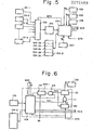
- a first embodiment of the present invention Designated at 101-1,... 101-n are a number n of weighing machines, each comprising a weighing hopper and a weight sensor, for weighing articles introduced into the weighing hopper.
- Analog voltage signals produced by the weighing machines 101-1,...., 101-n and indicative of the weights measured thereby are applied to a multiplexer 102, composed of analog switches or the like, for sucessively delivering these analog weight voltages to an A/D converter 103 in response to a selection signal, described below.
- the A/D converter 103 converts the analog voltage signal selected by the multiplexer 102 into a digital weight signal for application to an arithmetic control unit 104-1 constituted by a microcomputer or the like.
- Numeral 104-2 denotes a memory associated with the arithmetic control unit 104-1.
- a unit weight setting device 105 is connected to the arithmetic control unit 104-1 for setting the unit weight Wu of an article, as well as a number setting device 106 for setting the number Nc of articles to be counted. Also connected to the arithmetic control unit 104-1 is a weight setting device 107 for setting the total weight Wt of the number of articles set by the number setting device 106.
- the arithmetic control unit 104-1 delivers a selection signal WSS to the multiplexer 102.
- the multiplexer 102 responds to the selection signal WSS by delivering analog weight voltages from the weighing machines 101-1,..., 101-n successively to the A/D converter 103, which proceeds to convert the input analog sign.o-fs into digital weights for storage in a weight storage area 104-2a of memory 104-2.
- the arithmetic control unit 104-1 divides each weight value stored in the memory 104-2 by the unit weight Wu set by the unit weight setting device 105, and rounds off each quotient to the nearest whole number, thereby converting the weight of the articles contained in each of the weighing machines 101-1,..., 101-n into the number of articles contained in each weighing machine.
- the numbers of the articles are then stored in a number storage area 104-2b of the memory 104-2.
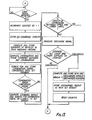
- the arithmetic control unit 104-1 successively generates all possible combination codes, adds the previously stored article numbers that are now specified by the combination codes, thereby to determine combined numbers of the articles, and stores the combined numbers and the combination codes as pairs in a combination storage area 104-2c of the memory 104-2.
- the arithmetic control unit 104-1 then compares the number Nc set by the setting device 106 with all of the combined numbers stored in the memory to retrieve the combination codes whose accompanying combined numbers coincide with the set number Nc. These combination codes are stored in a storage area 104-2d of the memory 104-2. When there is no combination that gives number coincidence, this is indicated by activating an alarm lamp or the like.
- the arithmetic control unit 104-1 computes combined weights by adding the weights of the articles in whichever of the weighing machines 101-1,...., 101-n are specified by the combination codes that provide coincidence between the combined numbers and the set number Nc, finds the combination code of that one such combined weight which is equal or cloest to the set weight as set by the weight setting device 107, and stores the found combination code and corresponding combined weight in a storage area 104-2e of the memory 104-2. This is the only pair stored in this storage area.
- the arithmetic control unit 104-1 then produces a discharge signal DCS which conforms to the combination code stored in the storage area 104-2e, whereupon the articles are released from the weighing machines corresponding to the discharge signal.
- the arithmetic control unit 104-1 now stores in memory the weight of the discharged articles, namely the combined weight equal or closest to the set weight. This stored weight serves as a new set weight. The storage of said weight ends the current counting cycle.
- the weights of the articles contained in the weighing machines 101-1,..., 101-n are stored in the manner described above, and are divided by the unit weight set by the unit weight setting device 105.
- the quotients are rounded off into data expressed in integers to thereby convert the weights of the articles in the weighing machines 101-1,..., 101-n into number thereof which are stored in memory.
- the arithmetic control unit 104-1 then retrieves the combination codes paired with the combined numbers, from among those computed based on the stored numbers, that coincide with the set number.
- This combination code is stored in memory. Now, from among the stored combinations, that which gives a combined weight equal or closest to the previously renewed set weight is retrieved to find the single combination code corresponding thereto.
- the arithmetic control unit 104-1 issues the discharge signal DCS conforming to this combination code.
- the combined weight of the articles just discharged is now stored in memory as an renewed set weight to replace the set weight previously renewed and stored. Thenceforth the set weights are renewed in similar fashion for each combinatorial counting cycle.
- the total weight of the articles discharged every combinatorial counting cycle is stored in memory as an renewed set weight and then, when the next combinatorial counting cycle is performed, articles are discharged from the weighing hoppers of those weighing machines corresponding to the combination whose combined weight is equal or closest to the set weight as last renewed and stored, said combination being selected from among those paired with a combined number coincident with the set number.
- Such a counting method prolongs the period of time during which the total weight of the discharged articles is substantially constant.
- the total weight of the articles discharged from the weighing machines varies as shown by the crosses marked (X) in the graph of Fig. 1. It will be appreciated that the total weight of the discharged articles is substantially constant for a longer period of time.
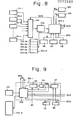
- Figs. 5, 6 and 7 describe the second embodiment of the invention, wherein a set weight is renewed every predetermined number of counting cycles, or at predetermined time intervals.
- Figs. 5 and 6 portions corresponding to those shown in Fig. 3 are designated by like reference characters.
- Fig. 6 illustrates the details of the arithmetic control unit 104-1.
- the embodiment shown in Fig. 5 is provided with a count setting device 108, connected to the arithmetic control unit 104-1, for determining how many times articles should be counted prior to updating a set weight.
- the arithmetic control unit 104-1 itself includes a combination computing circuit 109 for computing combinations based on weights supplied by the n-number of weighing machines 101-1,...,101-n through the muliplexer 102 and A/D converter 103.
- the inputs to the combination computing circuit 109 are such data as the unit weight Wu stored in the unit weight setting device 105 and the set number Nc stored in the number setting device 106.
- the arithmetic control unit 104-1 further includes a counter 110 whose status is counted up by one step each time the start signal STS is applied to the combination computing circuit 109, an AND gate 111 for delivering an output from the counter 110 when supplied with a comparison start command signal CST from the combination computing circuit 109, and a comparator 112 for comparing the count ot supplied by the counter 110 and the count ⁇ preset in the count setting device 108 and, when ⁇ and ⁇ coincide, for producing a memory renewal signal RNW as an output which is applied to an AND gate 113 and to the counter 110 to reset the latter.
- the AND gate 113 serves to deliver the combined weight, computed by the combination computing circuit 109, to a weight memory 114 when the memory renewal signal RNW arrives from the comparator 112.
- the weight memory 114 stores the data Wt set by the weight setting device 107 until the data arrives from the combination computing unit 109 via the AND gate 113.
- the multiplexer 102 responds to the selection signal WSS by delivering analog weight voltages from the weighing machines 101-1,..., 101-n successiveively to the A/D converter 103, which proceeds to convert the input analog signals into digital weight signals for storage in the weight storage area 104-2a via the combination computing circuit 109.
- the latter divides each weight value stored in the memory 104-2 by the unit weight Wu set by the unit weight setting device 105, and rounds off each quotient to the nearest whole number, thereby converting the weight of the articles contained in each of the weighing machines 101-1,..., 101-n into the number of articles contained in each weighing machine.
- the numbers of the articles are then stored in the number storage area 104-2b of the memory 104-2.
- the combination computing circuit 109 successively generates all possible combination codes, adds the previously stored article numbers (the article numbers stored in memory 104-2) that are specified by the combination codes, thereby to determine combined numbers of the articles, and stores the combined numbers and the combination codes as pairs in the combination storage area 104-2c of the memory 104-2.
- the combination computing circuit 109 theft compares the number Nc set by the setting device 106 with all of the combined numbers stored in the memory to retrieve the combination codes whose accompanying combined numbers coincide with the set number Nc.
- These combination codes are stored in a storage area 104-2d of the memory 104-2. When there is no combination that gives number coincidence, this is indicated by activating an alarm or the like.
- the combination computing circuit 109 computes combined weights by adding the weights of the articles in whichever of the weighing machines 101-1,.., 101-n are specified by the combination codes that provide coincidence between the combined numbers and the set number Nc, finds the combination code of one of such combined weights which is equal or closest to the set weight Wt as set by the weight setting device 107, and stores the found combination code and corresponding combined weight as a pair in the storage area 104-2e of the memory 104-2. This is the only pair stored in this storage area.
- the combination computing circuit 109 then produces a discharge signal DCS which conforms to the combination code stored in the storage area 104-2e, whereupon the articles are released from the weighing machines corresponding to the discharge signal. These articles, the number of which will be equal to the set number Nc, are delivered to the packaging machine.
- the combination computing circuit 109 now delivers the comparison start command signal CST to the AND gate 111, so that the number of start signals STS counted by the counter 110 is applied to the comparator 112.
- the comparator 112 now compares the count supplied by counter 110 with the count preset by the count setting device 108. If the number of counting operations counted by the counter 110 has not reached the count set by the count setting device 108, then the comparator 112 does not produce the memory renewal output signal RNW. Therefore, the weight data stored in the weight memory 114 is not renewed. This ends the current counting cycle.
- the next step is to retrieve the sole combination which has a combined number of articles equal to the set number Nc, the combined weight of which is equal or closest to the set weight Wt stored in the weight memory 114.
- the discharge signal DCS conforming to this combination is applied to the combination computing circuit 109.
- the combination computing circuit 109 sends the comparison start command signal CST to the AND gate 111. If the number of counting operations as counted by the counter 110 still falls short of the count set by the count setting device 108, then the counting operation ends in the manner described above.
- the foregoing cycle of operation is repeated until the count which the counter 110 applies to the comparator 112 coincides with the count set by the count setting device 108.
- the comparator 112 produces the memory renewal signal RNW which is applied to the AND gate 113 and to the counter 110 at the same time to reset the same.
- the AND gate 113 in response to the signal RNW, supplies the weight memory 114 with data indicative of the total weight of the articles just discharged, thereby renewing or updating the set weight stored in the weight memory 114. Thenceforth the set weight is renewed in a similar manner each time a predetermined number of the counting operations is performed.
- the operating for renewing the set weight has been described as being carried out each time a preset number of counting cycles are performed. It should be noted, however, that the set weight renewal can be executed at a predetermined time interval as set by a time or the like, or by providing a clock pulse generating circuit for supplying clock pulses to the counter 110 in place of the start signal STS.
- an upper weight limit setting device 115 connected to the arithmetic control unit 104-1 for setting an upper weight limit B on the set weight
- a lower weight limit setting device connected to the arithmetic control unit 104-1 for setting a lower weight limit C on the set weight
- the details of the arithmetic control unit 104-1 of Fig. 8 are illustrated in the block diagram of Fig. 9.
- the arithmetic control unit 104-1 includes a comparator 117 for comparing a total weight A, based on a combination computed by the combination computing circuit 109, with upper and lower limits B, C on a set weight Wt, the upper and lower limits B, C being set by the setting device 115, 116, respectively, and for delivering a memory renewal signal RNW to an AND gate 118 and to the combination computing circuit 109 when the combined weight A is less than the upper limit B and greater than the lower limit C, that is, when the inequality B>A>C holds.
- the AND gate 118 serves to deliver the combined weight data A, computed by the combination computing circuit 109, to the weight memory 114 when the memory renewal signal RNW arrives from the comparator 117.
- the weight memory 114 stores the weight data Wt set by the weight setting device 107 until the end of the first counting cycle.
- the combination computing circuit 109 converts the input weights arriving from the weighing machines into the numbers of the articles contained in the weighing machines thereby to compute combinations, and retrieves the sole combination which has a combined number of articles equal to the set number Nc, the combined weight of which is equal or closest to the set weight Wt stored in the weight memory 114.
- This combination code and accompanying combined weight A are stored, as a pair, in the memory 104-2. This is the only combination code and combined weight stored.
- the stored weight A is applied to the comparator 117 where it is compared with the set weight upper and lower limits B, C set by the upper and lower limit setting devices 115, 116, respectively. If the combined weight falls within the range defined by these limits, then the comparator 117 applies the memory renewal signal RNW to the combination computing circuit 109 and to the AND gate 118. The latter then provides the weight memory 114 with the above-mentioned stored combined weight A, found by the combination computing circuit 109, thereby renewing the set weight.
- the combination computing circuit 109 also delivers the discharge signal DCS conforming to the combination code of the stored combined weight, whereupon the articles are released from the weighing machines corresponding to the discharge signal. These articles, the number of which will be equal to the set number Nc, are delivered to the packaging machine, thereby ending the counting cycle.
- the arithmetic control unit 104-1 When the start signal STS from the packaging machine enters the arithmetic control unit 104-1, the weights of the articles contained in the weighing machines 101-1,.., 101-n are stored in the memory 104-2, these weights are divided by the unit weight Wu stored in the unit weight setting device 105, the quotients are rounded off to the nearest whole number to convert the weights into the number of the articles contained in the weighing machines 101-1,..., 101-n, and the number of the articles are stored in memory.
- the next step is to retrieve the sole combination which has a combined number of articles equal to the set number Nc, and of which the combined weight is equal or closest to the renewed set weight stored in the weight memory 114.
- the value indicative of this combined weight is delivered to the weight memory 114 to renew the set weight stored there.
- the combination computing circuit 109 delivers the discharge signal DCS conforming to the combination code of the stored combined weight, whereupon the articles are released from the weighing machines corresponding to the discharge signal.
- These articles, the number of which will be equal to the set number Nc are delivered to the packaging machine. Thereafter the set weight will be renewed in the manner described above so long as the combined weight found every counting cycle falls within the preset limits.
- the comparator 117 When the combined weight found by the combination computing circuit 109 and delivered to the comparator 117 does not fall within the upper and lower set weight limits set by the upper and lower limit setting circuits 115, 116, respectively, the comparator 117 does not send the memory renewal signal RNW to the AND gate 118 and combination computing circuit 109 and, hence, the set weight is not renewed. Moreover, the combination computing circuit 109 does not produce the signal DCS, so that the counting operation is halted without articles being discharged from the weighing machines.
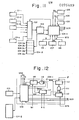
- a fourth embodiment of the present invention will be described with reference to Figs, 11, 12 and 13.
- a set weight is renewed at every predetermined number of counting cycles, or at predetermined time intervals, if the combined weight falls within a preset range.
- Fig. 11 is a block diagram illustrating the overall system
- Fig. 12 is a block diagram showing the details of the arithmetic conrol unit 104-1 in this embodiment.
- the arithmetic control unit 104-1 includes a three-input AND gate 119 for providing the weight memory 114 with the combined weight A, found by the combination computing circuit 109 and present at one input terminal to the AND gate, when a first memory renewal signal RNW from the comparator 112 and a second memory renewal signal RNW' from the comparator 117 are present at the other two inputs to the AND gate.
- the combination computing circuit 109 converts the input weights arriving from the weighing machines into the numbers of the articles contained in the weighing machines thereby to compute combinations, and retrieves the sole combination which has a combined number of articles equal to the set number Nc, the combined weight of which is equal or closest to the set weight Wt stored in the weight memory 114.
- This combination code and accompanying combined weight A are stored, as a pair, in the memory 104-2. This is the only combination code and combined weight stored.
- the stored weight A is applied to the comparator 117 where it is compared with the set weight upper and lower limits B, C set by the upper and lower limit setting devices 115, 116 respectively. If the combined weight falls within the range defined by these limits, then the comparator 117 applies the second memory renewal signal RNW' to the combination computing circuit 109 and to the AND gate 119. Concurrently, the combination computing circuit 109 produces the discharge signal DCS conforming to the combination code of the stored combined weight, as well as the comparison start command signal CST which is applied to the AND gate 111. As a result, the articles are released from the weighing machines corresponding to the discharge signal. These articles, the number of which will be equal to the set number Nc, are delivered to the packaging machine.
- the AND gate 111 supplies the comparator 112 with the count indicative of the number of counting cycles that have been performed, as counted by the counter 110.
- the comparator 112 then proceeds to compare the count supplied by counter 110 with the count preset by the count setting device 108. If the number of counting operations counted by the counter 110 has not reached the count set by the count setting device 108, the the comparator 112 does not produce the first memory renewal output signal RNW. Therefore, the lack of coincidence between the first and second memory renewal signals RNW, RNW' from the respective comparators 112, 117 causes the AND gate 114 to block the delivery of the combined weight, found by the combination computing circuit 109, to the weight memory 114. Thus, the weight data stored in the weight memory 114 is not renewed. This ends the current counting cycle.
- the next step is to retrieve the sole combination which has a combined number of articles equal to the set number Nc, the combined weight of which is equal or closest to the set weight Wt stored in the weight memory 114.
- the comparator 117 delivers the signal RNW' to the comparison computing circuit 109 and to the AND gate 119.
- the combination computing circuit 109 therefore produces the discharge signal DCS and the comparison start command signal CST, which is applied to the AND gate 11. Accordingly, as before, the comparator compares the number of counting operations provided by the counter 110 with the count set by the count setting device 108. If the number of counting operations as counted by the counter 110 still falls short of the count set by the count setting device 108, then the counting operation ends in the manner described above.
- the comparator 117 When the combined weight found by the combination computing circuit 109 and delivered to the comparator 117 does not fall within preset limits, the comparator 117 does not produce the second memory renewal signal RNW'. As a result, the combination computing circuit 109 does not produce the discharge DCS, so that the counting operation is halted without articles being discharged from the weighing machines.
- the comparator 112 prodices the first memory renewal signal RNW which is applied to the AND gate 119 and to the counter 110, which is reset thereby. Since coincidence between signal RNW and the second memory renewal signal RNW' from the comparator 117 is now established at AND gate 119, the latter permits the combined weight (discharged weight ) found by the combination computing circuit 109 to enter the weight memory 114, thereby renewing the set weight stored there.
- the set weight is renewed every predetermined number of counting operations if the combined weight obtained from the combination computing circuit 109 is within the set limits. It should be noted that an arrangement is possible wherein the set weight may be renewed at predetermined intervals set by a timer or the like if the combined weight at such time falls within the set limits.
- the combination control unit 104-1 divides the weight of the discharge articles by the number of discharge articles, namely by the set number, to compute a new unit weight, thereby allowing the unit weight to be renewed. With such an arangement the set weight (total weight) would be renewed either before or after the renewal of the unit weight.
- combinations are sought that give coincidence between the combined numbers of articles and the particular set number.
- it is also permissable to find the combination that gives combined numbers equal or closest to the set number with the proviso that the revision of the set weight in such case is carried out with the weight of the articles discharged at such time serving as the new set weight only when the combination of combined numbers that is found is equal to the set number. This will prevent the set weight from varying too widely.
- the combination sought is equal or closest to the set number
- the articles discharged correspond to a combination of combined numbers closest to the set number because a combination of combined numbers equal to the set number cannot be found.
- the unit weight, found by dividing the weight of the discharged articles by the number of discharged articles, may be multiplied by a predetermined set number to provide a value which may then be stored as a new set weight.
- a combination of combined numbers equal to the set weight is found, however, the weight of the articles discharged at such time is stored as the new set weight.
- n numbers of articles are determined by converting the n weights measured by the n weighing machines
- a single weighing machine may be used to weigh a plurality of batches of articles in a single combinatorial weighing operation.
- the n weights may be determined by using a single weighing machine or a plurality of weighing machines, and the n numbers may be found by converting the determined weights into numbers.
- An embodiment of the present invention as described and illustrated hereinabove can advantageously comprise weighing a multiplicity of articles by one or a plurality of weighing machines, dividing the resulting plurality of weights by a unit weight to convert the weights into respective numbers, finding combinations of these numbers to compute combined numbers, finding the single combination of which the combined numbers are equal or closest to a set number and of which the combined weight is equal or closest to a set weight, renewing the set weight every counting operation, or whenever predetermined conditions are satisfied, to provide a new set weight for use in the next counting operation. Therefore, when counting articles the unit weight whereof varies gradually with time, an embodiment of the invention can serve to prolong the period of time during which the total weight of discharged articles is substantially constant.
- a predetermined condition mentioned above is a predetermined number of counting operations or a predetermined length of time, moreover, then needless renewal steps can be eliminated, as when there is almost no change in a set weight despite a renewal performed every counting operation. Furthermore, if a predetermined condition is that a combined weight should fall within a preset range, then it becomes possible to prevent a situation where a combined weight, which for some reason exhibits an abnormally large weight variation, is stored in memory as a new set weight. In other words, this prevents a large fluctuation in the set weight, so that normally only packaged articles of a net weight within the set range will be obtained.
Landscapes
- Physics & Mathematics (AREA)
- General Physics & Mathematics (AREA)
- Engineering & Computer Science (AREA)
- Mathematical Physics (AREA)
- Theoretical Computer Science (AREA)
- Basic Packing Technique (AREA)
- Weight Measurement For Supplying Or Discharging Of Specified Amounts Of Material (AREA)
Applications Claiming Priority (2)
| Application Number | Priority Date | Filing Date | Title |
|---|---|---|---|
| JP149754/81 | 1981-09-22 | ||
| JP56149754A JPS5850428A (ja) | 1981-09-22 | 1981-09-22 | 計数方法 |
Publications (3)
| Publication Number | Publication Date |
|---|---|
| EP0075489A2 true EP0075489A2 (de) | 1983-03-30 |
| EP0075489A3 EP0075489A3 (en) | 1984-08-22 |
| EP0075489B1 EP0075489B1 (de) | 1988-03-30 |
Family
ID=15482014
Family Applications (1)
| Application Number | Title | Priority Date | Filing Date |
|---|---|---|---|
| EP82305000A Expired EP0075489B1 (de) | 1981-09-22 | 1982-09-22 | Gruppierung von Artikeln in Übereinstimmung mit vorgewählten Anforderungen nach Zahl/Gewicht |
Country Status (5)
| Country | Link |
|---|---|
| US (1) | US4466499A (de) |
| EP (1) | EP0075489B1 (de) |
| JP (1) | JPS5850428A (de) |
| AU (1) | AU542633B2 (de) |
| DE (1) | DE3278294D1 (de) |
Cited By (3)
| Publication number | Priority date | Publication date | Assignee | Title |
|---|---|---|---|---|
| GB2131963A (en) * | 1982-12-17 | 1984-06-27 | Henry John Steel | Combination weighing machines and method |
| EP0160554A3 (en) * | 1984-04-26 | 1986-08-27 | Ishida Scales Mfg. Co. Ltd. | Automatic weighing machine |
| EP0312272A3 (de) * | 1987-10-09 | 1990-10-24 | Ishida Scales Mfg. Co. Ltd. | Kombinatorische Zählmethode und Wägeapparat hierfür |
Families Citing this family (7)
| Publication number | Priority date | Publication date | Assignee | Title |
|---|---|---|---|---|
| JPS5841325A (ja) * | 1981-09-04 | 1983-03-10 | Ishida Scales Mfg Co Ltd | 計量方法 |
| JPS59170728A (ja) * | 1983-03-17 | 1984-09-27 | Ishida Scales Mfg Co Ltd | 組合せ計量方式 |
| JPS6097218A (ja) * | 1983-10-31 | 1985-05-31 | Yamato Scale Co Ltd | 組合せ計量方法 |
| US4649494A (en) * | 1984-06-29 | 1987-03-10 | Pennwalt Corporation | Method for maintaining zero calibration values in article sorting machine |
| JPS62133323A (ja) * | 1985-12-05 | 1987-06-16 | Yamato Scale Co Ltd | 組合せ秤 |
| US4909338A (en) * | 1989-06-12 | 1990-03-20 | Ncr Corporation | Method and apparatus for scale calibration and weighing |
| CN116124262A (zh) * | 2023-03-17 | 2023-05-16 | 江苏云涌电子科技股份有限公司 | 一种带补偿的单物品称重计数方法 |
Family Cites Families (6)
| Publication number | Priority date | Publication date | Assignee | Title |
|---|---|---|---|---|
| US3862666A (en) * | 1972-05-02 | 1975-01-28 | Triangle Package Machinery Co | Servo control system for filling machine weight setting |
| US4043412A (en) * | 1974-09-30 | 1977-08-23 | National Controls, Inc. | Counting scale and method |
| JPS53141072A (en) * | 1977-05-15 | 1978-12-08 | Shinkou Denshi Kk | Method for counting number of parts by way of scale |
| JPS5690219A (en) * | 1979-12-24 | 1981-07-22 | Yamato Scale Co Ltd | Combination scale |
| JPS56142419A (en) * | 1980-04-08 | 1981-11-06 | Teraoka Seiko Co Ltd | Recounting device for digital display counting scale |
| JPS5759121A (en) * | 1980-09-25 | 1982-04-09 | Ishida Scales Mfg Co Ltd | Counting method |
-
1981
- 1981-09-22 JP JP56149754A patent/JPS5850428A/ja active Granted
-
1982
- 1982-09-16 AU AU88445/82A patent/AU542633B2/en not_active Ceased
- 1982-09-20 US US06/419,924 patent/US4466499A/en not_active Expired - Fee Related
- 1982-09-22 EP EP82305000A patent/EP0075489B1/de not_active Expired
- 1982-09-22 DE DE8282305000T patent/DE3278294D1/de not_active Expired
Cited By (4)
| Publication number | Priority date | Publication date | Assignee | Title |
|---|---|---|---|---|
| GB2131963A (en) * | 1982-12-17 | 1984-06-27 | Henry John Steel | Combination weighing machines and method |
| EP0160554A3 (en) * | 1984-04-26 | 1986-08-27 | Ishida Scales Mfg. Co. Ltd. | Automatic weighing machine |
| US4645020A (en) * | 1984-04-26 | 1987-02-24 | Ishida Scales Mfg. Co., Ltd. | Combinatorial weighing machine with weighing and counting modes |
| EP0312272A3 (de) * | 1987-10-09 | 1990-10-24 | Ishida Scales Mfg. Co. Ltd. | Kombinatorische Zählmethode und Wägeapparat hierfür |
Also Published As
| Publication number | Publication date |
|---|---|
| EP0075489B1 (de) | 1988-03-30 |
| DE3278294D1 (en) | 1988-05-05 |
| EP0075489A3 (en) | 1984-08-22 |
| US4466499A (en) | 1984-08-21 |
| AU8844582A (en) | 1983-03-31 |
| AU542633B2 (en) | 1985-02-28 |
| JPS5850428A (ja) | 1983-03-24 |
| JPH0158449B2 (de) | 1989-12-12 |
Similar Documents
| Publication | Publication Date | Title |
|---|---|---|
| EP0071473B1 (de) | Kombinatorisches Portionieren von Artikeln | |
| US4534428A (en) | Vibratory feeder control for a weighing system | |
| EP0084968B1 (de) | Wägemethode und Vorrichtung hierfür | |
| US4466499A (en) | Combinatorial counting method | |
| US4467880A (en) | Combinatorial weighing apparatus | |
| EP0076167B1 (de) | Kombinatorisches Wiegen oder Zählen von Artikeln | |
| US4396078A (en) | Weighing or counting method with some unfilled hoppers | |
| US4522274A (en) | Combinatorial weighing method | |
| US4566070A (en) | Method of counting parts | |
| EP0576223B1 (de) | Teilmengenwaage mit besonderer Zufuhrsteuerung | |
| US4465149A (en) | Method of zero adjustment for combinatorial weighing or counting system | |
| EP0124370B1 (de) | Kombinatorische Wiegemethode und Apparat | |
| EP0127326B1 (de) | Kombinatorisches Wägeresfahren und Vorrichtung | |
| US4739846A (en) | Counting method | |
| US4850442A (en) | Zero-point adjustment of weighing device | |
| EP1424542B1 (de) | Kombinationswaage | |
| EP0119854B1 (de) | Kombinatorische Wiegemethode und Apparat | |
| EP0103476B1 (de) | Kombinatorische Wägemethode und Apparat hierfür | |
| US4610323A (en) | Combination weighing system | |
| EP0125080B1 (de) | Kombinatorische Wiegemethode und Apparat | |
| US4552237A (en) | Combinatorial weighing method and apparatus | |
| US4625817A (en) | Method of zero adjustment for combinatorial weighing or counting system | |
| EP0643288A1 (de) | Verfahren und Apparat zur kombinatorischen Wägung | |
| GB2085172A (en) | Automatic weighing apparatus | |
| EP0138593A2 (de) | Kombinatorische Wägung |
Legal Events
| Date | Code | Title | Description |
|---|---|---|---|
| PUAI | Public reference made under article 153(3) epc to a published international application that has entered the european phase |
Free format text: ORIGINAL CODE: 0009012 |
|
| AK | Designated contracting states |
Designated state(s): DE FR GB IT |
|
| PUAL | Search report despatched |
Free format text: ORIGINAL CODE: 0009013 |
|
| AK | Designated contracting states |
Designated state(s): DE FR GB IT |
|
| 17P | Request for examination filed |
Effective date: 19841220 |
|
| 17Q | First examination report despatched |
Effective date: 19860221 |
|
| GRAA | (expected) grant |
Free format text: ORIGINAL CODE: 0009210 |
|
| AK | Designated contracting states |
Kind code of ref document: B1 Designated state(s): DE FR GB IT |
|
| REF | Corresponds to: |
Ref document number: 3278294 Country of ref document: DE Date of ref document: 19880505 |
|
| ET | Fr: translation filed | ||
| ITF | It: translation for a ep patent filed | ||
| PLBE | No opposition filed within time limit |
Free format text: ORIGINAL CODE: 0009261 |
|
| STAA | Information on the status of an ep patent application or granted ep patent |
Free format text: STATUS: NO OPPOSITION FILED WITHIN TIME LIMIT |
|
| 26N | No opposition filed | ||
| PGFP | Annual fee paid to national office [announced via postgrant information from national office to epo] |
Ref country code: GB Payment date: 19900904 Year of fee payment: 9 |
|
| PGFP | Annual fee paid to national office [announced via postgrant information from national office to epo] |
Ref country code: DE Payment date: 19900912 Year of fee payment: 9 |
|
| PGFP | Annual fee paid to national office [announced via postgrant information from national office to epo] |
Ref country code: FR Payment date: 19900920 Year of fee payment: 9 |
|
| ITTA | It: last paid annual fee | ||
| PG25 | Lapsed in a contracting state [announced via postgrant information from national office to epo] |
Ref country code: GB Effective date: 19910922 |
|
| GBPC | Gb: european patent ceased through non-payment of renewal fee | ||
| PG25 | Lapsed in a contracting state [announced via postgrant information from national office to epo] |
Ref country code: FR Effective date: 19920529 |
|
| PG25 | Lapsed in a contracting state [announced via postgrant information from national office to epo] |
Ref country code: DE Effective date: 19920602 |
|
| REG | Reference to a national code |
Ref country code: FR Ref legal event code: ST |