EP0075521A2 - Système d'essuie-glace - Google Patents
Système d'essuie-glace Download PDFInfo
- Publication number
- EP0075521A2 EP0075521A2 EP82401719A EP82401719A EP0075521A2 EP 0075521 A2 EP0075521 A2 EP 0075521A2 EP 82401719 A EP82401719 A EP 82401719A EP 82401719 A EP82401719 A EP 82401719A EP 0075521 A2 EP0075521 A2 EP 0075521A2
- Authority
- EP
- European Patent Office
- Prior art keywords
- arm
- rocker arm
- rotoid
- connection
- guide arm
- Prior art date
- Legal status (The legal status is an assumption and is not a legal conclusion. Google has not performed a legal analysis and makes no representation as to the accuracy of the status listed.)
- Granted
Links
Images


Classifications
-
- B—PERFORMING OPERATIONS; TRANSPORTING
- B60—VEHICLES IN GENERAL
- B60S—SERVICING, CLEANING, REPAIRING, SUPPORTING, LIFTING, OR MANOEUVRING OF VEHICLES, NOT OTHERWISE PROVIDED FOR
- B60S1/00—Cleaning of vehicles
- B60S1/02—Cleaning windscreens, windows or optical devices
- B60S1/04—Wipers or the like, e.g. scrapers
- B60S1/32—Wipers or the like, e.g. scrapers characterised by constructional features of wiper blade arms or blades
- B60S1/34—Wiper arms; Mountings therefor
- B60S1/3402—Wiper arms; Mountings therefor with means for obtaining particular wiping patterns
- B60S1/3409—Wiper arms; Mountings therefor with means for obtaining particular wiping patterns the wiper arms consisting of two or more articulated elements
Definitions
- the present invention relates to a windscreen wiper system intended for vehicles, in particular for road vehicles.
- This system is characterized by a non-circular trajectory of any of the points of the brush (es) associated with it. Such a trajectory is sought to improve visibility and wiping quality compared to conventional systems with a circular trajectory.
- the proposed invention retains a mechanical organization associating two closed kinematic chains, certain elements of which are common, and which constitute a mechanism with two input movements.
- a first kinematic chain is formed a shaft in rotation relative to the body, a main guide arm articulated on this shaft by a rotary link, a rocker arm articulated on the one hand on the guide arm and on the other hand on the brush - possibly split - by means of rotoid connections. All the elements of this chain are entirely contained in a plane containing the axis of the tree or parallel to this axis; this plane is driven by an oscillating movement through the shaft which constitutes the input element of this first kinematic chain.
- the second kinematic chain comprises at least one element common to the first chain - the rocker arm, as well as its own elements - a secondary guide arm articulated at two of its points, each articulation comprising at least two rotoid connections, one of the aforementioned joints connecting it to the rocker arm.
- That of the two articulations of the secondary guide arm which does not ensure the connection of said arm with the rocker arm, can connect said arm to a bent shaft mounted to pivot relative to the body.
- the bent shaft then constitutes the second input element of the mechanism.
- the arrangement of the bent shaft is generally arbitrary with respect to the axis of the input shaft of the first chain; consequently, the movement of the secondary guide arm is spatial and takes place outside the oscillating plane which contains the brush.
- the function of the first kinematic chain is to impose at all times the angular position of the brush , that of the second chain is to compel a given point on the broom to describe a trajectory which deviates from a circumference.
- This difference is defined by the eccentricity of the bent shaft, by the relative arrangement of the rocker joints as well as by that of the axes of the trees of the two kinematic links.
- a second advantage of the invention results from the fact that the brush is articulated on a rocker arm which can be of small size and that this rocker arm is articulated on two arms, one of which pivots directly on the bodywork. This gives satisfactory guidance of the brush which is favorable to the quality of the wiping. This guidance by two arms is obtained without the visibility of the driver being deteriorated compared to conventional guidance: the instantaneous positions of the secondary guide arm deviate very little from the main guide arm.
- a third advantage of the invention resides in the possibility offered by the proposed mechanical organization of obtaining a large deviation from the circular trajectory without this resulting in a pivoting of the brush around one of its material points, this which is not the case for most of the mechanisms proposed previously.
- a fourth advantage of the invention resides in the low mass of the elements of the system which create the deviations from the circular trajectory: these deviations are thus obtained without giving rise to excessive inertia forces at high scanning speeds.
- the mechanism which is the subject of the invention comprises a geared motor and two transmissions associated, on the one hand, with the geared motor and, on the other hand, with the two input elements of the mechanism.
- the transmission which requires the oscillation of the main guide arm and the brush, transforms the rotational movement continues the motor in an alternating rotational movement of an amplitude equal to that of the sweep.
- the second transmission can be similar to the previous one; it can also deliver a continuous rotation movement whose periodicity is equal or proportional to that of the oscillation movement of the brush.
- gear motor In another embodiment, it is also possible to complete the gear motor with two transmissions arranged not in parallel, but in series. One of the transmissions then receives its input movement not directly from the gear motor but from the other transmission.
- the desired effects can be obtained by simplifying the system as follows: the eccentricity of the bent shaft of the second kinematic chain is canceled, whose movement and transmission which creates it thus become superfluous.
- the specific elements of the second kinematic chain are then reduced to a single articulated secondary guide arm, on the one hand, at the rocker arm and, on the other hand, on an element fixed relative to the vehicle body.
- the system which is the subject of the invention can be used to carry out scans with several brushes.
- the system which is the subject of the invention can be used to carry out scans with several brushes.
- many systems are used as there are non-circular paths to be carried out independently.
- the drawing illustrates, by way of example, a particular embodiment in accordance with the invention, comprising a single brush and a single main guide arm.
- the brush 1 is removably mounted on the rocker arm 2 by means of a conventional articulation.
- the rocker arm 2 is linked to the guide arms 3 and 4 by the respective joints 5 and 6;
- the articulation 5 is a rotoid connection with an axis perpendicular to the mean plane of the rocker arm 2;
- the joint 6 is a spherical connection.
- the rocker / brush and rocker / main guide arm articulation axes are parallel; the articulation point 6 is disposed between the two aforementioned axes.
- the main guide arm 3 is articulated on the shaft 7 by means of a rotoid connection 8 and an assembly 9 as in traditional mechanisms.
- the secondary guide arm 4 is articulated on the bent shaft 10 by means of two round connections 11 and 12 of perpendicular axes, connected by an intermediate lever 13.
- the shaft 7 and the bent shaft 10 are guided in rotation relative to the body by the rotoid guides 14 and 15; their movements are synchronized by a transmission 16.
- the articulation 6 is provided by two rotunda links, one of which is parallel to the axis 5.
Landscapes
- Engineering & Computer Science (AREA)
- Mechanical Engineering (AREA)
- Transmission Devices (AREA)
- Vehicle Cleaning, Maintenance, Repair, Refitting, And Outriggers (AREA)
Abstract
Description
- La présente invention est relative à un système d'essuie-glace destiné aux véhicules, notamment aux véhicules routiers. Ce système est caractérisé par une trajectoire non-circulaire de l'un quelconque des points du ou des balai(s) qui lui sont associés. Une telle trajectoire est recherchée pour améliorer la visibilité et la qualité d'essuyage par rapport aux systèmes classiques à trajectoire circulaire.
- De nombreux systèmes à trajectoire non-circulaire ont été proposés. On peut notamment citer ceux qui sont décrits dans les brevets français 2.239.873, 2.194.173, 2.178.682, 2.178.683. Ces systèmes sont notamment caractérisés par la présence d'un seul balai articulé sur un seul bras porte-balai dont on déplace l'axe de rotation.
- D'autres systèmes d'essuie-glace destinés à obtenir un champ d'essuyage de forme rectangulaire ont également été proposés. Il s'agit essentiellement des systèmes définis par les brevets 2.131.446et 2.144.269 . L'organisation de ces systèmes est sensiblement différente de celle décrite dans les brevets rappelés à l'alinéa précédent : on y trouve essentiellement, outre un balai et un bras porte-balai, un bras de guidage ; l'organisation mécanique de ces éléments est telle que l'articulation du balai sur le bras porte-balai décrit une trajectoire rectiligne et que le bras de guidage maintient l'axe du balai selon une direction fixe perpendiculaire à cette trajectoire.
- Aucun des systèmes que l'on vient d'évoquer n'a connu jusqu'à présent d'application, essentiellement parce que leur construction s'est avérée peu économique, leur encombrement prohibitif ou leur longévité problématique.
- L'invention proposée retient une organisation mécanique associant deux chaînes cinématiques fermées dont certains éléments sont communs, et qui constituent un mécanisme à deux mouvements d'entrée.
- Une première chaîne cinématique est constituée d'un arbre en rotation par rapport à la carrosserie, d'un bras de guidage principal articulé sur cet arbre par une liaison rototde, d'un culbuteur articulé d'une part sur le bras de guidage et d'autre part sur le balai -éventuellement dédoublé- au moyen de liaisons rotoides. L'ensemble des éléments de cette chaîne est entièrement contenu dans un plan contenant l'axe de l'arbre ou parallèle à cet axe ; ce plan est animé d'un mouvement d'oscillation par l'intermédiaire de l'arbre qui constitue l'élément d'entrée de cette première chaîne cinématique.
- La deuxième chaîne cinématique comporte au moins un élément commun à la première chaîne - le culbuteur-, ainsi que des éléments propres - un bras de guidage secondaire articulé en deux de ses points, chaque articulation comportant au moins deux liaisons rotoides, l'une des articulations précitées le reliant aux culbuteur.
- Dans une première variante, celle des deux articulations du bras de guidage secondaire, qui n'assure pas la liaison dudit bras avec le culbuteur, peut relier ledit bras à un arbre coudé monté pivotant par rapport à la carrosserie. L'arbre coudé constitue alors le second élément d'entrée du mécanisme. La disposition de l'arbre coudé est généralement quelconque par rapport à l'axe de l'arbre d'entrée de la première chaîne ; par conséquent, le mouvement du bras de guidage secondaire est spatial et s'exerce en dehors du plan oscillant qui contient le balai.
- Dans le cas de référence où le balai essuie un pare-brise plan, perpendiculaire à l'arbre d'entrée et parallèle au bras de guidage principal, la fonction de la première chaîne cinématique est d'imposer à tout instant la position angulaire du balai, celle de la seconde chaîne est d'astreindre un point donné du balai à décrire une trajectoire qui s'écarte d'une circonférence. Cet écart est défini par l'excentricité de l'arbre coudé, par la disposition relative des articulations du culbuteur ainsi que par celle des axes des arbres des deux chatnes cinématiques.
- Il en résulte un premier avantage de l'invention : en effet, par une disposition judicieuse de ces articulations, on réalise une amplification du mouvement de l'arbre coudé qui impose l'écart à la trajectoire circulaire ; un écart important peut être obtenu par une faible excentricité et il en résulte une implantation facile du mécanisme dans la carrosserie.
- Un second avantage de l'invention résulte de ce que le balai est articulé sur un culbuteur qui peut être de petite dimension et que ce culbuteur est articulé sur deux bras dont l'un pivote directement sur la carrosserie. On obtient ainsi un guidage satisfaisant du balai qui est favorable à la qualité de l'essuyage. Ce guidage par deux bras est obtenu sans que la visibilité du conducteur soit détériorée par rapport au guidage classique : les positions instantanées du bras de guidage secondaire s'écartent en effet assez peu du bras de guidage principal.
- Un troisième avantage de l'invention réside dans la possibilité qu'offre l'organisation mécanique proposée d'obtenir un écart important à la trajectoire circulaire sans qu'il en résulte un pivotement du balai autour de l'un de ses points matérialisés, ce qui n'est pas le cas de la plupart des mécanismes proposés antérieurement.
- Un quatrième avantage de l'invention réside dans la faible masse des éléments du système qui créent les écarts à la trajectoire circulaire : ces écarts sont ainsi obtenus sans susciter des efforts d'inertie excessifs aux grandes vitesses de balayage.
- Dans un mode de réalisation, le mécanisme objet de l'invention comprend un moto-réducteur et deux transmissions associées, d'une part, au moto-réducteur et, d'autre part, aux deux éléments d'entrée du mécanisme. La transmission, qui impose l'oscillation du bras de guidage principal et du balai, transforme le mouvement de rotation continue du moteur en un mouvement de rotation alternative d'une amplitude égale à celle du balayage. La seconde transmission peut être analogue à la précédente ; elle peut également délivrer un mouvement de rotation continue dont la périodicité est égale ou proportionnelle à celle du mouvement d'oscillation du balai.
- Dans un autre mode de réalisation, il est également possible de compléter le moto-réducteur par deux transmissions disposées non pas en parallèle, mais en série. L'une des transmissions reçoit alors son mouvement d'entrée non pas directement du moto-réducteur mais de l'autre transmission.
- Dans une deuxième variante du système objet de l'invention, et pour certaines proportions de pare-brise, les effets recherchés peuvent être obtenus en simplifiant le système comme suit : on annule l'excentricité de l'arbre coudé de la seconde chaîne cinématique, dont le mouvement et la transmission qui le crée deviennent ainsi superflus. Les éléments propres de la deuxième chaîne cinématique se ramènent alors à un seul bras de guidage secondaire articulé, d'une part, au culbuteur et, d'autre part, sur un élément fixe par rapport à la carrosserie du véhicule.
- Dans des applications plus complexes, le système objet de l'invention peut être utilisé pour réaliser des balayages à plusieurs balais. Dans ces applications, on utilise autant de systèmes qu'il y a de trajectoires non-circulaires à réaliser indépendamment.
- Le dessin illustre, à titre d'exemple, une réalisation particulière conforme à l'invention, comportant un seul balai et un seul bras de guidage principal.
- Sur ce dessin :
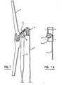
- - la figure 1 présente la partie supérieure du système dans un plan sensiblement perpendiculaire au pare-brise plan de référence ;
- - la figure lA présente le détail de l'articulation du bras de guidage secondaire sur le culbuteur ;
- - la figure 2 présente, en coupe partielle, la partie inférieure du système de la figure 1 ;
- - la figure 3 présente une vue du système des figures 1 et 2 dans un plan parallèle au pare-brise de référence.
- Le balai 1 est monté de façon amovible sur le culbuteur 2 au moyen d'une articulation classique. Le culbuteur 2 est lié aux bras de guidage 3 et 4 par les articulations respectives 5 et 6 ; l'articulation 5 est une liaison rotoide d'axe perpendiculaire au plan moyen du culbuteur 2 ; l'articulation 6 est une liaison sphérique. Les axes d'articulation culbuteur/balai et culbuteur/bras de guidage principal sont parallèles ; le point d'articulation 6 est disposé entre les deux axes précités.
- Le bras de guidage principal 3 est articulé sur l'arbre 7 au moyen d'une liaison rotoide 8 et d'un assemblage 9 comme dans les mécanismes traditionnels.
- Le bras de guidage secondaire 4 est articulé sur l'arbre coudé 10 au moyen de deux liaisons rotondes 11 et 12 d'axes perpendiculaires, reliées par un levier intermédiaire 13.
- L'arbre 7 et l'arbre coudé 10 sont guidés en rotation par rapport à la carrosserie par les guidages rotoides 14 et 15 ; leurs mouvements sont synchronisés par une transmission 16.
- En variante, l'articulation 6 est assurée par deux liaisons rotondes dont l'une est parallèle à l'axe 5.
Claims (11)
Applications Claiming Priority (2)
| Application Number | Priority Date | Filing Date | Title |
|---|---|---|---|
| BE5/5235A BE890467A (fr) | 1981-09-23 | 1981-09-23 | Systeme d'essuie-glace |
| BE505235 | 1981-09-23 |
Publications (3)
| Publication Number | Publication Date |
|---|---|
| EP0075521A2 true EP0075521A2 (fr) | 1983-03-30 |
| EP0075521A3 EP0075521A3 (en) | 1984-12-12 |
| EP0075521B1 EP0075521B1 (fr) | 1987-01-14 |
Family
ID=3870776
Family Applications (1)
| Application Number | Title | Priority Date | Filing Date |
|---|---|---|---|
| EP82401719A Expired EP0075521B1 (fr) | 1981-09-23 | 1982-09-22 | Système d'essuie-glace |
Country Status (6)
| Country | Link |
|---|---|
| US (1) | US4525891A (fr) |
| EP (1) | EP0075521B1 (fr) |
| JP (1) | JPS58501712A (fr) |
| BE (1) | BE890467A (fr) |
| DE (1) | DE3275073D1 (fr) |
| WO (1) | WO1983001043A1 (fr) |
Cited By (1)
| Publication number | Priority date | Publication date | Assignee | Title |
|---|---|---|---|---|
| EP0254242A1 (fr) * | 1986-07-22 | 1988-01-27 | SWF Auto-Electric GmbH | Arrangement d'essuie-glace, specialement pour véhicules à moteur |
Families Citing this family (4)
| Publication number | Priority date | Publication date | Assignee | Title |
|---|---|---|---|---|
| FR2537518A1 (fr) * | 1982-12-10 | 1984-06-15 | Marchal Equip Auto | Systeme d'essuie-glace a culbuteur monte sur balai par un adaptateur |
| FR2541641B1 (fr) * | 1983-02-25 | 1985-07-19 | Marchal Equip Auto | Systeme d'essuie-glace |
| FR2562488B1 (fr) * | 1984-04-06 | 1986-07-18 | Marchal Equip Auto | Dispositif d'essuie-glace |
| GB8701809D0 (en) * | 1987-01-28 | 1987-03-04 | Trico Folberth Ltd | Windscreen wiper system |
Family Cites Families (11)
| Publication number | Priority date | Publication date | Assignee | Title |
|---|---|---|---|---|
| US1660971A (en) * | 1926-04-19 | 1928-02-28 | Arthur C E Lindner | Windshield wiper |
| FR854397A (fr) * | 1938-12-31 | 1940-04-11 | Citroe N | Essuie-glace à balayage étendu |
| US2286449A (en) * | 1940-11-18 | 1942-06-16 | Nash Kelvinator Corp | Windshield wiper |
| US2324894A (en) * | 1942-03-09 | 1943-07-20 | Stewart Warner Corp | Windshield wiper |
| CH244749A (de) * | 1945-09-01 | 1946-09-30 | Baumgartner Hans | Scheibenwischer, insbesondere für Kraftfahrzeuge. |
| US2642612A (en) * | 1946-01-05 | 1953-06-23 | Productive Inventions Inc | Windshield wiper |
| FR1117529A (fr) * | 1954-05-07 | 1956-05-23 | Productive Inv S | Perfectionnements à des ensembles d'essuie-glace de pare-brise et procédé de balayage d'un pare-brise courbe |
| FR1561395A (fr) * | 1968-02-05 | 1969-03-28 | ||
| DE2132496C3 (de) * | 1971-06-30 | 1974-01-24 | Rau Swf Autozubehoer | Scheibenwischer zur Erzielung eines rechteckförmigen Wischfeldes, insbesondere für Kraftfahrzeuge |
| DE2250509C3 (de) * | 1972-10-14 | 1979-08-09 | Robert Bosch Gmbh, 7000 Stuttgart | Wischanlage für Kraftfahrzeugscheiben |
| US3852845A (en) * | 1973-06-13 | 1974-12-10 | Hastings Mfg Co | Wiper arm adapter for converting a single wiper arm to an articulating wiper arm |
-
1981
- 1981-09-23 BE BE5/5235A patent/BE890467A/fr not_active IP Right Cessation
-
1982
- 1982-09-22 US US06/504,036 patent/US4525891A/en not_active Expired - Fee Related
- 1982-09-22 EP EP82401719A patent/EP0075521B1/fr not_active Expired
- 1982-09-22 WO PCT/FR1982/000154 patent/WO1983001043A1/fr not_active Ceased
- 1982-09-22 DE DE8282401719T patent/DE3275073D1/de not_active Expired
- 1982-09-22 JP JP57502790A patent/JPS58501712A/ja active Pending
Cited By (2)
| Publication number | Priority date | Publication date | Assignee | Title |
|---|---|---|---|---|
| EP0254242A1 (fr) * | 1986-07-22 | 1988-01-27 | SWF Auto-Electric GmbH | Arrangement d'essuie-glace, specialement pour véhicules à moteur |
| WO1988000541A1 (fr) * | 1986-07-22 | 1988-01-28 | Swf Auto-Electric Gmbh | Essuie-glace, en particulier pour vehicules a moteur |
Also Published As
| Publication number | Publication date |
|---|---|
| JPS58501712A (ja) | 1983-10-13 |
| US4525891A (en) | 1985-07-02 |
| EP0075521B1 (fr) | 1987-01-14 |
| EP0075521A3 (en) | 1984-12-12 |
| BE890467A (fr) | 1982-03-23 |
| DE3275073D1 (en) | 1987-02-19 |
| WO1983001043A1 (fr) | 1983-03-31 |
Similar Documents
| Publication | Publication Date | Title |
|---|---|---|
| EP0807035B1 (fr) | Dispositif d'essuyage pour une vitre de vehicule automobile | |
| FR2753942A1 (fr) | Dispositif d'essuyage d'une vitre de vehicule automobile comportant un dispositif perfectionne d'orientation d'un arbre d'entrainement | |
| EP0075521B1 (fr) | Système d'essuie-glace | |
| FR2599321A1 (fr) | Systeme d'essuie-glace pour vehicules a moteur. | |
| EP1472117B1 (fr) | Procede de reglage de la course angulaire d'un mecanisme d'essuyage par modification de la longueur d'une manivelle, et manivelle comportant un troncon deformable | |
| BE1000821A3 (fr) | Systeme d'essuie-glace de pare-brise. | |
| FR2598665A1 (fr) | Essuie-glace pour pare-brise de vehicule automobile | |
| EP0566944B1 (fr) | Dispositif d'essuie-glace à bras de longueur active variable | |
| EP3363695B1 (fr) | Dispositif d entraînement en rotation d'un bras d essuie-glace, notamment pour un pare-brise panoramique | |
| FR2490565A1 (fr) | Dispositif d'essuyage d'une surface, notamment d'un pare-brise de vehicule automobile | |
| FR3018756B1 (fr) | Dispositif d'entrainement de dispositif d'essuie-glace | |
| FR2672859A1 (fr) | Installation d'essuie-glace pour vehicule automobile. | |
| BE903681R (fr) | Un systeme d'essuie-glace a mecanisme de guidage spatial. | |
| EP1663741B1 (fr) | Manivelle deformable de mecanisme d'essuie-glace comportant un trou oblong en forme de quadrilatere | |
| BE892029R (fr) | Systeme d'essuie-glace | |
| EP0678428A1 (fr) | Dispositif d'essuie-glace à deux balais mono-bras | |
| EP0406096B1 (fr) | Dispositif d'essuie-glace à balayage non circulaire, notamment pour véhicule automobile | |
| EP1710141A1 (fr) | Axe d'articulation à géométrie variable | |
| EP1807290B1 (fr) | Essuie-glace a pantographe | |
| BE902964A (fr) | Dispositif d'essuie-glace a curseur | |
| BE891806A (fr) | Systeme d'essuie-glace | |
| FR2507983A1 (fr) | Dispositif pour faire executer un mouvement alternatif a un bras d'essuie-glace entraine par un moteur | |
| FR2602474A1 (fr) | Procede pour balayer les glaces d'automobiles et essuie-glace pour l'execution de ce procede | |
| FR2887831A1 (fr) | Mecanisme de conversion d'un mouvement de rotation permettant une reduction d'amplitude angulaire et dispositif d'essuyage incorporant un tel mecanisme | |
| FR2761322A1 (fr) | Essuie-glace a pantographe d'esthetique amelioree, notamment pour vehicule automobile |
Legal Events
| Date | Code | Title | Description |
|---|---|---|---|
| PUAI | Public reference made under article 153(3) epc to a published international application that has entered the european phase |
Free format text: ORIGINAL CODE: 0009012 |
|
| 17P | Request for examination filed |
Effective date: 19820923 |
|
| AK | Designated contracting states |
Designated state(s): BE DE FR GB IT |
|
| PUAL | Search report despatched |
Free format text: ORIGINAL CODE: 0009013 |
|
| AK | Designated contracting states |
Designated state(s): BE DE FR GB IT |
|
| GRAA | (expected) grant |
Free format text: ORIGINAL CODE: 0009210 |
|
| AK | Designated contracting states |
Kind code of ref document: B1 Designated state(s): BE DE FR GB IT |
|
| ITF | It: translation for a ep patent filed | ||
| REF | Corresponds to: |
Ref document number: 3275073 Country of ref document: DE Date of ref document: 19870219 |
|
| PLBE | No opposition filed within time limit |
Free format text: ORIGINAL CODE: 0009261 |
|
| STAA | Information on the status of an ep patent application or granted ep patent |
Free format text: STATUS: NO OPPOSITION FILED WITHIN TIME LIMIT |
|
| 26N | No opposition filed | ||
| PGFP | Annual fee paid to national office [announced via postgrant information from national office to epo] |
Ref country code: FR Payment date: 19890828 Year of fee payment: 8 |
|
| PGFP | Annual fee paid to national office [announced via postgrant information from national office to epo] |
Ref country code: GB Payment date: 19890831 Year of fee payment: 8 |
|
| ITTA | It: last paid annual fee | ||
| PGFP | Annual fee paid to national office [announced via postgrant information from national office to epo] |
Ref country code: BE Payment date: 19891012 Year of fee payment: 8 |
|
| PGFP | Annual fee paid to national office [announced via postgrant information from national office to epo] |
Ref country code: DE Payment date: 19891106 Year of fee payment: 8 |
|
| PG25 | Lapsed in a contracting state [announced via postgrant information from national office to epo] |
Ref country code: GB Effective date: 19900922 |
|
| PG25 | Lapsed in a contracting state [announced via postgrant information from national office to epo] |
Ref country code: BE Effective date: 19900930 |
|
| BERE | Be: lapsed |
Owner name: LEROY ANDRE Effective date: 19900930 Owner name: ETS FLAMME S.P.R.L. Effective date: 19900930 |
|
| GBPC | Gb: european patent ceased through non-payment of renewal fee | ||
| PG25 | Lapsed in a contracting state [announced via postgrant information from national office to epo] |
Ref country code: FR Effective date: 19910530 |
|
| PG25 | Lapsed in a contracting state [announced via postgrant information from national office to epo] |
Ref country code: DE Effective date: 19910601 |
|
| REG | Reference to a national code |
Ref country code: FR Ref legal event code: ST |