EP0075648A1 - Verfahren zur Herstellung eines Rundschleifkörpers - Google Patents
Verfahren zur Herstellung eines Rundschleifkörpers Download PDFInfo
- Publication number
- EP0075648A1 EP0075648A1 EP82104356A EP82104356A EP0075648A1 EP 0075648 A1 EP0075648 A1 EP 0075648A1 EP 82104356 A EP82104356 A EP 82104356A EP 82104356 A EP82104356 A EP 82104356A EP 0075648 A1 EP0075648 A1 EP 0075648A1
- Authority
- EP
- European Patent Office
- Prior art keywords
- iron
- powder
- infiltrant
- base powder
- mold
- Prior art date
- Legal status (The legal status is an assumption and is not a legal conclusion. Google has not performed a legal analysis and makes no representation as to the accuracy of the status listed.)
- Granted
Links
- 238000004519 manufacturing process Methods 0.000 title abstract description 4
- 239000000843 powder Substances 0.000 claims abstract description 96
- XEEYBQQBJWHFJM-UHFFFAOYSA-N Iron Chemical compound [Fe] XEEYBQQBJWHFJM-UHFFFAOYSA-N 0.000 claims abstract description 28
- WFKWXMTUELFFGS-UHFFFAOYSA-N tungsten Chemical compound [W] WFKWXMTUELFFGS-UHFFFAOYSA-N 0.000 claims abstract description 25
- 229910052742 iron Inorganic materials 0.000 claims abstract description 13
- 229910052721 tungsten Inorganic materials 0.000 claims abstract description 11
- 239000010937 tungsten Substances 0.000 claims abstract description 11
- 239000002245 particle Substances 0.000 claims abstract description 4
- 238000000034 method Methods 0.000 claims description 44
- 239000000203 mixture Substances 0.000 claims description 22
- 229910000640 Fe alloy Inorganic materials 0.000 claims description 11
- 238000002844 melting Methods 0.000 claims description 7
- 230000008018 melting Effects 0.000 claims description 7
- 239000003082 abrasive agent Substances 0.000 claims description 6
- 229910052799 carbon Inorganic materials 0.000 claims description 6
- 229910052802 copper Inorganic materials 0.000 claims description 6
- 238000010438 heat treatment Methods 0.000 claims description 5
- OKTJSMMVPCPJKN-UHFFFAOYSA-N Carbon Chemical compound [C] OKTJSMMVPCPJKN-UHFFFAOYSA-N 0.000 claims description 3
- RYGMFSIKBFXOCR-UHFFFAOYSA-N Copper Chemical compound [Cu] RYGMFSIKBFXOCR-UHFFFAOYSA-N 0.000 claims 2
- 239000010949 copper Substances 0.000 claims 2
- 229910052751 metal Inorganic materials 0.000 abstract description 24
- 239000002184 metal Substances 0.000 abstract description 24
- 238000010276 construction Methods 0.000 abstract description 6
- 229910003460 diamond Inorganic materials 0.000 abstract description 6
- 239000010432 diamond Substances 0.000 abstract description 6
- 229910001092 metal group alloy Inorganic materials 0.000 abstract 1
- 239000012255 powdered metal Substances 0.000 abstract 1
- 239000011162 core material Substances 0.000 description 38
- 238000001764 infiltration Methods 0.000 description 12
- 230000008595 infiltration Effects 0.000 description 10
- 230000000694 effects Effects 0.000 description 9
- 238000012360 testing method Methods 0.000 description 8
- 238000003466 welding Methods 0.000 description 8
- 239000000654 additive Substances 0.000 description 6
- 230000000996 additive effect Effects 0.000 description 6
- 229910018605 Ni—Zn Inorganic materials 0.000 description 5
- 239000010410 layer Substances 0.000 description 5
- 229910045601 alloy Inorganic materials 0.000 description 4
- 239000000956 alloy Substances 0.000 description 4
- 238000001816 cooling Methods 0.000 description 4
- 239000000463 material Substances 0.000 description 4
- 238000005219 brazing Methods 0.000 description 3
- 238000007796 conventional method Methods 0.000 description 3
- 230000007423 decrease Effects 0.000 description 3
- 229910052759 nickel Inorganic materials 0.000 description 3
- 239000007787 solid Substances 0.000 description 3
- 238000007711 solidification Methods 0.000 description 3
- 230000008023 solidification Effects 0.000 description 3
- 229910001018 Cast iron Inorganic materials 0.000 description 2
- 230000002159 abnormal effect Effects 0.000 description 2
- 230000015572 biosynthetic process Effects 0.000 description 2
- 238000013016 damping Methods 0.000 description 2
- 238000009713 electroplating Methods 0.000 description 2
- 239000000155 melt Substances 0.000 description 2
- 238000004663 powder metallurgy Methods 0.000 description 2
- 230000001681 protective effect Effects 0.000 description 2
- 102220342298 rs777367316 Human genes 0.000 description 2
- 238000009736 wetting Methods 0.000 description 2
- 229910052582 BN Inorganic materials 0.000 description 1
- PZNSFCLAULLKQX-UHFFFAOYSA-N Boron nitride Chemical compound N#B PZNSFCLAULLKQX-UHFFFAOYSA-N 0.000 description 1
- ZOKXTWBITQBERF-UHFFFAOYSA-N Molybdenum Chemical compound [Mo] ZOKXTWBITQBERF-UHFFFAOYSA-N 0.000 description 1
- 229910000831 Steel Inorganic materials 0.000 description 1
- 239000004568 cement Substances 0.000 description 1
- 229910052804 chromium Inorganic materials 0.000 description 1
- 230000006866 deterioration Effects 0.000 description 1
- 238000007429 general method Methods 0.000 description 1
- 229910002804 graphite Inorganic materials 0.000 description 1
- 239000010439 graphite Substances 0.000 description 1
- 229910052748 manganese Inorganic materials 0.000 description 1
- 230000002265 prevention Effects 0.000 description 1
- 230000000717 retained effect Effects 0.000 description 1
- 238000005204 segregation Methods 0.000 description 1
- 238000000926 separation method Methods 0.000 description 1
- 239000002356 single layer Substances 0.000 description 1
- 239000010935 stainless steel Substances 0.000 description 1
- 229910001220 stainless steel Inorganic materials 0.000 description 1
- 239000010959 steel Substances 0.000 description 1
Images

Classifications
-
- B—PERFORMING OPERATIONS; TRANSPORTING
- B22—CASTING; POWDER METALLURGY
- B22F—WORKING METALLIC POWDER; MANUFACTURE OF ARTICLES FROM METALLIC POWDER; MAKING METALLIC POWDER; APPARATUS OR DEVICES SPECIALLY ADAPTED FOR METALLIC POWDER
- B22F3/00—Manufacture of workpieces or articles from metallic powder characterised by the manner of compacting or sintering; Apparatus specially adapted therefor ; Presses and furnaces
- B22F3/24—After-treatment of workpieces or articles
- B22F3/26—Impregnating
-
- B—PERFORMING OPERATIONS; TRANSPORTING
- B22—CASTING; POWDER METALLURGY
- B22F—WORKING METALLIC POWDER; MANUFACTURE OF ARTICLES FROM METALLIC POWDER; MAKING METALLIC POWDER; APPARATUS OR DEVICES SPECIALLY ADAPTED FOR METALLIC POWDER
- B22F7/00—Manufacture of composite layers, workpieces, or articles, comprising metallic powder, by sintering the powder, with or without compacting wherein at least one part is obtained by sintering or compression
- B22F7/06—Manufacture of composite layers, workpieces, or articles, comprising metallic powder, by sintering the powder, with or without compacting wherein at least one part is obtained by sintering or compression of composite workpieces or articles from parts, e.g. to form tipped tools
-
- B—PERFORMING OPERATIONS; TRANSPORTING
- B24—GRINDING; POLISHING
- B24B—MACHINES, DEVICES, OR PROCESSES FOR GRINDING OR POLISHING; DRESSING OR CONDITIONING OF ABRADING SURFACES; FEEDING OF GRINDING, POLISHING, OR LAPPING AGENTS
- B24B53/00—Devices or means for dressing or conditioning abrasive surfaces
- B24B53/12—Dressing tools; Holders therefor
-
- B—PERFORMING OPERATIONS; TRANSPORTING
- B24—GRINDING; POLISHING
- B24D—TOOLS FOR GRINDING, BUFFING OR SHARPENING
- B24D18/00—Manufacture of grinding tools or other grinding devices, e.g. wheels, not otherwise provided for
- B24D18/0009—Manufacture of grinding tools or other grinding devices, e.g. wheels, not otherwise provided for using moulds or presses
-
- B—PERFORMING OPERATIONS; TRANSPORTING
- B24—GRINDING; POLISHING
- B24D—TOOLS FOR GRINDING, BUFFING OR SHARPENING
- B24D5/00—Bonded abrasive wheels, or wheels with inserted abrasive blocks, designed for acting only by their periphery; Bushings or mountings therefor
- B24D5/02—Wheels in one piece
-
- B—PERFORMING OPERATIONS; TRANSPORTING
- B24—GRINDING; POLISHING
- B24D—TOOLS FOR GRINDING, BUFFING OR SHARPENING
- B24D5/00—Bonded abrasive wheels, or wheels with inserted abrasive blocks, designed for acting only by their periphery; Bushings or mountings therefor
- B24D5/06—Bonded abrasive wheels, or wheels with inserted abrasive blocks, designed for acting only by their periphery; Bushings or mountings therefor with inserted abrasive blocks, e.g. segmental
-
- B—PERFORMING OPERATIONS; TRANSPORTING
- B24—GRINDING; POLISHING
- B24D—TOOLS FOR GRINDING, BUFFING OR SHARPENING
- B24D5/00—Bonded abrasive wheels, or wheels with inserted abrasive blocks, designed for acting only by their periphery; Bushings or mountings therefor
- B24D5/16—Bushings; Mountings
-
- Y—GENERAL TAGGING OF NEW TECHNOLOGICAL DEVELOPMENTS; GENERAL TAGGING OF CROSS-SECTIONAL TECHNOLOGIES SPANNING OVER SEVERAL SECTIONS OF THE IPC; TECHNICAL SUBJECTS COVERED BY FORMER USPC CROSS-REFERENCE ART COLLECTIONS [XRACs] AND DIGESTS
- Y10—TECHNICAL SUBJECTS COVERED BY FORMER USPC
- Y10T—TECHNICAL SUBJECTS COVERED BY FORMER US CLASSIFICATION
- Y10T428/00—Stock material or miscellaneous articles
- Y10T428/12—All metal or with adjacent metals
- Y10T428/12014—All metal or with adjacent metals having metal particles
- Y10T428/12028—Composite; i.e., plural, adjacent, spatially distinct metal components [e.g., layers, etc.]
- Y10T428/12063—Nonparticulate metal component
- Y10T428/12069—Plural nonparticulate metal components
- Y10T428/12076—Next to each other
- Y10T428/12083—Nonmetal in particulate component
-
- Y—GENERAL TAGGING OF NEW TECHNOLOGICAL DEVELOPMENTS; GENERAL TAGGING OF CROSS-SECTIONAL TECHNOLOGIES SPANNING OVER SEVERAL SECTIONS OF THE IPC; TECHNICAL SUBJECTS COVERED BY FORMER USPC CROSS-REFERENCE ART COLLECTIONS [XRACs] AND DIGESTS
- Y10—TECHNICAL SUBJECTS COVERED BY FORMER USPC
- Y10T—TECHNICAL SUBJECTS COVERED BY FORMER US CLASSIFICATION
- Y10T428/00—Stock material or miscellaneous articles
- Y10T428/12—All metal or with adjacent metals
- Y10T428/12014—All metal or with adjacent metals having metal particles
- Y10T428/12028—Composite; i.e., plural, adjacent, spatially distinct metal components [e.g., layers, etc.]
- Y10T428/12063—Nonparticulate metal component
- Y10T428/1209—Plural particulate metal components
Definitions
- This invention relates to a method for producing rotary dressers in which method an abrasive material is provided in an outer mold member; a core member is placed within said mold member; wear-resistant metallic powder is provided between said mold member and said core member; and the assembly is heated to sinter the wear-resistant powder.
- Known processes for producing rotary dressers are primarily divided into two types: electro-plating process and sintering-infiltration process.
- the former process utilizes an electrically deposited metal layer for cementing super-abrasive grit such as diamond or cubic boron nitride (CBN).
- super-abrasive grit such as diamond or cubic boron nitride (CBN).
- CBN cubic boron nitride
- the latter process utilizes a sintered metal to cement super-abrasive grit such as diamond or CBN.
- rotary dressers made by this process there are single-and multi-layer grit-types.
- This invention relates to the latter type process, i.e., a method utilizing sintering-infiltration.
- An outline of a conventional process utilizing this method will now be explained with reference to Figures 1 to 5 of the accom- nying drawings.
- Fig. 1 shows a negative mold 1 made of, for instance, graphite.
- Super-abrasive grit 3 such as diamond or CBN is set on the mold surface 2 (the inner diameter surface).
- a core piece 4 is then placed in the assembly, as is shown in Fig. 2, and a metallic powder 5 is filled in the space between the mold surface 2 of the negative mold 1 and the outer diameter of core piece 4.
- I nfiltrant material 6 is put on the metal powder 5, and the whole construction is heated to a temperature above the melting point of the infiltrant.
- the infiltrant thus melts down and penetrates into the voids of the metal powder filling 5.
- an infiltrated solid body cementing the super-abrasive grit 3 and metal powder 5 is obtained.
- the negative mold 1 and core piece 4 are then removed, and the infiltrated solid body is machined to the specified dimensions and shape.
- a rotary dresser as shown in Fig. 3 having super-abrasive surface 7 is obtained.
- An expensive metal powder such as tungsten is generally used as the above-mentioned metal powder 5, because the metal powder must be highly heat-and wear-resistant.
- a tubular core piece 8 generally made of iron or iron alloy is placed in the center of negative mold 1, as is shown in Fig. 4, so that the space between the mold surface 2 of negative mold 1 and the outer diameter of core piece 8 becomes-as narrow as possible.
- Fig. 5 shows an example of the rotary dresser made by the above-mentioned method.
- the rotary dresser has a sintered metal powder such as tungsten 9 formed on the outer diameter of the core piece 8, and a super-abrasive surface 7.
- a sintered metal powder such as tungsten 9 formed on the outer diameter of the core piece 8
- a super-abrasive surface 7 As is explained above, the use of a core piece of iron or iron alloy makes it possible to minimize the use of expensive tungsten powder.
- the strength of the junction between the core piece 8 and the sintered metal powder 9 is equal only to the brazing strength between the core piece 8 and sintered metal powder 9, which are essentially different metallic metarials. If the infiltration of infiltrant 6 is insuffi-.
- the method defined in the introductory paragraph of the specification is characterized in that said core member is an iron-based powder compact and in that during said heating the core member is bonded to said wear-resistant metallic powder by an infiltrant to form a body having said abrasive material at the surface thereof.
- a cylindrical iron-base powder compact 10 of specified dimensions is placed as core piece in the center of negative mold 1 instead of the normal core piece 8.
- a heat- and wear-resistant metal powder 5 such as tungsten is then filled in the space between the mold surface 2 and the outer diameter of said iron-base powder compact 10, and an infiltrant 6 made of, for instance, Cu-Ni-Zn base alloy is placed on the metal powder. The whole construction is then heated up to a temperature above the melting point of the infiltrant.
- Infiltrant 6 thus melts down and penetrates into voids in the metal powder 5 and in the iron-base powder compact 10, thus bonding the two components together. After infiltration and solidification of the infiltrant, the infiltrated solid body is separated from the negative mold 1 and finished to the specified dimensions and accuracy.
- the infiltrant 6 in Fig. 4 can be put either on the metal powder filling or on the iron-base powder compact 10, as is shown with broken lines in Fig. 4.
- the main component thereof is powder of iron or iron alloy.
- the compact of said powder mixture can be used either sintered or green (non-sintered).
- the iron-base powder compact 10 can be either infiltrated or non-infiltrated before use.
- test sample core pieces were made by following the conventional process and the process utilizing iron-base powder.
- Tungsten powder of 8.8 g/cm apparent density was contacted with the test samples shown in Table 1, and an infiltrant composed mainly of Cu-Ni-Zn (890 0 C melting point) was put on the said powder filling.
- the whole assembly was heated to 1030 0 C in a protective atmosphere.
- the infiltrant was melted and infiltrated into the tungsten powder, and the test samples were jointed to the infiltrated tungsten powder. After solidification of the melted infiltrant and cooling, the welding strengths between the infiltrated tungsten powder and the test samples were measured:
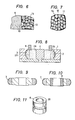
- Fig. 7 an iron-base powder compact is used as the core piece, and the infiltrant 12 forms a complete network which joins the iron and tungsten powder particles.
- the iron-base powder compact (non-infiltrated) is a Fe-2%Cu-0.8%C powder compact having 5.9 g/cm apparent density. If the apparent density of the powder compact is less than about 3.0 g/cm , the strength of the powder compact is too low. Moreover, if the apparent density of the powder compact is more than about 7.2 g/cm 3 , the interconnecting porosity of the compact is too small to permit sufficient infiltration. Thus, the apparent density of the iron-base powder compact should preferably be fixed within the above-mentioned range.
- each additive element thus preferably should be limited to the above-mentioned ranges. It is however possible to use molybdenum powder instead of tungsten powder.
- the welding strength between the inner surface of the infiltrated tungsten or like powder and the outer surface of the infiltrated iron-base powder compact can be remarkably increased.
- the whole construction is formed as an infiltrated powder compact which has high damping capabilities. Thus, no abnormal vibration during the use of the rotary dressers is observed.
- the core or inner bushing member is not dispensed with, but instead, the rotary dressers are produced in the following way: After setting super-abrasive grit such as diamond on the shaped surface of the negative mold and placing a core piece or bushing inside the told, an iron-base powder mixture and the tungsten-base powder mixture are concentrically filled in the space between the shaped surface and core piece or bushing. An infiltrant material such as Cu-Ni-Zn base alloy is then melted and infiltrated into the powder mixtures. The iron-base powder swells when Cu atoms dissolve into the iron during infiltration, compensating for the shrinkage of the tungsten metal powder during infiltration. Thus, the total dimensional change during infiltration becomes very small.
- a core piece 4 is placed in the negative mold 1.
- Metal powders such as a tungsten-base powder mixture 24 and iron-base powder mixture 28 are filled concentrically from the outer side in the space between the inner circular surface of negative mold 1 and the outer diameter of the core piece 4.
- a cylindrical separating wall 29 may be placed beforehand at the position of the border of the metal powder 24 and the iron-base powder mixture 28.
- the powder 24 is then filled in the space between the separating wall 29 and inner circular surfac-e of the negative mold 1, on which super-abrasive grit 5 have been set beforehand.
- the iron-base powder mixture 28 is then filled in the space between core piece 4 and separating wall 29, after which the wall 29 is pulled out.
- the composition of the iron-base powder mixture will be explained. hereinafter.
- Infiltrant 6 is placed on the concentric double layer of powder fillings, and the whole construction is heated to a temperature above the melting point of the infiltrant. After infiltration, the infiltrated body is machined in the same manner as a conventional rotary dresser. Thus, the rotary dresser shown in Fig. 9 is produced
- the core piece 4 is retained. If this core piece is replaced by a bushing, as illustrated in Fig. 4, and infiltration is performed, a rotary dresser having a bushing, as is shown in Fig. 10 is obtained.
- a rotary dresser having a bushing as is shown in Fig. 10 is obtained.
- an iron-base sintered compact, or an iron alloy body of, for example, stainless steel; having reverse tapered grooves 20 to prevent slip as shown in Fig. 11 is used as the bushing, the junction between the bushing 8 and the infiltrated body will be perfect.
- a tungsten powder filling of 8.8 g/cm 3 apparent density was placed-in contact with the test samples shown in Table 2, and an infiltrant composed mainly of Cu-Ni-Zn (890°C melting point) was put on the powder filling.
- the whole assembly was heated to 1030°C in a protective atmosphere.
- the infiltrant was melted and infiltrated to weld the infiltrated . tungsten body and the test samples. After cooling and solidification, the welding strength between the infiltrated tungsten powder and the test samples was measured:
- the iron-base powder mixture used in this invention Addition of 0.01-20% Cu is preferable because addition of less than 0.01% has little effect, whereas addition of more than 20% results in a decrease in strength. Addition of 0.01-4.5% C is preferable because the addition of 0.01% has little effect, whereas the addition of more than 4.5% results in an unfavourable decrease in strength because of the formation of a cast-iron structure.
- the iron-base powder mixture for the filling was an Fe-Cu-C three-element system.
- the welding strength between the tungsten-powder layer and iron-base powder layer increases remarkably because of the formation of a network of infiltrant material.
- the iron-base powder 8 enters into the grooves and the powder in the grooves swells when infiltrated.
- the grooves act as a strong prevention. against slippage.
- the infiltrated powder body prevents abnormal vibration because of its high damping capability.
- the infiltrated iron-base powder body is-lighter than infiltrated tungsten powder, so it is easier . to handle.
- the method described with reference to Figures 1 to 7 provides a method of producing a rotary dresser, comprising; providing an outer mold member including a super-abrasive material; placing an iron-base powder compact near the center of said mold member; filling a wear-resistant metallic powder mixture between said mold member and said compact; and heating the construction while melting an infiltrant thereinto, to form a sintered body bonded by said infiltrant and having said super-abrasive surface at the outside thereof.
- the method described with reference to Figures 8 to 11 provides a method of producing a rotary dresser, comprising; providing an outer mold member including a super-abrasive material; placing a core means near the center of said mold member; concentrically filling, from said mold member, a tungsten base powder mixture and an iron-base powder mixture between said mold member and said core means, placing an infiltrant on the assembly and heating the assembly to infiltrate said infiltrant into said powder mixtures,said infiltrant bonding said powder mixtures,to form a sintered body having said super-abrasive surface at the outside thereof.
Landscapes
- Engineering & Computer Science (AREA)
- Mechanical Engineering (AREA)
- Manufacturing & Machinery (AREA)
- Chemical & Material Sciences (AREA)
- Composite Materials (AREA)
- Materials Engineering (AREA)
- Polishing Bodies And Polishing Tools (AREA)
Applications Claiming Priority (4)
| Application Number | Priority Date | Filing Date | Title |
|---|---|---|---|
| JP15249381A JPS5856768A (ja) | 1981-09-25 | 1981-09-25 | ロ−タリドレツサ |
| JP152493/81 | 1981-09-25 | ||
| JP18290981A JPS5890465A (ja) | 1981-11-13 | 1981-11-13 | ロ−タリドレツサ |
| JP182909/81 | 1981-11-13 |
Publications (2)
| Publication Number | Publication Date |
|---|---|
| EP0075648A1 true EP0075648A1 (de) | 1983-04-06 |
| EP0075648B1 EP0075648B1 (de) | 1987-04-08 |
Family
ID=26481398
Family Applications (1)
| Application Number | Title | Priority Date | Filing Date |
|---|---|---|---|
| EP82104356A Expired EP0075648B1 (de) | 1981-09-25 | 1982-05-18 | Verfahren zur Herstellung eines Rundschleifkörpers |
Country Status (3)
| Country | Link |
|---|---|
| US (1) | US4456577A (de) |
| EP (1) | EP0075648B1 (de) |
| DE (1) | DE3275982D1 (de) |
Cited By (10)
| Publication number | Priority date | Publication date | Assignee | Title |
|---|---|---|---|---|
| EP0368783A1 (de) * | 1988-11-10 | 1990-05-16 | Lanxide Technology Company, Lp. | Verfahren zur Reproduktion der inversen Form von Verbundwerkstoff-Körpern mit Metallmatrix |
| EP0368784A1 (de) * | 1988-11-10 | 1990-05-16 | Lanxide Technology Company, Lp. | Verfahren zur Herstellung von Verbundwerkstoff-Körpern mit Metallmatrix durch freiwillige Infiltration |
| EP0369931A1 (de) * | 1988-11-10 | 1990-05-23 | Lanxide Technology Company, Lp. | Verfahren zum Formen von Makro-Verbundwerkstoff-Körpern und Makroprodukte daraus |
| EP0370940A1 (de) * | 1988-11-10 | 1990-05-30 | Lanxide Technology Company, Lp. | Verfahren zum Modifizieren der Eigenschaften eines Verbundwerkstoff-Körpers mit Metallmatrix |
| EP0375588A1 (de) * | 1988-11-10 | 1990-06-27 | Lanxide Technology Company, Lp. | Verfahren zur Herstellung von Verbundwerkstoff-Körpern mit Metallmatrix durch freiwillige Infiltration |
| US5518061A (en) * | 1988-11-10 | 1996-05-21 | Lanxide Technology Company, Lp | Method of modifying the properties of a metal matrix composite body |
| WO1998013159A1 (en) * | 1996-09-24 | 1998-04-02 | Baker Hughes Incorporated | Drill bit manufacturing method |
| US5848349A (en) * | 1993-06-25 | 1998-12-08 | Lanxide Technology Company, Lp | Method of modifying the properties of a metal matrix composite body |
| US6835349B2 (en) | 2001-08-29 | 2004-12-28 | The Dow Chemical Company | Boron containing ceramic-aluminum metal composite and method to form the composite |
| US20180304442A1 (en) * | 2015-12-18 | 2018-10-25 | Thyssenkrupp Ag | Grinding body having reduced weight |
Families Citing this family (2)
| Publication number | Priority date | Publication date | Assignee | Title |
|---|---|---|---|---|
| US4685607A (en) * | 1984-05-21 | 1987-08-11 | Kabushiki Kaisha Toshiba | Nitride ceramic-metal complex material and method of producing the same |
| US4787129A (en) * | 1984-07-06 | 1988-11-29 | Dresser Industries, Inc. | Metal of manufacturing a composite journal bushing |
Citations (5)
| Publication number | Priority date | Publication date | Assignee | Title |
|---|---|---|---|---|
| GB565520A (en) * | 1943-04-22 | 1944-11-14 | Cutanit | Improvements in the production of bodies formed of or comprising metal powder or powdered metallic compound |
| GB939392A (en) * | 1961-02-15 | 1963-10-16 | Norton Co | Hollow tool, e.g. a core drill, and method of making the same |
| GB1183845A (en) * | 1966-04-04 | 1970-03-11 | Renault | Improvements in or relating to the Production of Diamond Tools. |
| FR2222174A1 (de) * | 1973-03-20 | 1974-10-18 | Toyoda Machine Works Ltd | |
| WO1981003634A1 (en) * | 1980-06-11 | 1981-12-24 | Uddeholms Ab | Process of manufacturing sintered metallic compacts |
Family Cites Families (11)
| Publication number | Priority date | Publication date | Assignee | Title |
|---|---|---|---|---|
| US2145888A (en) * | 1936-06-06 | 1939-02-07 | American Optical Corp | Abrading tool |
| US2238382A (en) * | 1938-08-10 | 1941-04-15 | Gen Motors Corp | Formation of ferrous metal powders and formation of articles by sintering |
| US2401221A (en) * | 1943-06-24 | 1946-05-28 | Gen Motors Corp | Method of impregnating porous metal parts |
| GB632323A (en) * | 1946-04-23 | 1949-11-21 | American Electro Metal Corp | Producing by infiltration composite shaped bodies such as machine elements |
| US2753859A (en) * | 1952-03-07 | 1956-07-10 | Thompson Prod Inc | Valve seat insert |
| DE1458477B2 (de) * | 1964-05-15 | 1973-05-10 | Siemens AG, 1000 Berlin u. 8000 München | Verfahren zur herstellung eines durchdringungsverbundmetalls mit schichtweise verschiedener zusammensetzung fuer hochbelastbare elektrische kontakte |
| US3359623A (en) * | 1965-05-13 | 1967-12-26 | Talon Inc | Method for making refractory metal contacts having integral welding surfaces thereon |
| GB1264482A (de) * | 1969-02-03 | 1972-02-23 | ||
| US4008520A (en) * | 1970-02-07 | 1977-02-22 | Siemens Aktiengesellschaft | Contact member and method of manufacture |
| US3780418A (en) * | 1972-10-10 | 1973-12-25 | Aluminum Co Of America | Method of fabricating composite multi-metallic billets useful for metal working operations |
| US3889349A (en) * | 1973-06-08 | 1975-06-17 | Ford Motor Co | Brazing metal alloys |
-
1982
- 1982-05-11 US US06/376,992 patent/US4456577A/en not_active Expired - Fee Related
- 1982-05-18 EP EP82104356A patent/EP0075648B1/de not_active Expired
- 1982-05-18 DE DE8282104356T patent/DE3275982D1/de not_active Expired
Patent Citations (5)
| Publication number | Priority date | Publication date | Assignee | Title |
|---|---|---|---|---|
| GB565520A (en) * | 1943-04-22 | 1944-11-14 | Cutanit | Improvements in the production of bodies formed of or comprising metal powder or powdered metallic compound |
| GB939392A (en) * | 1961-02-15 | 1963-10-16 | Norton Co | Hollow tool, e.g. a core drill, and method of making the same |
| GB1183845A (en) * | 1966-04-04 | 1970-03-11 | Renault | Improvements in or relating to the Production of Diamond Tools. |
| FR2222174A1 (de) * | 1973-03-20 | 1974-10-18 | Toyoda Machine Works Ltd | |
| WO1981003634A1 (en) * | 1980-06-11 | 1981-12-24 | Uddeholms Ab | Process of manufacturing sintered metallic compacts |
Cited By (15)
| Publication number | Priority date | Publication date | Assignee | Title |
|---|---|---|---|---|
| CN1064289C (zh) * | 1988-11-10 | 2001-04-11 | 兰克西敦技术公司 | 制备大复合体的方法和由该方法生产的大复合体 |
| EP0368784A1 (de) * | 1988-11-10 | 1990-05-16 | Lanxide Technology Company, Lp. | Verfahren zur Herstellung von Verbundwerkstoff-Körpern mit Metallmatrix durch freiwillige Infiltration |
| EP0369931A1 (de) * | 1988-11-10 | 1990-05-23 | Lanxide Technology Company, Lp. | Verfahren zum Formen von Makro-Verbundwerkstoff-Körpern und Makroprodukte daraus |
| EP0370940A1 (de) * | 1988-11-10 | 1990-05-30 | Lanxide Technology Company, Lp. | Verfahren zum Modifizieren der Eigenschaften eines Verbundwerkstoff-Körpers mit Metallmatrix |
| EP0375588A1 (de) * | 1988-11-10 | 1990-06-27 | Lanxide Technology Company, Lp. | Verfahren zur Herstellung von Verbundwerkstoff-Körpern mit Metallmatrix durch freiwillige Infiltration |
| US5518061A (en) * | 1988-11-10 | 1996-05-21 | Lanxide Technology Company, Lp | Method of modifying the properties of a metal matrix composite body |
| EP0368783A1 (de) * | 1988-11-10 | 1990-05-16 | Lanxide Technology Company, Lp. | Verfahren zur Reproduktion der inversen Form von Verbundwerkstoff-Körpern mit Metallmatrix |
| CN1082554C (zh) * | 1988-11-10 | 2002-04-10 | 兰克西敦技术公司 | 改善金属基质复合体性能的方法 |
| US5848349A (en) * | 1993-06-25 | 1998-12-08 | Lanxide Technology Company, Lp | Method of modifying the properties of a metal matrix composite body |
| WO1998013159A1 (en) * | 1996-09-24 | 1998-04-02 | Baker Hughes Incorporated | Drill bit manufacturing method |
| US6089123A (en) * | 1996-09-24 | 2000-07-18 | Baker Hughes Incorporated | Structure for use in drilling a subterranean formation |
| US6073518A (en) * | 1996-09-24 | 2000-06-13 | Baker Hughes Incorporated | Bit manufacturing method |
| US6835349B2 (en) | 2001-08-29 | 2004-12-28 | The Dow Chemical Company | Boron containing ceramic-aluminum metal composite and method to form the composite |
| US7160627B2 (en) | 2001-08-29 | 2007-01-09 | The Dow Chemical Company | Boron containing ceramic-aluminum metal composite and method to form the composite |
| US20180304442A1 (en) * | 2015-12-18 | 2018-10-25 | Thyssenkrupp Ag | Grinding body having reduced weight |
Also Published As
| Publication number | Publication date |
|---|---|
| EP0075648B1 (de) | 1987-04-08 |
| DE3275982D1 (en) | 1987-05-14 |
| US4456577A (en) | 1984-06-26 |
Similar Documents
| Publication | Publication Date | Title |
|---|---|---|
| US8858870B2 (en) | Earth-boring bits and other parts including cemented carbide | |
| US3175260A (en) | Process for making metal carbide hard surfacing material and composite casting | |
| US5000273A (en) | Low melting point copper-manganese-zinc alloy for infiltration binder in matrix body rock drill bits | |
| US5051112A (en) | Hard facing | |
| US5096465A (en) | Diamond metal composite cutter and method for making same | |
| US5932508A (en) | Manufacture of a metal bonded abrasive product | |
| EP0374424B1 (de) | Mit Silizium infiltrierte poröse polykristalline Diamantkörper | |
| EP0075648B1 (de) | Verfahren zur Herstellung eines Rundschleifkörpers | |
| US2137201A (en) | Abrasive article and its manufacture | |
| US5505750A (en) | Infiltrant for metal bonded abrasive articles | |
| US3779726A (en) | A method of making a metal impregnated grinding tool | |
| Dwan | Production of diamond impregnated cutting tools | |
| IE52094B1 (en) | Steel-hard carbide macrostructured tools,compositions and methods of forming | |
| KR910001357B1 (ko) | 내마모층을 형성하는 방법 | |
| CA1336387C (en) | Rod for applying hard surfacing to a surface and method of making same | |
| EP0245440A1 (de) | Matrix aus wolframkarbid-kobalt-spänen und daraus hergestellter lagerwerkstoff. | |
| CA2070328A1 (en) | Composite diamond abrasive compact | |
| GB2157711A (en) | Improvements relating to tough material for tools and/or wearing parts | |
| JPH0243579B2 (de) | ||
| JPS60186374A (ja) | ダイヤモンド−金属鑞材含有複合体 | |
| CA1285776C (en) | High hardness sintered compact and process for producing the same | |
| JPS6146270B2 (de) | ||
| JPH0525935B2 (de) | ||
| JPH0140082B2 (de) | ||
| JPS6146269B2 (de) |
Legal Events
| Date | Code | Title | Description |
|---|---|---|---|
| PUAI | Public reference made under article 153(3) epc to a published international application that has entered the european phase |
Free format text: ORIGINAL CODE: 0009012 |
|
| 17P | Request for examination filed |
Effective date: 19820518 |
|
| AK | Designated contracting states |
Designated state(s): BE DE FR GB |
|
| GRAA | (expected) grant |
Free format text: ORIGINAL CODE: 0009210 |
|
| AK | Designated contracting states |
Kind code of ref document: B1 Designated state(s): BE DE FR GB |
|
| REF | Corresponds to: |
Ref document number: 3275982 Country of ref document: DE Date of ref document: 19870514 |
|
| ET | Fr: translation filed | ||
| PLBE | No opposition filed within time limit |
Free format text: ORIGINAL CODE: 0009261 |
|
| STAA | Information on the status of an ep patent application or granted ep patent |
Free format text: STATUS: NO OPPOSITION FILED WITHIN TIME LIMIT |
|
| 26N | No opposition filed | ||
| PG25 | Lapsed in a contracting state [announced via postgrant information from national office to epo] |
Ref country code: GB Effective date: 19890518 |
|
| PG25 | Lapsed in a contracting state [announced via postgrant information from national office to epo] |
Ref country code: BE Effective date: 19890531 |
|
| GBPC | Gb: european patent ceased through non-payment of renewal fee | ||
| PG25 | Lapsed in a contracting state [announced via postgrant information from national office to epo] |
Ref country code: FR Free format text: LAPSE BECAUSE OF NON-PAYMENT OF DUE FEES Effective date: 19900131 |
|
| PG25 | Lapsed in a contracting state [announced via postgrant information from national office to epo] |
Ref country code: DE Effective date: 19900201 |
|
| REG | Reference to a national code |
Ref country code: FR Ref legal event code: ST |