EP0075757A2 - Détecteur de fil de trame optique pour métier à tisser - Google Patents
Détecteur de fil de trame optique pour métier à tisser Download PDFInfo
- Publication number
- EP0075757A2 EP0075757A2 EP82108272A EP82108272A EP0075757A2 EP 0075757 A2 EP0075757 A2 EP 0075757A2 EP 82108272 A EP82108272 A EP 82108272A EP 82108272 A EP82108272 A EP 82108272A EP 0075757 A2 EP0075757 A2 EP 0075757A2
- Authority
- EP
- European Patent Office
- Prior art keywords
- weft
- reed
- light
- optical
- sensor
- Prior art date
- Legal status (The legal status is an assumption and is not a legal conclusion. Google has not performed a legal analysis and makes no representation as to the accuracy of the status listed.)
- Granted
Links
Images


Classifications
-
- D—TEXTILES; PAPER
- D03—WEAVING
- D03D—WOVEN FABRICS; METHODS OF WEAVING; LOOMS
- D03D51/00—Driving, starting, or stopping arrangements; Automatic stop motions
- D03D51/18—Automatic stop motions
- D03D51/34—Weft stop motions
Definitions
- the present invention relates generally to an optical weft sensor for a loom and more specifically to the installation position or installation method of an optical weft sensor for use with a fluid-jet loom.
- an optical weft sensor is provided for a fluid-jet room (air-jet loom or water-jet loom) in order to optically detect that a weft thread is securely inserted into fluid-guide plates having a fluid-guide opening and a weft-removing slot, respectively, and arranged in the direction of weft insertion.
- the optical weft sensor comprises a light-emitting section and a light-receiving section for detecting the presence or absence of weft depending upon the change in magnitude of the received light, which is caused when a weft removed through the weft-removing slot of the fluid-guide plate passes across an optical axis formed between the light-emitting section and the light-received section during the beat-up stage.
- an optical weft sensor for a fluid-jet loom such that it is possible to prevent the light-emitting and light-receiving elements from shock or vibration caused by the oscillating reed, to obtain a relatively long detection time period, to prevent the weft from being brought into contact with some part of the optical weft sensor, and to readily adjust the position of the weft sensor when the width of woven cloth is required to change.
- the light-emitting and light-receiving elements are disposed on an appropriate position of the loom frame and only the flexible optical fibers are arranged along the sley sword; the optical axis perpendicular to the end open surface of a bundle of the optical fibers is set so as to point at a position where the weft removed from the fluid-guide plates is in contact with the reed wires at at-least end stage of .
- the optical fibers are disposed out of a range within which the weft is relatively moved with respect to the reed at the beat-up stage; the sensor holder is fixed to the reed frame or the reed holder in such a way that the optical sensor can readily be adjusted along the longitudinal direction of the reed holder when the clcth width is required to change.
- the optical weft sensor for a loom comprises light emitting means, light receiving means, at least one light-emitting fiber and light-receiving fiber connected to the light emitting and receiving means optically, optical signal processing means for processing the received light to stop the loom in case a weft is not inserted into the shed, and sensor holding means for holding said optical fibers in such a direction that the optical axis thereof points at a position where the weft is in contact with the reed wires at the start or end stage of the weft beat-up motion.
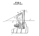
- Fig. 1 shows a prior-art optical sensor for use in an air-jet loom.
- the reference numeral 1 denotes a reed holder
- the reference numeral 2 denotes one of a plurality of air-guide plates having a series of . air-guide opening 3 and weft-removing slots 4.
- the reference numeral 5 denotes a reed.
- the reed holder 1, air-guide plates 2 and reed 5 oscillate together.
- the reference numeral 6 denotes a weft thread inserted into the air-guide opening 3
- the reference numeral 7 denotes warp threads
- the reference numeral 8 denotes a shed formed between the warp threads 7.
- Fig. 1 denotes a reed holder
- the reference numeral 2 denotes one of a plurality of air-guide plates having a series of . air-guide opening 3 and weft-removing slots 4.
- the reference numeral 5 denotes a
- an optical weft sensor comprises a light-emitting element 9 such as an LED mounted on the bottom of an air-guide plate, a light-receiving element 10 such as a phototransistor mounted near the weft-removing slot 4, and a light-transmitting element 11 such as an optical fiber attached to the air-guide plate 2.
- a light-emitting element 9 such as an LED mounted on the bottom of an air-guide plate
- a light-receiving element 10 such as a phototransistor mounted near the weft-removing slot 4
- a light-transmitting element 11 such as an optical fiber attached to the air-guide plate 2.
- the presence or absence of the weft 6 can be detected, when the weft 9 passes through the slot 4 at the beat-up stage and therefore the weft shuts out the light emitted from the light-emitting element 9 to the light-receiving element 10.
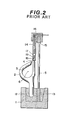
- Fig. 2 shows another prior-art optical sensor for use in an air-jet loom.
- the reed 5 is fixed to the reed holder 1 being sandwiched between an air-guide plate holder 12 and a wedge 13.
- the sensor section 14 is fixed to a reed frame 15 by the aid of a sensor holder 16.
- the sensor section 14 includes a sensor head 17 in which a light-emitting element and a light-receiving element are housed.
- the light emitted from the sensor head 17 is reflected from the weft 6, when the weft. passes through the slot 4 and near the open end surface 18 of a bundle of a plurality of optical fibers 19.
- the light reflected from the weft 6 is then received through the same open end 18 of a bundle of the optical fibers 19.
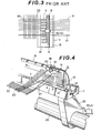
- Fig. 3 shows the top view of Fig. 2, in which the woven cloth 20 is illustrated together with a plurality of warp threads 7 and catch-cord yarns 21. Further, the reference numeral 22 denotes the cloth fell.
- the leno yarns and the catch-cord yarns are readily oscillated by the weft 6 vibrated by the sensor 14, there raises a problem in that wale streak is easily produced on the woven cloth side opposite to the weft picking side or the weft is not securely caught by the catch-cord yarns 21.
- a reed holder 1 is mounted on a sley sword 25 fixed to a sley sword shaft 26.
- the reed 5 is fixed to the reed holder 1 being sandwiched between an air-guide holder 12 and a wedge 13.
- a plurality of air-guide plates 2 having an air-guide opening 3 and a weft-removing slot 4 respectively are fixed by a bonding agent to the air-guide holder 12 being arranged in the weft direction.
- the reference numeral 6 denotes a weft
- the reference numeral 7 denotes a plurality of warp threads
- the reference numeral 21 denotes catch-cord yarns
- the reference numeral 20 denotes a woven cloth
- the reference numeral 22 denotes cloth fell.
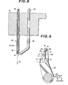
- a U-shaped optical weft sensor holder 16 is mounted on. top of a reed frame 15 and between the warp threads farmost from and opposite to the weft picking side and the catch-cord yarn 21 with a bolt 28 (shown in Fig. 5).
- optical fibers 30 connected optically to a light-emitting element such as a light-emitting diode and a light-receiving element such as a phototransistor is first fixed by a fixture 31 to the top portion of the reed frame 15 and then passed through a through hole formed in the sensor holder 16, being disposed near one of the reed wires 15' after having bent at an appropriate angle, the open end 18 of which faces downward and the optical axis OA of which is in parallel with the reed wires 15'.
- the light-emitting element such as a light-emitting diode 40 and the light-receiving element such as a phototransistor 41 are fixed within an appropriate circuit housing mounted on the loom frame.
- the fiber bundle 30 is arranged along the top portion of the reed frame 15 and along the sley sword 25 extending to near the center of the sley sword shaft 26. Therefore, when the reed 5 oscillates with the sley sword shaft 26 as its center, no shock or vibration is applied to the light-emitting diode 40 and the phototransistor 41. Further, since the optical fiber bundle 30 is separated from the sley sword 25 near its oscillating center, it is possible to minimize the oscillation stoke of the optical fiber bundle 30.
- Figs. 6 and 7 shows the structure of this light transmitting and receiving optical fibers 30 in more detail.
- a plurality of light-transmitting optical fibers 32 and light-receiving optical fibers 33 are collected into a single optical fiber bundle 30 as depicted in Fig. 7.
- the optical fiber bundle 30 is first passed through a resin collar 34 fitted to a hole of the sensor holder 16 and next passed through a metal pipe 35.
- the reference numeral 36 denotes an air nozzle connected to an air supply source (not shown) via an air pipe 37 in order to prevent fluff from sticking onto the open end surface 18 of the optical fiber bundle 30.
- a sensor light emitted from a light-emitting element (LED) 40 is transmitted through a plurality of light-emitting optical fibers 32 and emitted from the open end surface 18 of the bundle 30 of the optical fibers.
- the light reflected from the weft 6 is trnsmitted through a plurality of light-receiving optical fibers 33 and received by a light-receiving element (phototransistor) 41.
- the light signal indicative of the presence of weft received by the light-receiving element 41 is amplified and inverted via an inversion amplifier 42 in order to output a L-voltage level signal to one of two input terminals of an AND gate 43.
- a proximity switch 52 is connected the other of the two input terminals of the AND gate 43.
- This proximity switch 52 outputs a H-voltage level signal when a metal member 51 comes near to the. proximity switch 52.
- the metal member 51 is fixed to an arm 49 and rotates around a shaft 50 in synchronization with the movement of the loom.
- the proximity switch 52 is so designed as to output a H-voltage signal only while the reed wires are at the beat-up stage.
- the inversion amplifier 42 when the inversion amplifier 42 outputs a L-voltage level signal indicative of the presence of weft, even if the proximity switch 52 outputs a H-voltage level signal at the beat-up stage, no H-voltage - level signal is outputted from the AND gate 43.
- the inversion amplifier 42 when the inversion amplifier 42 outputs a H-voltage level signal indicative of the absence of weft, whenever the proximity switch 52 outputs a H-voltage level signal at the beat-up stage, a H-voltage level signal is outputted from the AND gate 43.
- the H-voltage level signal from the AND gate 43 is given to a monostable-multivibrator 44 in order to output a pulse signal with a sufficient pulse width.
- the pulse signal is then amplified via an amplifier 45, and given to a relay 46 in order to break a normally-closed contact 48, so that the loom is stopped in response to the H-voltage level signal from the AND gate 43, indicating the absence of weft 6.
- Figs. 10(A) to 10(C) show the mutual positions of the reed 5, air-guide plates 2, warp threads 7, weft 6, etc. Further, in the figure, the reference numeral 35 denotes a heald to give an opening movement to. the warp threads 7.
- the reed 5 moves frontward (leftward in Fig. 10) for performing beat-up motion.
- the weft is first removed through the weft-removing slot 4 of the air-guide plate 2 and is brought into contact with the reed wires 15' of the reed 5.
- the weft 6 is moved by the reed 5 and is beaten up to the cloth fell 22 as shown in Fig. 10(C).
- the light emitted from the optical fiber 30 is diffusion-reflected from the lower side of the reed 5 and is not received by the optical fiber bundle 30.
- the setup work (preparatory work for the loom) is simple without taking much time.
- the weft 6 removed through the slot 4 : of the air-guide plate 2 is not in contact with the optical fiber 30 or the sensor holder 16, the weft 6 is not vibrated by the optical sensor or the reed-5.
- an air nozzle 36 (shown in Fig. 6) is additionally provided for preventing fluff sticking onto the open end surface 18 of optical fiber bundle 30; however, if the open end surface 18 of the optical fiber bundle 30 is so fixed as to be brought into contact with the weft before the beat-up motion has been completed, it is possible to prevent fluff from sticking onto the open end surface 18 of the optical fiber bundle 30.
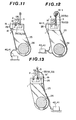
- Fig. 11 shows a second embodiment of the optical weft sensor according to the present invention.
- the sensor holder 16 is fixed to the front side surface of the reed holder 1 with a bolt 28.
- the projection portion 16' connected integrally to the sensor holder 16 is passed through between the two air-guide plates 2 extending along the top surface of the air-guide holder 12 and to near the reed wires.
- the bundle of light emitting and receiving optical fibers 30 is passed through a hole formed in the sensor holder 16 and the projection 16' being protected by a metal pipe 35, with the open end surface of the optical fiber bundle facing upward and with the optical axis OA preset in parallel with the reed wires.
- the light emitted from the light emitting fibers 32 is reflected from a weft which is in contact with the reed wires and is received by the light receiving fibers 33, so that the presence or absence of weft is detected.
- Fig. 12 shows a third embodiment of the optical weft sensor according to the present invention.
- the sensor holder 16 is divided into two holders 16-1 and 16-2.
- a bundle of light-emitting optical fibers 32 is held by the first sensor holder 16-1;
- a bundle of light-receiving optical fibers 33 is held by the second sensor holder 16-2.
- the sensor light is emitted from the upper fiber bundle 32 to the lower fiber bundle 33; however, it is of course possible to emit the sensor light from the lower fiber bundle 33 to the upper fiber bundle 32.
- the light-emitting element such as a light-emitting diode 40 and the light-receiving element such as a phototransistor 41 are fixed within an appropriate circuit housing mounted on the loom frame as in the first and the second embodiments.
- the light-emitting element such as a light-emitting diode 40 and the light-receiving element such as a phototransistor 41 are fixed within an appropriate circuit housing mounted on the loom frame as in the first and the second embodiments.
- two separate fiber bundles are arranged along different routes on and along the sley sword 25 extending to near the center of the sley sword shaft 26.
- Fig. 13 shows a fourth embodiment of the optical. weft sensor according to the present invention.
- the sensor holder 16 is fixed to the rear side surface of the reed holder 1 with a bolt 28.
- the projection portion 16' connected integrally with the sensor holder 16 is placed behind the reed 5 extending upward in parallel with the reed wires.
- the bundle 30 of light emitting and receiving optical fibers 32 and 33 is passed through the hole formed in the projection portion 16' being protected by a metal pipe 35, with the - open end surface of the optical fiber bundle facing frontward and with the optical axis OA preset roughly perpendicular to the reed wires.
- the light emitted from the light emitting fibers 32 is reflected from a weft and is received by the light receiving fibers 33, so that the presence or absence of weft can be detected.
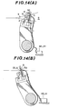
- Figs. 14(A) and 14(B) show the mutual positions of the reed 5, air-guide plate 2, warp threads 7, weft 6, etc. in the fourth embodiment.
- the reed 5 moves frontward (leftward in Fig. 4) for performing beat-up motion.
- the weft is first removed through the weft-removing slot 4 of the air-guide plate 2 and is brought into contact with the reed wires of the reed 5.
- the weft 6 is moved by the reed wires and is beaten up to the cloth fell 22 as shown in Fig. 14(B).
- the weft 6 is positioned near the open end surface of the optical sensor bundle 30 at the end stage of beat-up.motion; that is, positioned on the optical axis OA of the sensor while the weft 6 is in contact with the reed 5, the light emitted from the sensor open end surface is reflected from the weft 6 and is received through the sensor open end surface, so that the presence of the weft 6 can be detected.
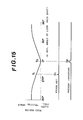
- Fig. 15 shows the relationships between sensor signal S 2 and the reed motion or the loom motion.
- the reed is being oscillated by the sley sword shaft with the shaft as its center, the speed of the reed becomes at its minimum (inflection points), that is, zero at the rearmost position (heald side) and the frontmost position (cloth fell side).
- the weft 6 is detected when being removed through the weft-removing slot, for instance, at the time t 1 in Fig. 15, the weft speed is relatively high and, therefore, the prior-art sensor signal s 1 is small with a short pulse width.
- the weft 6 is detected when the weft is in contact with the reed wires and beaten up to the cloth fell at the time T 2 (at the end stage of the beat-up motion) in Fig. 15, the weft speed is almost zero and, therefore, the detection time period is long and therefore the sensor signal S 2 is relatively large with a large pulse width, thus improving reliability in weft detection.
- the light emitting and receiving optical fibers are bundled into a single metal pipe, that is, a reflection-type optical weft sensor is described, it is of course possible to adopt a shut-out type optical weft sensor in which the light-emitting fibers are disposed on the rear side of the reed and the light-receiving fibers are disposed on the cloth fell side or vice versa.
- the setup work is simple without adjusting the air-guide plate position.
- Fig. 16 shows a fifth embodiment of the optical weft sensor according to the present invention.
- the sensor holder 16 is fixed to the front side surface of the reed holder 1 with a bolt 28.
- the projection portion 16' is passed through between the two air-guide plates 2 extending along the top surface of the air-guide holder 12 and to near the lower portion of one of the air-guide plates 2 and bending obliquely toward the weft-removing slot 4.
- the bundle of light emitting and receiving optical fibers is passed through the hole formed in the sensor holder (projection portion 16 1 ) being protected by a metal pipe 35, with the open end surface of the optical fiber bundle facing the weft-removing slot 4.
- the light emitted from the light emitting fibers is reflected from a weft when the weft passes through the slot 4 and is received by the light receiving fibers for detection of the presence or absence of weft.
- the optical sensor since the optical sensor is disposed at a position lower than the height of the weft-removing slot 4, the optical sensor will not interfere with the movement of the weft when the weft is removed through the slot 4.
- the setup work is simple without adjusting the air-guide plate position.
- Fig. 17 shows an sixth embodiment of the optical weft sensor according to the present invention.
- the sensor holder 16 is fixed to the front surface of the reed holder 1 with a bolt 28.
- the bundle 30 of light emitting and receiving optical fibers 32, 33 extends in the shape of a fourth part of a circle to near _ the weft-removing slot 4, with the open end surface of the optical fiber bundle facing horizontally.
- the light emitted from the light emitting fibers is reflected from the weft passing through the weft removing slot and is received by the light receiving fibers for detection of the presence or absence of weft.
- the optical sensor since the optical sensor is disposed near the weft-removing slot 4, the optical sensor will not interfere with the movement of the weft removed through the slot 4. Further, the sensor holder 16 can readily-be -adjusted to an appropriate position by removing only the bolt 28 and by sliding the holder 16 along the reed holder 1 to an appropriate position between the warp threads farmost from and opposite to the weft picking side and the catch-cord yarns, without adjusting the air-guide plates when the width of woven cloth is required to change.
- the optical weft sensor alway detects the weft from the front side without detecting the cloth fell or the preceding weft already beaten-up to the cloth fell, it is possible to determine the width of the timing signal outputted from the proximity switch to be large, thus improving the detection reliability.
- Fig. 18 shows a seventh embodiment of the optical weft sensor according to the present invention.
- the sensor holder 16 is fixed to the front surface of the reed holder 1 with a bolt 28.
- the projection portion 16 1 connected integrally with the sensor holder 16 is passed through between the two air-guide plates 2 extending along the top surface of the air-guide holder 12 and near to the reed wires and bending vertically to near the weft-removing slot 4 of one of the air-guide plates 2.
- the bundle 30 of light emitting and receiving optical fibers is passed through the hole formed in the sensor holders 16 and 16' being protected by a metal pipe, with the open end surface of the optical fiber bundle facing the weft-removing slot 4.
- the light emitted from the light emitting fibers is reflected from a weft passing through the weft-removing slot and is received by the light receiving fibers for detection of the presence or absence of weft.
- the optical sensor since the optical sensor is disposed at a position lower than the- height of the weft-removing slot 4, the optical sensor will not interfere with the movement of the weft removed through the slot 4. Further, the sensor holder 16 can readily be adjusted to an appropriate position by removing only the bolt 28 and by setting the holder 16 again to an appropriate position between the warp threads farmost from and opposite to the weft picking side and the catch-cord yarns, without adjusting the air-guide plates, when the width of woven cloth'is required to change.
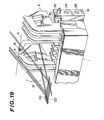
- Fig. 19 shows an eighth embodiment of the optical weft sensor according to the present invention.
- the sensor holder 16 is fixed to the side end surface of the reed holder 1 with two bolts 28, a L-shaped metal pipe 35 is passed through a hole formed in the sensor holder 16, and the metal pipe 35 is fixed by a screw 50.
- the metal pipe 35 extends between the air-guide plates 2 and the reed frame (not shown) and bends vertically to near the weft-removing slot 4 of one of the air-guide plates.
- the bundle of light emitting and receiving optical fibers is passed through the metal pipe 35, with the open end surface -18 of the optical fiber bundle facing the weft-removing slot 4.
- the light emitted from the light emitting fibers is reflected from a weft passing through the weft-removing slot and is received by the light-receiving fibers for detection of the presence or absence of weft.
- the optical sensor since the optical sensor is disposed at a position lower than the height of the weft-removing slot 4, the optical sensor will not interfere with the movement of the weft removed through the slot 4. Further, the open end surface 18 of the optical fiber bundle can readily be adjusted to an appropriate position - by loosening and fastening only the screw 50 when the width of woven cloth is required to change.
- This embodiment is convenient, in particular, when the gap between the air-guide plates is too small to dispose the sensor holder therebetween.
- the optical weft sensor for a loom since the sensor is supported by one or two sensor holders so as to be adjustable along the reed frame or the reed holder, since the optical axis is set to be near and in parallel with the reed wires or in the direction in which the weft moves from the weft removing slot to a position where the weft is in contact with the reed wires at the start stage of-the beat-up motion or toward a position where the weft is in contact with the reed wires at the end stage of the beat-up motion, since the weft sensor is arranged below or away from the weft-removing slot of the air-guide plate, and since the LED and the phototransistor are fixed on the loom frame without application of shock or vibration to these elements, it is possible to attain the following practical advantages:
Landscapes
- Engineering & Computer Science (AREA)
- Textile Engineering (AREA)
- Looms (AREA)
Applications Claiming Priority (8)
| Application Number | Priority Date | Filing Date | Title |
|---|---|---|---|
| JP15073681A JPS5854050A (ja) | 1981-09-25 | 1981-09-25 | 織機の緯糸検知装置 |
| JP150737/81 | 1981-09-25 | ||
| JP150736/81 | 1981-09-25 | ||
| JP15073781A JPS5854051A (ja) | 1981-09-25 | 1981-09-25 | 織機の緯糸検知装置 |
| JP171978/81U | 1981-11-20 | ||
| JP17197881U JPS5878993U (ja) | 1981-11-20 | 1981-11-20 | 空気噴射式織機の緯糸検知装置 |
| JP97560/82 | 1982-06-09 | ||
| JP9756082A JPS58214563A (ja) | 1982-06-09 | 1982-06-09 | 空気噴射式織機の緯糸検知装置 |
Publications (3)
| Publication Number | Publication Date |
|---|---|
| EP0075757A2 true EP0075757A2 (fr) | 1983-04-06 |
| EP0075757A3 EP0075757A3 (en) | 1983-08-24 |
| EP0075757B1 EP0075757B1 (fr) | 1986-01-02 |
Family
ID=27468553
Family Applications (1)
| Application Number | Title | Priority Date | Filing Date |
|---|---|---|---|
| EP82108272A Expired EP0075757B1 (fr) | 1981-09-25 | 1982-09-08 | Détecteur de fil de trame optique pour métier à tisser |
Country Status (4)
| Country | Link |
|---|---|
| US (1) | US4471816A (fr) |
| EP (1) | EP0075757B1 (fr) |
| KR (1) | KR850001118B1 (fr) |
| DE (1) | DE3268297D1 (fr) |
Cited By (3)
| Publication number | Priority date | Publication date | Assignee | Title |
|---|---|---|---|---|
| EP0189143A1 (fr) * | 1985-01-17 | 1986-07-30 | Nissan Motor Co., Ltd. | Système pour détecter la distribution de la vitesse d'écoulement |
| EP0344848A1 (fr) * | 1988-06-02 | 1989-12-06 | Picanol N.V. | Procédé d'enfilage de tuyères avec une longueur de fil de trame exacte et métier à tisser utilisant ce procédé |
| BE1019208A3 (fr) * | 2009-03-06 | 2012-04-03 | Toyota Jidoshokki Kk | Detecteur de trame pour un metier a tisser a jet. |
Families Citing this family (14)
| Publication number | Priority date | Publication date | Assignee | Title |
|---|---|---|---|---|
| SE453488B (sv) * | 1982-12-03 | 1988-02-08 | Trelleborg Ab | Tradvakt med ljusfangande organ forsedd med en skold |
| IT1171736B (it) * | 1983-10-10 | 1987-06-10 | Roy Electrotex Spa | Rilevatore ottico di trama per telai di tessitura a getto d'aria |
| US4598849A (en) * | 1984-03-23 | 1986-07-08 | Beloit Corporation | Web guiding and decurling apparatus |
| EP0204093B1 (fr) * | 1985-04-05 | 1989-08-02 | Kabushiki Kaisha Toyoda Jidoshokki Seisakusho | Méthode et dispositif pour détecter des fils de trame dans un métier automatique à fils de trame |
| US4870270A (en) * | 1988-02-26 | 1989-09-26 | Simmonds Precision Products, Inc. | Fiber optic speed sensing for a rotating shaft |
| US4999488A (en) * | 1990-01-29 | 1991-03-12 | Milliken Research Corporation | Method to continuously count the courses or picks of a moving fabric |
| JPH0482943A (ja) * | 1990-07-18 | 1992-03-16 | Tsudakoma Corp | 織機の緯糸フィーラ装置 |
| ATE356899T1 (de) * | 2001-06-09 | 2007-04-15 | Kloecker Gmbh Geb | Vorrichtung zur ermittlung von fadenbrüchen von dreherfäden bei webmaschinene bzw. webmaschine, insbesondere mit webschäften und einer vorrichtung zur ermittlung von fadenbrüchen |
| US7384586B2 (en) | 2004-03-23 | 2008-06-10 | 3M Innovative Properties Company | Method for flexing a web |
| US7399173B2 (en) * | 2004-03-23 | 2008-07-15 | 3M Innovative Properties Company | Apparatus for flexing a web |
| US8871298B2 (en) | 2006-02-08 | 2014-10-28 | 3M Innovative Properties Company | Method for manufacturing on a film substrate at a temperature above its glass transition |
| EP2089458B1 (fr) | 2006-09-28 | 2011-09-21 | 3M Innovative Properties Company | Procédé, système et et utilisation dudit système pour contrôler un roulage dans des bandes multicouches |
| US7998534B2 (en) | 2006-09-28 | 2011-08-16 | 3M Innovative Properties Company | System and method for controlling curl in multi-layer webs |
| JP5218340B2 (ja) * | 2009-08-27 | 2013-06-26 | 株式会社豊田自動織機 | ジェットルームにおける緯糸検出装置 |
Family Cites Families (14)
| Publication number | Priority date | Publication date | Assignee | Title |
|---|---|---|---|---|
| DE1710281A1 (de) * | 1967-02-10 | 1971-01-28 | Erhard Kenk | Schussfadenwaechter fuer Webmaschinen |
| DE1785035B2 (de) * | 1968-08-02 | 1973-01-11 | Sick, Erwin, 8000 München | Vorrichtung zur ueberwachung des schussfadens bei schuetzenlosen webstuehlen |
| CH485055A (de) * | 1968-12-16 | 1970-01-31 | Sulzer Ag | Gehäuse für optische Elemente |
| DE2105559A1 (en) * | 1971-02-06 | 1972-08-10 | Elitex Zawody textilniho strojirenstvi generalni rzeditelstvi, Reichenberg (Tschechoslowakei) | Weft thread detector - fitted to air jet shuttless looms |
| US3824401A (en) * | 1971-11-16 | 1974-07-16 | Enshu Seisaku Kk | Photoelectric type weft sensing process and weft sensor |
| NL7206368A (fr) * | 1972-05-10 | 1973-11-13 | ||
| US4085777A (en) * | 1973-07-24 | 1978-04-25 | Vyzkumny A Vyvojovy Ustav Zavodu Vseobecneho Strojirenstvi | Arrangement for the control of weft introduced into looms |
| US3978893A (en) * | 1974-09-26 | 1976-09-07 | Enshu, Limited | Apparatus for detecting success in weft insertion of shuttleless looms |
| JPS5328544B2 (fr) * | 1975-03-06 | 1978-08-15 | ||
| NL7602260A (en) * | 1975-03-06 | 1976-09-08 | Stop motion for loom operates when warp tension is reduced - compared with the tension during previous beating up operations | |
| JPS52155262A (en) * | 1976-06-17 | 1977-12-23 | Nissan Motor | Woof detector |
| JPS52155261A (en) * | 1976-06-17 | 1977-12-23 | Nissan Motor | Woof detector |
| US4384596A (en) * | 1981-01-07 | 1983-05-24 | Leesona Corporation | Means and method for sensing loom conditions indicative of potential fabric defects |
| GB2090619A (en) * | 1981-01-07 | 1982-07-14 | Leesona Corp | Means and method for sensing loom conditions |
-
1982
- 1982-09-08 DE DE8282108272T patent/DE3268297D1/de not_active Expired
- 1982-09-08 EP EP82108272A patent/EP0075757B1/fr not_active Expired
- 1982-09-21 US US06/420,844 patent/US4471816A/en not_active Expired - Fee Related
- 1982-09-22 KR KR828204278A patent/KR850001118B1/ko not_active Expired
Cited By (5)
| Publication number | Priority date | Publication date | Assignee | Title |
|---|---|---|---|---|
| EP0189143A1 (fr) * | 1985-01-17 | 1986-07-30 | Nissan Motor Co., Ltd. | Système pour détecter la distribution de la vitesse d'écoulement |
| EP0344848A1 (fr) * | 1988-06-02 | 1989-12-06 | Picanol N.V. | Procédé d'enfilage de tuyères avec une longueur de fil de trame exacte et métier à tisser utilisant ce procédé |
| BE1001718A3 (nl) * | 1988-06-02 | 1990-02-13 | Picanol Nv | Werkwijze voor het aanbrengen van een juiste lengte inslagdraad in straalmondstukken van weefmachines en weefmachine die deze werkwijze toepast. |
| US4967807A (en) * | 1988-06-02 | 1990-11-06 | Picanol N.V. | System for threading loom jet nozzle with correct length of the weft thread |
| BE1019208A3 (fr) * | 2009-03-06 | 2012-04-03 | Toyota Jidoshokki Kk | Detecteur de trame pour un metier a tisser a jet. |
Also Published As
| Publication number | Publication date |
|---|---|
| US4471816A (en) | 1984-09-18 |
| KR840001655A (ko) | 1984-05-16 |
| KR850001118B1 (ko) | 1985-08-03 |
| EP0075757B1 (fr) | 1986-01-02 |
| DE3268297D1 (en) | 1986-02-13 |
| EP0075757A3 (en) | 1983-08-24 |
Similar Documents
| Publication | Publication Date | Title |
|---|---|---|
| US4471816A (en) | Optical weft sensor for a loom | |
| US4738284A (en) | Method and an apparatus for detecting the weft yarn in a jet loom | |
| KR100432266B1 (ko) | 파워 직조기 내의 씨실 삽입 최적화 및 감시 방법 | |
| US4976292A (en) | Weft end tensioning and detecting devices for shuttleless loom | |
| US3608590A (en) | Optical weft stop motion for a weaving machine | |
| US4295499A (en) | Detection of weft in shuttleless loom | |
| JP3238799U (ja) | 織機における緯糸不足検出用の光学機器 | |
| US4415008A (en) | Device for monitoring the weft thread travel on an air jet weaving machine | |
| EP0290706B1 (fr) | Dispositif de contrôle du fil de trame dans les métiers à tisser à jet d'air | |
| CN1227398C (zh) | 纬线监测装置 | |
| KR100446361B1 (ko) | 직물 방적사의 주행/정지 상태를 모니터하는 방법 | |
| CN109974834B (zh) | 喷气式织机的筘振动量检测方法 | |
| US4962794A (en) | Air jet loom with integral stretch pipe and pick sensor | |
| JPH0571046A (ja) | 流体噴射式織機における緯糸検知装置 | |
| US4221242A (en) | Optical filling or weft bobbin feeler | |
| JPS6141351A (ja) | 空気噴射式織機の緯糸端部処理装置 | |
| Kabir | Exploration of the advancement in warp & weft stop motion: primitive to electronic system | |
| SU1652398A1 (ru) | Подающа рапира дл прокладывани петли уточной нити к бесчелночному ткацкому станку | |
| SU1564227A1 (ru) | Устройство дл контрол нити на бесчелночном ткацком станке | |
| JPS62206065A (ja) | ウオ−タジエツトル−ムの緯糸検知装置 | |
| JPS59199843A (ja) | 空気噴射式織機の緯糸検知装置 | |
| JPH0321656B2 (fr) | ||
| JPS61252343A (ja) | ジエツトル−ムにおける緯糸検出方法 | |
| JPH0262621B2 (fr) | ||
| CS272964B1 (en) | Pickup of weft threadrange especially for jet weaving looms |
Legal Events
| Date | Code | Title | Description |
|---|---|---|---|
| PUAI | Public reference made under article 153(3) epc to a published international application that has entered the european phase |
Free format text: ORIGINAL CODE: 0009012 |
|
| 17P | Request for examination filed |
Effective date: 19820908 |
|
| AK | Designated contracting states |
Designated state(s): CH DE FR GB IT LI |
|
| PUAL | Search report despatched |
Free format text: ORIGINAL CODE: 0009013 |
|
| AK | Designated contracting states |
Designated state(s): CH DE FR GB IT LI |
|
| RAP1 | Party data changed (applicant data changed or rights of an application transferred) |
Owner name: NISSAN MOTOR CO., LTD. |
|
| ITF | It: translation for a ep patent filed | ||
| GRAA | (expected) grant |
Free format text: ORIGINAL CODE: 0009210 |
|
| AK | Designated contracting states |
Designated state(s): CH DE FR GB IT LI |
|
| REF | Corresponds to: |
Ref document number: 3268297 Country of ref document: DE Date of ref document: 19860213 |
|
| ET | Fr: translation filed | ||
| PG25 | Lapsed in a contracting state [announced via postgrant information from national office to epo] |
Ref country code: LI Effective date: 19860930 Ref country code: CH Effective date: 19860930 |
|
| PLBE | No opposition filed within time limit |
Free format text: ORIGINAL CODE: 0009261 |
|
| STAA | Information on the status of an ep patent application or granted ep patent |
Free format text: STATUS: NO OPPOSITION FILED WITHIN TIME LIMIT |
|
| 26N | No opposition filed | ||
| PG25 | Lapsed in a contracting state [announced via postgrant information from national office to epo] |
Ref country code: FR Free format text: LAPSE BECAUSE OF NON-PAYMENT OF DUE FEES Effective date: 19870527 |
|
| REG | Reference to a national code |
Ref country code: CH Ref legal event code: PL |
|
| PG25 | Lapsed in a contracting state [announced via postgrant information from national office to epo] |
Ref country code: DE Effective date: 19870602 |
|
| GBPC | Gb: european patent ceased through non-payment of renewal fee | ||
| REG | Reference to a national code |
Ref country code: FR Ref legal event code: ST |
|
| PG25 | Lapsed in a contracting state [announced via postgrant information from national office to epo] |
Ref country code: GB Effective date: 19881121 |