EP0076033A1 - Innenzahnradpumpe mit regelbarer Liefermenge - Google Patents
Innenzahnradpumpe mit regelbarer Liefermenge Download PDFInfo
- Publication number
- EP0076033A1 EP0076033A1 EP82304423A EP82304423A EP0076033A1 EP 0076033 A1 EP0076033 A1 EP 0076033A1 EP 82304423 A EP82304423 A EP 82304423A EP 82304423 A EP82304423 A EP 82304423A EP 0076033 A1 EP0076033 A1 EP 0076033A1
- Authority
- EP
- European Patent Office
- Prior art keywords
- annuli
- pump
- rings
- rotor
- meshed
- Prior art date
- Legal status (The legal status is an assumption and is not a legal conclusion. Google has not performed a legal analysis and makes no representation as to the accuracy of the status listed.)
- Withdrawn
Links
Images


Classifications
-
- F—MECHANICAL ENGINEERING; LIGHTING; HEATING; WEAPONS; BLASTING
- F04—POSITIVE - DISPLACEMENT MACHINES FOR LIQUIDS; PUMPS FOR LIQUIDS OR ELASTIC FLUIDS
- F04C—ROTARY-PISTON, OR OSCILLATING-PISTON, POSITIVE-DISPLACEMENT MACHINES FOR LIQUIDS; ROTARY-PISTON, OR OSCILLATING-PISTON, POSITIVE-DISPLACEMENT PUMPS
- F04C14/00—Control of, monitoring of, or safety arrangements for, machines, pumps or pumping installations
- F04C14/10—Control of, monitoring of, or safety arrangements for, machines, pumps or pumping installations characterised by changing the positions of the inlet or outlet openings with respect to the working chamber
-
- F—MECHANICAL ENGINEERING; LIGHTING; HEATING; WEAPONS; BLASTING
- F04—POSITIVE - DISPLACEMENT MACHINES FOR LIQUIDS; PUMPS FOR LIQUIDS OR ELASTIC FLUIDS
- F04C—ROTARY-PISTON, OR OSCILLATING-PISTON, POSITIVE-DISPLACEMENT MACHINES FOR LIQUIDS; ROTARY-PISTON, OR OSCILLATING-PISTON, POSITIVE-DISPLACEMENT PUMPS
- F04C2/00—Rotary-piston machines or pumps
- F04C2/08—Rotary-piston machines or pumps of intermeshing-engagement type, i.e. with engagement of co-operating members similar to that of toothed gearing
- F04C2/10—Rotary-piston machines or pumps of intermeshing-engagement type, i.e. with engagement of co-operating members similar to that of toothed gearing of internal-axis type with the outer member having more teeth or tooth-equivalents, e.g. rollers, than the inner member
- F04C2/102—Rotary-piston machines or pumps of intermeshing-engagement type, i.e. with engagement of co-operating members similar to that of toothed gearing of internal-axis type with the outer member having more teeth or tooth-equivalents, e.g. rollers, than the inner member the two members rotating simultaneously around their respective axes
Definitions
- This invention relates to oil purps for internal combustion engines.
- the output requirement from an oil pump is maximum when the engine is at maximum speed/load. It is customary to design an oil pump to deliver the required lubricant flow under such conditions, and then when the engine is idling, the pump output is probably too great, and the surplus lubricant is returned to the oil sump by means of some vent, presure relief valve or the like. Inevitably this means that the pump wastes energy.
- the object of the present invention is to provide such an oil pump.
- a gerotor pump of the n and n+1 kind comprises a rotor common to at least a pair of axially juxtaposed annuli, and the annuli being located in individual and corresponding eccentric mounting rings, and means being provided for turning said rings in opposite directions whereby the effective size of the pumping chambers provided between the respective lobes of the rotor and annuli may be varied.
- the pumping chambers will be of a maximum effective size.
- one of the rings is turned relative to the other, for exarple by making it in the fashion of a known reversing ring and turning it to the reversed position, a maximum size chamber between the one annulus and the rotor will be aligned with a minimum size chamber between the other annulus and the rotor. This not only reduces the volume of the chamber, but because the reverse situation will apply at a different points around the gyratory path, it will mean that the pulping effect will be substantially reduced.
- a series of chambers exist between the respective lobes, and these chambers increase in volume from a minimum to a maximum and then return to that minimum as the parts turn.
- the inlet and outlet ports are located so that oil is drawn in by the increasing volume of the chambers and expelled by the decreasing volume of the chambers. If the ports were not appropriately situated, reducing volume of the chambers will not be associated with an outlet port and because the oil is effectively incompressible, the trapped cil in the chamber causes the noise referred tc.
- annuli are to be turned to equal distances in opposite directions, and some variation can be obtained by appropriate length of inlet and outlet ports, and some degree of entrapment is acceptable.
- variable volume oil pump for an i.e. engine has the two rings coupled together for movement in opposite directions. This may be done automatically and proportionally (within limits) to engine speed and load, and one way of achieving this, for example, is by the use of governor devices, in a manner analogous to that employed with automatic advance/retard mechanisms for i.e. ignition systems.
- FIG. 1 the gerotor pump is there illustrated with a cover, normally held in place by screws engaged in holes 10, removed to reveal the rotors and pumping chambers.
- the inner rotor 12 has n lobes and is fast with drive shaft 14.
- the rotor 12 extends ever the full width of two annuli 16 18 which are like, and each has n+1 lobes.
- Each of the rotors 16 18 is eccentric to the shaft 14 axis, and lies in a corresponding eccentric ring 20 22. When the eccentric rings are aligned then annuli 16 18 are aligned and an end elevation will appear as in Figure 2.
- the eccentric rings 20 22 are provided with gear teeth and both sets of teeth are meshed with a common pinion 24, and when that pinion is rotated about its axis, the two eccentric rings are turned in opposite directions and hence shift the respective positions of the annuli 16 18.
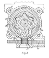
- Figure 3 shows the parts in a shifted position.
- the pinion 24 is arranged to be rotated, in this embodiment, by a rack 30 which may be driven by pressure derived from any of a number of different places in the pump or in the engine (for exanple) to which the pump is fitted.
- the pinion is preferably urged by a torsion spring so that when pressure falls the pinion automatically reverses its direction and returns the annuli towards the aligned position.
- Figure 1 illustrates an arrangement in which pressure in the outlet port of the pump itself is connected via passage 32 and by way of a filter to act on piston 34 for displacing the rack 30. If a comparatively external pressure source is to be utilised, the passage 32 may be blocked.
Landscapes
- Engineering & Computer Science (AREA)
- Mechanical Engineering (AREA)
- General Engineering & Computer Science (AREA)
- Rotary Pumps (AREA)
- Details And Applications Of Rotary Liquid Pumps (AREA)
Applications Claiming Priority (2)
| Application Number | Priority Date | Filing Date | Title |
|---|---|---|---|
| GB8126680 | 1981-09-03 | ||
| GB8126680 | 1981-09-03 |
Publications (1)
| Publication Number | Publication Date |
|---|---|
| EP0076033A1 true EP0076033A1 (de) | 1983-04-06 |
Family
ID=10524289
Family Applications (1)
| Application Number | Title | Priority Date | Filing Date |
|---|---|---|---|
| EP82304423A Withdrawn EP0076033A1 (de) | 1981-09-03 | 1982-08-20 | Innenzahnradpumpe mit regelbarer Liefermenge |
Country Status (1)
| Country | Link |
|---|---|
| EP (1) | EP0076033A1 (de) |
Cited By (7)
| Publication number | Priority date | Publication date | Assignee | Title |
|---|---|---|---|---|
| EP0174734A3 (de) * | 1984-09-08 | 1986-12-30 | Concentric Pumps Limited | Ölpumpe |
| GB2192669A (en) * | 1986-07-07 | 1988-01-20 | Concentric Pumps Ltd | Oil pump |
| GB2204096A (en) * | 1987-03-20 | 1988-11-02 | Concentric Pumps Ltd | Variable output oil pump |
| US5544540A (en) * | 1994-12-29 | 1996-08-13 | Dana Corporation | Gerotor pump for vehicle transmission lubrication system |
| WO2003095840A1 (en) * | 2002-05-10 | 2003-11-20 | Pierburg S.P.A. | Variable-delivery rotary pump, in particular for oil |
| US7278841B2 (en) * | 2001-12-13 | 2007-10-09 | Performance Pumps, Llc | Gerotor pump |
| EP2708748A1 (de) * | 2012-09-12 | 2014-03-19 | Schwäbische Hüttenwerke Automotive GmbH | Umschaltpumpe mit beidseitiger Befüllung und/oder Entleerung |
Citations (5)
| Publication number | Priority date | Publication date | Assignee | Title |
|---|---|---|---|---|
| GB628084A (en) * | 1946-09-05 | 1949-08-22 | Vickers Inc | Improvements in rotary pumps and motors |
| FR1171379A (fr) * | 1957-01-07 | 1959-01-26 | Perfectionnements apportés aux machines à engrenages conjugués | |
| GB896393A (en) * | 1959-08-14 | 1962-05-16 | Robert Wesley Brundage | Variable volume internal chamber type hydraulic pump |
| DE1231563B (de) * | 1963-01-16 | 1966-12-29 | Danfoss As | Regelbare Zahnradpumpe |
| GB1426223A (en) * | 1973-05-15 | 1976-02-25 | Concentric Pumps Ltd | Rotary positive-idsplacement pumps |
-
1982
- 1982-08-20 EP EP82304423A patent/EP0076033A1/de not_active Withdrawn
Patent Citations (5)
| Publication number | Priority date | Publication date | Assignee | Title |
|---|---|---|---|---|
| GB628084A (en) * | 1946-09-05 | 1949-08-22 | Vickers Inc | Improvements in rotary pumps and motors |
| FR1171379A (fr) * | 1957-01-07 | 1959-01-26 | Perfectionnements apportés aux machines à engrenages conjugués | |
| GB896393A (en) * | 1959-08-14 | 1962-05-16 | Robert Wesley Brundage | Variable volume internal chamber type hydraulic pump |
| DE1231563B (de) * | 1963-01-16 | 1966-12-29 | Danfoss As | Regelbare Zahnradpumpe |
| GB1426223A (en) * | 1973-05-15 | 1976-02-25 | Concentric Pumps Ltd | Rotary positive-idsplacement pumps |
Cited By (12)
| Publication number | Priority date | Publication date | Assignee | Title |
|---|---|---|---|---|
| EP0174734A3 (de) * | 1984-09-08 | 1986-12-30 | Concentric Pumps Limited | Ölpumpe |
| GB2192669A (en) * | 1986-07-07 | 1988-01-20 | Concentric Pumps Ltd | Oil pump |
| US4778361A (en) * | 1986-07-07 | 1988-10-18 | Concentric Pumps Limited | Variable output gerotor pump |
| GB2192669B (en) * | 1986-07-07 | 1990-01-31 | Concentric Pumps Ltd | Oil pump |
| GB2204096A (en) * | 1987-03-20 | 1988-11-02 | Concentric Pumps Ltd | Variable output oil pump |
| EP0284226A3 (en) * | 1987-03-20 | 1989-05-24 | Concentric Pumps Limited | Variable output oil pump |
| US4887956A (en) * | 1987-03-20 | 1989-12-19 | Concentric Pumps Limited | Variable output oil pump |
| GB2204096B (en) * | 1987-03-20 | 1991-02-06 | Concentric Pumps Ltd | Variable output oil pump |
| US5544540A (en) * | 1994-12-29 | 1996-08-13 | Dana Corporation | Gerotor pump for vehicle transmission lubrication system |
| US7278841B2 (en) * | 2001-12-13 | 2007-10-09 | Performance Pumps, Llc | Gerotor pump |
| WO2003095840A1 (en) * | 2002-05-10 | 2003-11-20 | Pierburg S.P.A. | Variable-delivery rotary pump, in particular for oil |
| EP2708748A1 (de) * | 2012-09-12 | 2014-03-19 | Schwäbische Hüttenwerke Automotive GmbH | Umschaltpumpe mit beidseitiger Befüllung und/oder Entleerung |
Similar Documents
| Publication | Publication Date | Title |
|---|---|---|
| CA2159672C (en) | A valve train with suction-controlled ring gear/internal gear pump | |
| US5152264A (en) | Internal combustion engine oil pump with cover | |
| EP0079156A1 (de) | Ölpumpe | |
| US3447472A (en) | Gearing and lubricating means therefor | |
| JPH05263770A (ja) | オイルポンプ | |
| EP0076033A1 (de) | Innenzahnradpumpe mit regelbarer Liefermenge | |
| US4887956A (en) | Variable output oil pump | |
| US4373483A (en) | Lubricating oil pump drive for an internal combustion engine | |
| EP0565340B1 (de) | Innenzahnradpumpe mit regelbarer Liefermenge | |
| US4486160A (en) | Pumps and motors | |
| US5685266A (en) | Ring gear pumps | |
| EP1087139B1 (de) | Innenzahnradpumpe | |
| EP0660000A1 (de) | Verdrängungspumpen | |
| JP3350633B2 (ja) | ギヤ駆動式のオイルポンプ | |
| AU8102591A (en) | Improvements in gerotor pumps | |
| US3298315A (en) | Series connected pumping system | |
| JPS61152980A (ja) | 吐出量可変式歯車ポンプ | |
| EP0486164B1 (de) | Gerotorpumpen | |
| KR200212882Y1 (ko) | 오일펌프의 기어구조 | |
| GB1149124A (en) | Differential gear assemblies | |
| RU1807238C (ru) | Шестеренный насос | |
| Wilson | Oil pumps | |
| JPH07102928A (ja) | オイルポンプの構造 | |
| JP2651243B2 (ja) | ディーゼル機関における燃料噴射ポンプの回転駆動装置 | |
| JP2022117255A (ja) | オイルポンプ |
Legal Events
| Date | Code | Title | Description |
|---|---|---|---|
| PUAI | Public reference made under article 153(3) epc to a published international application that has entered the european phase |
Free format text: ORIGINAL CODE: 0009012 |
|
| AK | Designated contracting states |
Designated state(s): AT DE FR GB IT NL SE |
|
| STAA | Information on the status of an ep patent application or granted ep patent |
Free format text: STATUS: THE APPLICATION IS DEEMED TO BE WITHDRAWN |
|
| 18D | Application deemed to be withdrawn |
Effective date: 19840305 |
|
| RIN1 | Information on inventor provided before grant (corrected) |
Inventor name: CHILD, ROBIN EDWARD |