EP0076111B1 - Kupplungs- und Bremssystem zum Starten und Stoppen einer Leistungspresse - Google Patents
Kupplungs- und Bremssystem zum Starten und Stoppen einer Leistungspresse Download PDFInfo
- Publication number
- EP0076111B1 EP0076111B1 EP82305042A EP82305042A EP0076111B1 EP 0076111 B1 EP0076111 B1 EP 0076111B1 EP 82305042 A EP82305042 A EP 82305042A EP 82305042 A EP82305042 A EP 82305042A EP 0076111 B1 EP0076111 B1 EP 0076111B1
- Authority
- EP
- European Patent Office
- Prior art keywords
- brake
- clutch
- press
- drive shaft
- hydraulic
- Prior art date
- Legal status (The legal status is an assumption and is not a legal conclusion. Google has not performed a legal analysis and makes no representation as to the accuracy of the status listed.)
- Expired
Links
- 230000007246 mechanism Effects 0.000 claims description 30
- 238000000034 method Methods 0.000 claims description 13
- 230000004044 response Effects 0.000 claims description 11
- 230000008878 coupling Effects 0.000 claims description 6
- 238000010168 coupling process Methods 0.000 claims description 6
- 238000005859 coupling reaction Methods 0.000 claims description 6
- 230000001351 cycling effect Effects 0.000 claims description 4
- 230000003100 immobilizing effect Effects 0.000 claims 2
- 230000001133 acceleration Effects 0.000 description 7
- 125000006850 spacer group Chemical group 0.000 description 3
- 230000007704 transition Effects 0.000 description 3
- 238000013459 approach Methods 0.000 description 2
- 230000008901 benefit Effects 0.000 description 2
- 239000012634 fragment Substances 0.000 description 2
- 230000007257 malfunction Effects 0.000 description 2
- 230000009471 action Effects 0.000 description 1
- 238000003491 array Methods 0.000 description 1
- 230000013011 mating Effects 0.000 description 1
- 238000012986 modification Methods 0.000 description 1
- 230000004048 modification Effects 0.000 description 1
- 230000009467 reduction Effects 0.000 description 1
- 230000035939 shock Effects 0.000 description 1
Images


Classifications
-
- B—PERFORMING OPERATIONS; TRANSPORTING
- B30—PRESSES
- B30B—PRESSES IN GENERAL
- B30B15/00—Details of, or accessories for, presses; Auxiliary measures in connection with pressing
- B30B15/10—Brakes specially adapted for presses
-
- B—PERFORMING OPERATIONS; TRANSPORTING
- B30—PRESSES
- B30B—PRESSES IN GENERAL
- B30B15/00—Details of, or accessories for, presses; Auxiliary measures in connection with pressing
- B30B15/12—Clutches specially adapted for presses
-
- B—PERFORMING OPERATIONS; TRANSPORTING
- B30—PRESSES
- B30B—PRESSES IN GENERAL
- B30B15/00—Details of, or accessories for, presses; Auxiliary measures in connection with pressing
- B30B15/14—Control arrangements for mechanically-driven presses
- B30B15/142—Control arrangements for mechanically-driven presses controlling the brake or the clutch
Definitions
- the present invention relates generally to power presses and, more particularly, to an improved clutching and braking system for starting and stopping a power press.
- the abrupt transitions produced by the pneumatic system described above can disrupt the automation system and cause damage to the workpieces or even to the press.
- the automation system must be programmed to provide excessive clearances between the various controlled mechanisms, which reduces the productivity of the press system.
- G.B. 804 482 It is known from G.B. 804 482 that a reduction in violent engagement shocks can be achieved by the use of a hydraulically operated clutch for connecting and disconnecting the press drive and the slide mechanism and by arranging for the machine to be started with a relatively low initial coupling torque provided by a correspondingly low initial hydraulic pressure.
- the hydraulic pressure is raised to a second, higher value corresponding to the application of full torque.
- the clutch is released and the brake is applied simultaneously at its full brake torque level.
- a method of starting and stopping a power press having a slide mechanism mounted for reciprocating movement, a press drive for cycling the slide mechanism, a hydraulic clutch for connecting and disconnecting the press drive and the slide mechanism and adapted to be operated at intermediate and full torque levels by means of two different hydraulic pressures, and a hydraulic brake for braking the press drive shaft, said method being characterised by:
- the invention also provides an apparatus for starting and stopping a power press having a slide mechanism mounted for reciprocating movement, a press drive for cycling the slide mechanism, a hydraulic clutch for connecting and disconnecting the press drive and the slide mechanism and adapted to be operated at intermediate and full torque levels by means of two different hydraulic pressures, and a hydraulic brake for braking the press drive shaft, said apparatus being characterised by:
- One advantage of such an improved starting and stopping system is that it permits increases in the productivity of an automated press system having automatically controlled workpiece handling mechanisms.
- Another advantage of such an improved system for starting and stopping a power press is that it minimizes the danger of damage to, and prolongs the operating life of, those portions of the press involved in, or controlled by, the automation system.
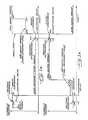
- the brake torque immediately drops to zero at time t11, and the clutch torque immediately increases to an intermediate torque level determined by one of two sources of hydraulic pressure for the clutch.
- the intermediate torque level is typically about 10% of full clutch torque.
- the clutch is maintained at this intermediate torque level for a preselected time interval, extending from time t11 to time t12 in Fig. 1 b, which is sufficient to bring the press drive shaft up to full speed.
- the hydraulic pressure on the clutch is increased to immediately raise the clutch torque to its full-on level, which is determined by the source of hydraulic pressure for the clutch.
- a tachometer can be used to monitor the actual speed of the press drive shaft and detect when it reaches full speed.
- the tachometer output can be used to produce a signal which automatically connects the full-on pressure source to the clutch as soon as the drive shaft reaches full speed.
- the clutch torque After the clutch torque has been increased to its full-on level at time t12, it is maintained at this level until it is desired to stop the press. Stopping is initiated by de-energizing a solenoid at time t13 to actuate a valve that applies hydraulic pressure to the brake and removes hydraulic pressure from the clutch. Following another brief “electrical delay” from time t13 to time t14, this immediately disengages the clutch and engages the brake (at time t14).
- the brake torque is initially limited, however, to an intermediate torque level, e.g., 40% in the example of Fig. 1a, until the press drive shaft has been substantially stopped at time t15.
- the full hydraulic pressure is applied to the brake to produce full brake torque.
- the brake is then maintained at this full torque level until it is desired to start the press again.
- the two different torque levels for the hydraulic brake are determined by two sources of hydraulic pressure for the brake.
- the brake is connected to the first source, which sets the intermediate torque level, from time t14 to time t15, and then is switched to the second source, which sets the full-on torque level.
- the hydraulic brake can be applied with immediately full brake torque at time t14, as illustrated by the broken lines in Fig. 1a.
- This "panic stop" mode of operation illustrated by the broken lines is undesirable because of the high rate of deceleration that it produces, but it will stop the press very quickly in an emergency.
- FIG. 2 and 3 there is shown a hydraulically operated brake for applying a braking torque to a press drive shaft 10.
- a brake disc 11 is affixed to a hub 12 on the end of the shaft 10, and a plurality of brake pads 13 are carried by the disc 11 and arranged in a symmetrical array around the circumference of the disc.
- a movable gripper ring 14 is advanced into engagement with one side of the brake pads 13 to press the pads against a stationary gripper ring 15 fastened to the press frame 16.
- a multiplicity of radial ribs 15a are formed on the outside of the ring 15.
- the movable gripper ring 14 is advanced into its engagement position by means of hydraulic pressure supplied through a line 20 to a piston 21 slidably mounted in a primary cylinder plate 22.
- the hydraulic pressure moves the piston 21 to the left, as viewed in Fig. 3, thereby advancing a pressure plate 23 which is rigidly connected to the movable gripper ring 14 by means of a plurality of bolts 24 and spacers 25.
- the hydraulic pressure is simply removed from the line 20.
- the two cylinder plates 22 and 34 are connected by a plurality of machine screws 36 passing through corresponding spacers 37, which in turn pass through the fixed part 32.
- the two cylinder plates 22 and 34 are linked together in a rigid assembly which can be moved back and forth relative to the fixed plate 32 which is disposed between the two cylinder plates to provide a stationary support for one end of the springs 30 and 31.
- the hydraulic pressure from the line 32 will drop off, because the line 32 is connected to the same pressure source as the primary actuator line 20.
- the springs 30 and 31 move the two cylinder plates 22 and 34 to the left (as viewed in Fig. 3) thereby advancing the movable gripper ring 14 into engagement with the friction pads 13 to apply the brake. Consequently, the brake fails in a safe mode, automatically braking the press drive shaft in the event of a malfunction in the hydraulic system.
- a hydraulically operated clutch for use in conjunction with the hydraulic brake of Figs. 2 and 3, is shown in Figs. 4 and 5.
- the clutch is used to connect and disconnect the press drive shaft 10 and a flywheel 40 through a clutch disc 41 affixed to a hub 42 on the drive shaft.
- a plurality of friction pads 43 are carried by the disc 41 in a symmetrical array around the circumference of the disc.
- a movable gripper ring 44 is advanced into engagement with one side of the friction pads 43 to press the pads against a stationary gripper ring 45 fastened to the flywheel 40.
- a multiplicity of fins 45a are formed on the outside of the ring 45.
- the movable gripper ring 44 is advanced into its engaged position by means of hydraulic pressure supplied through a line 46 and a rotary coupling 47 to a piston 48 slidably mounted in a cylinder plate 49.
- the hydraulic pressure moves the piston 48 to the left, as viewed in Fig. 5, thereby advancing a pressure plate 50 which is rigidly connected to the movable gripper ring 44 by means of a spacer ring 51.
- the hydraulic pressure is simply removed from the line 46.
Landscapes
- Engineering & Computer Science (AREA)
- Mechanical Engineering (AREA)
- Control Of Presses (AREA)
- Braking Arrangements (AREA)
Claims (18)
Applications Claiming Priority (2)
| Application Number | Priority Date | Filing Date | Title |
|---|---|---|---|
| US305839 | 1981-09-28 | ||
| US06/305,839 US4446785A (en) | 1981-09-28 | 1981-09-28 | Hydraulic clutching and braking system for starting and stopping a power press |
Publications (3)
| Publication Number | Publication Date |
|---|---|
| EP0076111A2 EP0076111A2 (de) | 1983-04-06 |
| EP0076111A3 EP0076111A3 (en) | 1984-06-06 |
| EP0076111B1 true EP0076111B1 (de) | 1987-08-12 |
Family
ID=23182586
Family Applications (1)
| Application Number | Title | Priority Date | Filing Date |
|---|---|---|---|
| EP82305042A Expired EP0076111B1 (de) | 1981-09-28 | 1982-09-24 | Kupplungs- und Bremssystem zum Starten und Stoppen einer Leistungspresse |
Country Status (10)
| Country | Link |
|---|---|
| US (1) | US4446785A (de) |
| EP (1) | EP0076111B1 (de) |
| JP (1) | JPS5868499A (de) |
| KR (1) | KR880000612B1 (de) |
| AR (1) | AR229057A1 (de) |
| AU (1) | AU8833082A (de) |
| BR (1) | BR8205641A (de) |
| CA (1) | CA1195175A (de) |
| DE (1) | DE3276933D1 (de) |
| ES (1) | ES516011A0 (de) |
Families Citing this family (5)
| Publication number | Priority date | Publication date | Assignee | Title |
|---|---|---|---|---|
| ES2102289B1 (es) * | 1992-12-02 | 1998-01-16 | Coop Goizper S | Freno-embrague neumatico mejorado. |
| US6006660A (en) * | 1998-08-12 | 1999-12-28 | The Minster Machine Company | Segmented drive disk for a mechanical press |
| JP2010158718A (ja) * | 2008-12-08 | 2010-07-22 | Sumitomo Heavy Industries Techno-Fort Co Ltd | 湿式クラッチブレーキの油圧制御装置 |
| JP5091928B2 (ja) * | 2009-08-10 | 2012-12-05 | 住友重機械テクノフォート株式会社 | 機械プレスのクラッチブレーキ制御装置 |
| DE202014007305U1 (de) | 2014-09-08 | 2015-01-09 | Siempelkamp Maschinen- Und Anlagenbau Gmbh | Spindelpresse |
Family Cites Families (14)
| Publication number | Priority date | Publication date | Assignee | Title |
|---|---|---|---|---|
| DE717082C (de) * | 1939-07-28 | 1942-02-05 | Miag Muehlenbau Und Ind Ag | Hydraulisch gesteuerte Bremsekupplung |
| US2436968A (en) * | 1945-07-31 | 1948-03-02 | Cleveland Punch & Shear Works | Combined clutch and brake |
| US2577641A (en) * | 1950-05-05 | 1951-12-04 | Minster Machine Co | Multiple drive press with multiple clutch |
| US2905290A (en) * | 1954-05-25 | 1959-09-22 | Niagara Machine & Tool Works | Clutch brake sequence control for power presses and the like |
| US2838150A (en) * | 1954-10-29 | 1958-06-10 | Ind Clutch Corp | Interconnected clutch and brake mechanism |
| GB804482A (en) * | 1955-12-05 | 1958-11-19 | Eumuco Ag Fur Maschb | An improved torque transmission device for use in presses and other workshop machinery |
| US3000478A (en) * | 1959-07-16 | 1961-09-19 | Ferracute Machine Company | Clutch-brake mechanism |
| US3224538A (en) * | 1963-06-20 | 1965-12-21 | William E Ward | Clutch unit for power press |
| DE1502319A1 (de) * | 1965-01-05 | 1969-04-10 | Schuler Gmbh L | Pressenkupplung |
| US3371759A (en) * | 1967-02-07 | 1968-03-05 | Bliss E W Co | Clutch control for mechanical devices |
| US3580371A (en) * | 1969-10-16 | 1971-05-25 | King Of Prussia Research & Dev | Self-synchronizing clutch |
| DE2412195A1 (de) * | 1974-03-14 | 1975-09-18 | Ortlinghaus Werke Gmbh | Hydraulisch schaltbare kupplungsbremsvorrichtung |
| GB1491203A (en) * | 1974-10-21 | 1977-11-09 | Volvo Ab | Devices for limiting torsional shocks |
| JPS5434952A (en) * | 1977-08-23 | 1979-03-14 | Redei Kk | Shoes making method |
-
1981
- 1981-09-28 US US06/305,839 patent/US4446785A/en not_active Expired - Fee Related
-
1982
- 1982-09-01 CA CA000410599A patent/CA1195175A/en not_active Expired
- 1982-09-13 AU AU88330/82A patent/AU8833082A/en not_active Abandoned
- 1982-09-15 KR KR8204186A patent/KR880000612B1/ko not_active Expired
- 1982-09-24 DE DE8282305042T patent/DE3276933D1/de not_active Expired
- 1982-09-24 EP EP82305042A patent/EP0076111B1/de not_active Expired
- 1982-09-27 BR BR8205641A patent/BR8205641A/pt not_active IP Right Cessation
- 1982-09-28 ES ES516011A patent/ES516011A0/es active Granted
- 1982-09-28 AR AR290797A patent/AR229057A1/es active
- 1982-09-28 JP JP57169462A patent/JPS5868499A/ja active Pending
Also Published As
| Publication number | Publication date |
|---|---|
| JPS5868499A (ja) | 1983-04-23 |
| EP0076111A2 (de) | 1983-04-06 |
| CA1195175A (en) | 1985-10-15 |
| DE3276933D1 (en) | 1987-09-17 |
| BR8205641A (pt) | 1983-08-30 |
| ES8403380A1 (es) | 1984-03-16 |
| AR229057A1 (es) | 1983-05-31 |
| EP0076111A3 (en) | 1984-06-06 |
| ES516011A0 (es) | 1984-03-16 |
| KR880000612B1 (ko) | 1988-04-18 |
| AU8833082A (en) | 1983-04-14 |
| KR840001477A (ko) | 1984-05-07 |
| US4446785A (en) | 1984-05-08 |
Similar Documents
| Publication | Publication Date | Title |
|---|---|---|
| EP0076111B1 (de) | Kupplungs- und Bremssystem zum Starten und Stoppen einer Leistungspresse | |
| US4108295A (en) | Inertia-brake control for input shaft of gear box, and its application to clutches and units formed by a clutch and a gear-box | |
| EP0040027B1 (de) | Scheibenbremsen | |
| EP0110637B1 (de) | Scheibenbremsen für Fahrzeuge | |
| US4030577A (en) | Negative disc brake with a clearance-takeup mechanism | |
| US5452779A (en) | Dual piston hydraulic cylinder for clutch and upshift brake actuator | |
| EP0130137A1 (de) | Betätigungs- und Nachstellvorrichtung für Scheibenbremse | |
| EP0848790B1 (de) | Pressantrieb mit kupplungs-bremsantrieb mit hydraulischer scherung | |
| EP1122455B1 (de) | Nasslaufende Scheibenbremse mit vermindertem Strömungswiderstand | |
| KR100284445B1 (ko) | 구동 유니트용 전환장치 | |
| US2890773A (en) | Clutch-brake mechanism | |
| US3039440A (en) | Valve for press clutch | |
| CA1038308A (en) | Fail-safe disc brake | |
| CN110979642B (zh) | 电刹车装置的释放机构及其使用方法 | |
| GB2075623A (en) | Disc brakes | |
| CN211167393U (zh) | 一种电刹车装置的释放机构 | |
| US3096855A (en) | Disk brake | |
| US4461371A (en) | Brake actuator device with automatic slack adjuster | |
| US2864481A (en) | Clutch with adjusting means | |
| US3092228A (en) | Power presses and other similar machine tools | |
| US2773567A (en) | Disc brake actuating mechanism | |
| EP4722556A1 (de) | Bremsanordnung für ein schienenfahrzeug | |
| EP0056779B1 (de) | Parkbremse | |
| CA1152007A (en) | Self-adjusting brake engine limit switch assembly | |
| JP2010131657A (ja) | サーボプレスの非常停止方法およびサーボプレス |
Legal Events
| Date | Code | Title | Description |
|---|---|---|---|
| PUAI | Public reference made under article 153(3) epc to a published international application that has entered the european phase |
Free format text: ORIGINAL CODE: 0009012 |
|
| AK | Designated contracting states |
Designated state(s): DE FR GB IT |
|
| PUAL | Search report despatched |
Free format text: ORIGINAL CODE: 0009013 |
|
| AK | Designated contracting states |
Designated state(s): DE FR GB IT |
|
| 17P | Request for examination filed |
Effective date: 19841122 |
|
| GRAA | (expected) grant |
Free format text: ORIGINAL CODE: 0009210 |
|
| AK | Designated contracting states |
Kind code of ref document: B1 Designated state(s): DE FR GB IT |
|
| REF | Corresponds to: |
Ref document number: 3276933 Country of ref document: DE Date of ref document: 19870917 |
|
| ITF | It: translation for a ep patent filed | ||
| ET | Fr: translation filed | ||
| PLBE | No opposition filed within time limit |
Free format text: ORIGINAL CODE: 0009261 |
|
| STAA | Information on the status of an ep patent application or granted ep patent |
Free format text: STATUS: NO OPPOSITION FILED WITHIN TIME LIMIT |
|
| ITPR | It: changes in ownership of a european patent |
Owner name: CESSIONE;AVONDALE INDUSTRIES INC. |
|
| ITPR | It: changes in ownership of a european patent |
Owner name: CESSIONE;CONNELL INDUSTRIES INC. |
|
| 26N | No opposition filed | ||
| REG | Reference to a national code |
Ref country code: FR Ref legal event code: TP |
|
| PGFP | Annual fee paid to national office [announced via postgrant information from national office to epo] |
Ref country code: GB Payment date: 19900803 Year of fee payment: 9 |
|
| PGFP | Annual fee paid to national office [announced via postgrant information from national office to epo] |
Ref country code: FR Payment date: 19900919 Year of fee payment: 9 |
|
| ITTA | It: last paid annual fee | ||
| PGFP | Annual fee paid to national office [announced via postgrant information from national office to epo] |
Ref country code: DE Payment date: 19901031 Year of fee payment: 9 |
|
| PG25 | Lapsed in a contracting state [announced via postgrant information from national office to epo] |
Ref country code: GB Effective date: 19910924 |
|
| GBPC | Gb: european patent ceased through non-payment of renewal fee | ||
| PG25 | Lapsed in a contracting state [announced via postgrant information from national office to epo] |
Ref country code: FR Effective date: 19920529 |
|
| PG25 | Lapsed in a contracting state [announced via postgrant information from national office to epo] |
Ref country code: DE Effective date: 19920602 |
|
| REG | Reference to a national code |
Ref country code: FR Ref legal event code: ST |
|
| ITPR | It: changes in ownership of a european patent |
Owner name: CESSIONE;DANLY - KOMATSU L.P. |