EP0076201A1 - Kernreaktorbrennelement und Verfahren zu dessen Herstellung - Google Patents
Kernreaktorbrennelement und Verfahren zu dessen Herstellung Download PDFInfo
- Publication number
- EP0076201A1 EP0076201A1 EP82401706A EP82401706A EP0076201A1 EP 0076201 A1 EP0076201 A1 EP 0076201A1 EP 82401706 A EP82401706 A EP 82401706A EP 82401706 A EP82401706 A EP 82401706A EP 0076201 A1 EP0076201 A1 EP 0076201A1
- Authority
- EP
- European Patent Office
- Prior art keywords
- sheath
- column
- fertile
- spacer
- plug
- Prior art date
- Legal status (The legal status is an assumption and is not a legal conclusion. Google has not performed a legal analysis and makes no representation as to the accuracy of the status listed.)
- Granted
Links
Images

Classifications
-
- G—PHYSICS
- G21—NUCLEAR PHYSICS; NUCLEAR ENGINEERING
- G21C—NUCLEAR REACTORS
- G21C3/00—Reactor fuel elements and their assemblies; Selection of substances for use as reactor fuel elements
- G21C3/02—Fuel elements
- G21C3/04—Constructional details
- G21C3/16—Details of the construction within the casing
- G21C3/18—Internal spacers or other non-active material within the casing, e.g. compensating for expansion of fuel rods or for compensating excess reactivity
-
- G—PHYSICS
- G21—NUCLEAR PHYSICS; NUCLEAR ENGINEERING
- G21C—NUCLEAR REACTORS
- G21C3/00—Reactor fuel elements and their assemblies; Selection of substances for use as reactor fuel elements
- G21C3/02—Fuel elements
- G21C3/04—Constructional details
- G21C3/16—Details of the construction within the casing
-
- Y—GENERAL TAGGING OF NEW TECHNOLOGICAL DEVELOPMENTS; GENERAL TAGGING OF CROSS-SECTIONAL TECHNOLOGIES SPANNING OVER SEVERAL SECTIONS OF THE IPC; TECHNICAL SUBJECTS COVERED BY FORMER USPC CROSS-REFERENCE ART COLLECTIONS [XRACs] AND DIGESTS
- Y02—TECHNOLOGIES OR APPLICATIONS FOR MITIGATION OR ADAPTATION AGAINST CLIMATE CHANGE
- Y02E—REDUCTION OF GREENHOUSE GAS [GHG] EMISSIONS, RELATED TO ENERGY GENERATION, TRANSMISSION OR DISTRIBUTION
- Y02E30/00—Energy generation of nuclear origin
- Y02E30/30—Nuclear fission reactors
-
- Y—GENERAL TAGGING OF NEW TECHNOLOGICAL DEVELOPMENTS; GENERAL TAGGING OF CROSS-SECTIONAL TECHNOLOGIES SPANNING OVER SEVERAL SECTIONS OF THE IPC; TECHNICAL SUBJECTS COVERED BY FORMER USPC CROSS-REFERENCE ART COLLECTIONS [XRACs] AND DIGESTS
- Y10—TECHNICAL SUBJECTS COVERED BY FORMER USPC
- Y10T—TECHNICAL SUBJECTS COVERED BY FORMER US CLASSIFICATION
- Y10T29/00—Metal working
- Y10T29/49—Method of mechanical manufacture
- Y10T29/49764—Method of mechanical manufacture with testing or indicating
- Y10T29/49778—Method of mechanical manufacture with testing or indicating with aligning, guiding, or instruction
- Y10T29/4978—Assisting assembly or disassembly
-
- Y—GENERAL TAGGING OF NEW TECHNOLOGICAL DEVELOPMENTS; GENERAL TAGGING OF CROSS-SECTIONAL TECHNOLOGIES SPANNING OVER SEVERAL SECTIONS OF THE IPC; TECHNICAL SUBJECTS COVERED BY FORMER USPC CROSS-REFERENCE ART COLLECTIONS [XRACs] AND DIGESTS
- Y10—TECHNICAL SUBJECTS COVERED BY FORMER USPC
- Y10T—TECHNICAL SUBJECTS COVERED BY FORMER US CLASSIFICATION
- Y10T29/00—Metal working
- Y10T29/49—Method of mechanical manufacture
- Y10T29/49826—Assembling or joining
- Y10T29/49861—Sizing mating parts during final positional association
-
- Y—GENERAL TAGGING OF NEW TECHNOLOGICAL DEVELOPMENTS; GENERAL TAGGING OF CROSS-SECTIONAL TECHNOLOGIES SPANNING OVER SEVERAL SECTIONS OF THE IPC; TECHNICAL SUBJECTS COVERED BY FORMER USPC CROSS-REFERENCE ART COLLECTIONS [XRACs] AND DIGESTS
- Y10—TECHNICAL SUBJECTS COVERED BY FORMER USPC
- Y10T—TECHNICAL SUBJECTS COVERED BY FORMER US CLASSIFICATION
- Y10T29/00—Metal working
- Y10T29/49—Method of mechanical manufacture
- Y10T29/49826—Assembling or joining
- Y10T29/49908—Joining by deforming
- Y10T29/49925—Inward deformation of aperture or hollow body wall
- Y10T29/49927—Hollow body is axially joined cup or tube
- Y10T29/49929—Joined to rod
Definitions
- the invention relates to a combustible or fertile needle of a nuclear reactor. It also relates to a process for manufacturing these needles.
- the fuel needles of a fast neutron nuclear reactor generally consist of a metal sheath inside of which there are fissile and fertile pellets, while the fertile fuel needles consist of a sheath inside of which there are only a column of fertile pastilles.
- this column is maintained using a retaining ring with a diameter slightly greater than that of the sheath and having a longitudinal slot which is force-fitted at the desired level inside the sheath.
- French patents No. 2,018,665, No. 2,051,797 and No. 1,429,797 describe devices of this type.
- the subject of the invention is a combustible or fertile nuclear reactor needle and a simple method for manufacturing these needles, which makes it possible to reduce the manufacturing costs.
- the invention relates to a combustible needle and a fertile nuclear reactor needle of the type which includes a sheath, a column of fissile and / or fertile pellets inside the sheath, and welded end caps. at both ends of the sheath. It is characterized in that the column of pellets is maintained for the two types of needles by two tubular spacers of small thickness and with rounded edges placed in abutment against the two ends of the column and crimped at a fixed dimension on the sheath; and for the combustible needle, by an additional crimp for positioning the fertile column.
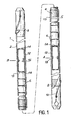
- the combustible needle shown in FIG. 1, designated by the general reference 1, is constituted by a metallic sheath 2 with a thin wall, the length of which is very large compared to its diameter. Inside the sheath 2 are stacked pellets of fissile and fertile fuel 6. At its two ends, the sheath is closed by a plug 8 welded to the sheath. A wire 10 wound in a spiral around the sheath 2 ensures the spacing of the combustible needles of the same assembly.
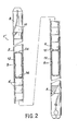
- the needle 1 'shown in Figure 2 is a fertile needle. Like the combustible needle of FIG. 1, it is constituted by a metallic sheath 2 with a thin wall. However, unlike the latter, it only contains fertile pastilles 6. At its two ends, it is closed by a plug 8 welded to the sheath 2.
- the pellets are held at the two ends by tubular spacers 12 and by an additional crimp for positioning the fertile column, for the combustible needle.
- the spacers 12 are rounded at their ends as shown in Figure 3 to form a planar support surface for the pellets.
- the holes 14 which remain on the surfaces 13 allow the passage of the gases released by the fission reaction which occurs during the operation of the nuclear reactor.
- the spacers 12 are placed in abutment respectively above and below the column of pellets and they are crimped with the sheath 2. This crimping is carried out from the outside, for example by isostatic or mechanical deformation (knurling). Thus, the spacers 12 are blocked in translation relative to the sheath. This ensures the maintenance of the column of fissile and / or fertile pellets.
- the combustible or fertile needle produced in accordance with the invention safely supports the stresses due to the differential expansions occurring in particular during the first ramp-up of the nuclear reactor. In steady state, these needles have a behavior identical to that of the needles of the prior art in which the column is maintained by a spring device.
- spacers 12 such as that shown in FIG. 4.
- This spacer shown in perspective, com carries a number of notches 16, made longitudinally at the two ends in the wall of the tube. These indentations leave in relief tongues 18 which are deformable under the effect of the thrust resulting from the expansion of the column of pellets. The deformation of the tongues 18 limits the force transmitted to the sheath.
- the invention also relates to a process for manufacturing the combustible or fertile needles which have just been described.
- This process has two variants depending on the type of needle. It is known in fact that the core of a fast neutron nuclear reactor consists essentially of combustible and fertile assemblies containing respectively a bundle of combustible needles and a bundle of fertile needles.
- the fuel needles have in their central part a column of fissile pellets and, above and below this column of fissile pellets, an upper axial cover and a lower axial cover of fertile pellets. Fertile needles only contain fertile lozenges. The manufacture of these two types of needles is different since the fertile needles do not contain plutonium.
- the sheath is crimped at a dimension C located near the upper end of the column of fertile pellets 6 forming the lower axial cover of the needle in order to keep this column in a fixed position (see FIG. 1).
- the purpose of this crimping is to position the fertile pastilles 6.
- the fertile pastilles 6 are introduced through the lower end of the sheath 2.
- a lower spacer 12 is introduced in contact with the fertile column and the sheath is crimped with the spacer at the fixed dimension A.
- the length of the spacer 12 is sufficient so that it is always possible to crimp it with the sheath at this fixed dimension A relative to the sheath, taking into account the variations in length of the fertile column coming from the manufacturing tolerances of the pellets.
- the fissi pellets are introduced through the upper part of the sheath 2 4. Introduce above the fissile column upper fertile pellets 6 and then the upper spacer 12 in contact with the fertile column. The sheath and the spacer are crimped at the fixed dimension B. As already mentioned with regard to the lower spacer 12, the height of the upper spacer 12 allows the tolerances on the total height of the stack of pellets.
- the upper plug is introduced 8. It is welded and the welding is checked.
- the process of the invention also applies to the manufacture of fertile needles.
- the needle has only one type of pastilles and it is no longer necessary to crimp the sheath at the fixed dimension C.
- all of the operations can be carried out outside a controlled area . The realization is therefore facilitated.
- the first part of manufacturing can be carried out outside the enclosure and in air.
- the assembly can start either from the bottom or the top of the needle.
- a spacer 12 is introduced, this spacer and the sheath are crimped to a fixed first dimension A or B.
- the upper or lower plug is introduced depending on the side on which the spacer has been introduced and crimped.
- the plug is welded and the welding of this plug is checked.
- the fertile pellets are introduced, then a second spacer in contact with the fertile fuel column, and this spacer is crimped to a second fixed dimension B or A.
- the end of manufacture is carried out by connecting the open end of the needle to a vacuum installation in order to evacuate the residual air contained in the needle. We then establish an at mosphere controlled inside the enclosure, by
- the second plug 8 is placed, it is welded and the welding of this second plug is checked.
Landscapes
- Physics & Mathematics (AREA)
- Engineering & Computer Science (AREA)
- Plasma & Fusion (AREA)
- General Engineering & Computer Science (AREA)
- High Energy & Nuclear Physics (AREA)
- Monitoring And Testing Of Nuclear Reactors (AREA)
- Silicates, Zeolites, And Molecular Sieves (AREA)
- Butt Welding And Welding Of Specific Article (AREA)
Applications Claiming Priority (2)
| Application Number | Priority Date | Filing Date | Title |
|---|---|---|---|
| FR8118414 | 1981-09-30 | ||
| FR8118414A FR2513796B1 (fr) | 1981-09-30 | 1981-09-30 | Aiguille combustible et fertile pour reacteur nucleaire et son procede de fabrication |
Publications (2)
| Publication Number | Publication Date |
|---|---|
| EP0076201A1 true EP0076201A1 (de) | 1983-04-06 |
| EP0076201B1 EP0076201B1 (de) | 1986-07-09 |
Family
ID=9262613
Family Applications (1)
| Application Number | Title | Priority Date | Filing Date |
|---|---|---|---|
| EP82401706A Expired EP0076201B1 (de) | 1981-09-30 | 1982-09-21 | Kernreaktorbrennelement und Verfahren zu dessen Herstellung |
Country Status (5)
| Country | Link |
|---|---|
| US (1) | US4678924A (de) |
| EP (1) | EP0076201B1 (de) |
| JP (1) | JPS5868693A (de) |
| DE (1) | DE3271944D1 (de) |
| FR (1) | FR2513796B1 (de) |
Cited By (4)
| Publication number | Priority date | Publication date | Assignee | Title |
|---|---|---|---|---|
| EP0308707A1 (de) * | 1987-09-15 | 1989-03-29 | Siemens Aktiengesellschaft | Brennstab für ein Kernreaktor-Brennelement |
| EP0364910A3 (en) * | 1988-10-20 | 1990-08-29 | Abb Reaktor Gmbh | Control rod for influencing the reactivity of a nuclear reactor, and arrangement of a plurality of these control rods as a control element |
| FR2920585A1 (fr) * | 2007-08-27 | 2009-03-06 | Korea Nuclear Fuel Co Ltd | Barre de combustible d'un ensemble de combustible nucleaire ayant un ressort de compression semblable a un vase concu pour augmenter le volume interne de celui-ci |
| EP2065896A1 (de) * | 2007-11-28 | 2009-06-03 | GE-Hitachi Nuclear Energy Americas LLC | Kernbrennstab mit eingeschlossenem Abstandhalterelement und Verfahren zur Nutzung desselben |
Families Citing this family (6)
| Publication number | Priority date | Publication date | Assignee | Title |
|---|---|---|---|---|
| SE506818C2 (sv) * | 1996-06-20 | 1998-02-16 | Asea Atom Ab | Kärnbränslepatron |
| SE508645C2 (sv) * | 1996-06-20 | 1998-10-26 | Asea Atom Ab | Kärnbränslepatron för lättvattenreaktor med axiellt gap i det klyvbara materialet |
| DE29800282U1 (de) * | 1998-01-13 | 1998-06-10 | Siemens AG, 80333 München | Versandbereites Kernreaktor-Brennelement |
| US6370214B1 (en) * | 1999-07-08 | 2002-04-09 | Framtome Anp Inc. | Radiation induced growth indication apparatus for pressurized water reactor nuclear fuel assemblies |
| US6298108B1 (en) * | 1999-07-21 | 2001-10-02 | Yousef M. Farawila | Nuclear fuel rod with upward-shifted pellet stack and a device to realize same |
| RU2589010C2 (ru) * | 2013-01-09 | 2016-07-10 | Потапов Юрий Васильевич | Тепловыделяющий элемент ядерного реактора на быстрых нейтронах |
Citations (6)
| Publication number | Priority date | Publication date | Assignee | Title |
|---|---|---|---|---|
| US3125493A (en) * | 1964-03-17 | Fuel element for a nuclear reactor | ||
| FR1565786A (de) * | 1967-04-12 | 1969-05-02 | ||
| DE1947202A1 (de) * | 1968-09-23 | 1970-05-27 | Gen Electric | Kernreaktor-Brennstoffelement |
| FR2045788A1 (de) * | 1969-06-02 | 1971-03-05 | Babcock & Wilcox Co | |
| FR2100548A1 (en) * | 1970-05-22 | 1972-03-24 | Commissariat Energie Atomique | Retaining element - for fuel tablets in a nuclear fuel 'needle' element |
| GB2019076A (en) * | 1978-04-14 | 1979-10-24 | Atomic Energy Authority Uk | Nuclear Fuel Pins |
Family Cites Families (13)
| Publication number | Priority date | Publication date | Assignee | Title |
|---|---|---|---|---|
| NL300415A (de) * | 1962-11-16 | |||
| GB1094564A (en) * | 1964-04-07 | 1967-12-13 | Atomic Energy Authority Uk | Nuclear reactor fuel elements |
| US3260649A (en) * | 1964-05-28 | 1966-07-12 | Wayne H Jens | Nuclear reactor |
| US3378457A (en) * | 1965-08-18 | 1968-04-16 | Allis Chalmers Mfg Co | Cermet and ceramic fuel element |
| GB1246275A (en) * | 1967-12-20 | 1971-09-15 | Atomic Energy Authority Uk | Improvements in or relating to nuclear reactor fuel elements |
| DE1910432A1 (de) * | 1969-03-01 | 1970-09-10 | Nukem Gmbh | Brennstaebe fuer Kernreaktoren |
| US3607638A (en) * | 1970-04-08 | 1971-09-21 | Atomic Energy Commission | Fuel element venting system |
| FR2104669B1 (de) * | 1970-06-19 | 1973-05-25 | Commissariat Energie Atomique | |
| US3801087A (en) * | 1970-08-04 | 1974-04-02 | Nissan Motor | Hydropneumatic impact absorptive device |
| US3883942A (en) * | 1972-03-16 | 1975-05-20 | Fmc Corp | Method of providing a fluid tight seal between a thin walled tube and a piston |
| US4391771A (en) * | 1980-12-03 | 1983-07-05 | Combustion Engineering, Inc. | Arrangement for retaining a fuel rod in a reconstitutable fuel assembly |
| DE3147863C2 (de) * | 1981-12-03 | 1984-10-31 | Bleistiftmaschinenfabrik Dipl.Ing. Karl Zuber GmbH & Co KG, 8500 Nürnberg | Verfahren zum Befestigen eines Radier-Gummis an einem Bleistift |
| DE3214994C2 (de) * | 1982-04-22 | 1986-07-31 | Bleistiftmaschinenfabrik Dipl.Ing. Karl Zuber GmbH & Co KG, 8500 Nürnberg | Vorrichtung zum Aufstecken von Teilen auf langgestreckte Schreibgeräte, insbesondere zum Befestigen eines Radiergummis bzw. einer diesen aufnehmenden Hülse an einem Bleistift |
-
1981
- 1981-09-30 FR FR8118414A patent/FR2513796B1/fr not_active Expired
-
1982
- 1982-09-21 DE DE8282401706T patent/DE3271944D1/de not_active Expired
- 1982-09-21 EP EP82401706A patent/EP0076201B1/de not_active Expired
- 1982-09-29 JP JP57168727A patent/JPS5868693A/ja active Pending
-
1985
- 1985-07-03 US US06/751,431 patent/US4678924A/en not_active Expired - Fee Related
Patent Citations (6)
| Publication number | Priority date | Publication date | Assignee | Title |
|---|---|---|---|---|
| US3125493A (en) * | 1964-03-17 | Fuel element for a nuclear reactor | ||
| FR1565786A (de) * | 1967-04-12 | 1969-05-02 | ||
| DE1947202A1 (de) * | 1968-09-23 | 1970-05-27 | Gen Electric | Kernreaktor-Brennstoffelement |
| FR2045788A1 (de) * | 1969-06-02 | 1971-03-05 | Babcock & Wilcox Co | |
| FR2100548A1 (en) * | 1970-05-22 | 1972-03-24 | Commissariat Energie Atomique | Retaining element - for fuel tablets in a nuclear fuel 'needle' element |
| GB2019076A (en) * | 1978-04-14 | 1979-10-24 | Atomic Energy Authority Uk | Nuclear Fuel Pins |
Cited By (5)
| Publication number | Priority date | Publication date | Assignee | Title |
|---|---|---|---|---|
| EP0308707A1 (de) * | 1987-09-15 | 1989-03-29 | Siemens Aktiengesellschaft | Brennstab für ein Kernreaktor-Brennelement |
| US4944912A (en) * | 1987-09-15 | 1990-07-31 | Reaktor-Brennelement Union Gmbh | Fuel rod for a nuclear reactor fuel assembly |
| EP0364910A3 (en) * | 1988-10-20 | 1990-08-29 | Abb Reaktor Gmbh | Control rod for influencing the reactivity of a nuclear reactor, and arrangement of a plurality of these control rods as a control element |
| FR2920585A1 (fr) * | 2007-08-27 | 2009-03-06 | Korea Nuclear Fuel Co Ltd | Barre de combustible d'un ensemble de combustible nucleaire ayant un ressort de compression semblable a un vase concu pour augmenter le volume interne de celui-ci |
| EP2065896A1 (de) * | 2007-11-28 | 2009-06-03 | GE-Hitachi Nuclear Energy Americas LLC | Kernbrennstab mit eingeschlossenem Abstandhalterelement und Verfahren zur Nutzung desselben |
Also Published As
| Publication number | Publication date |
|---|---|
| FR2513796B1 (fr) | 1987-02-13 |
| US4678924A (en) | 1987-07-07 |
| FR2513796A1 (fr) | 1983-04-01 |
| EP0076201B1 (de) | 1986-07-09 |
| DE3271944D1 (en) | 1986-08-14 |
| JPS5868693A (ja) | 1983-04-23 |
Similar Documents
| Publication | Publication Date | Title |
|---|---|---|
| EP0133712B1 (de) | Abstandshalter für Brennstoffbündel eines Kernreaktors | |
| FR2495369A1 (fr) | Assemblage de combustible nucleaire | |
| EP0076201B1 (de) | Kernreaktorbrennelement und Verfahren zu dessen Herstellung | |
| EP0187578A1 (de) | Brennstoffbündel für Kernreaktor | |
| FR2940712A1 (fr) | Grille d'espacement inferieure de filtrage de debris munie de volets a lames destines a empecher la remontee de barres de combustible | |
| EP0076748B1 (de) | Kernreaktor-Brennstoffbündel | |
| EP0516542B1 (de) | Thermohydraulisches Gitter und seine Anwendung in einem Kernbrennstobbündel | |
| BE1004592A4 (fr) | Procede de chemisage de tube d'instrumentation d'assemblage combustible nucleaire et assemblage a tube chemise. | |
| BE1005379A0 (fr) | Procede de fabrication de grille a cellules calibrees pour assemblage combustible necleaire. | |
| FR2488435A1 (fr) | Grille bi-metallique pour un assemblage combustible de reacteur nucleaire | |
| EP0088675B1 (de) | Brennelementbündel für einen Kernreaktor | |
| EP0858079A1 (de) | Lagergestell für Kernreaktorbrennstabbündel mit durch Rahmen festgehaltenen Neutronenabsorberelementen | |
| FR2590714A1 (fr) | Element combustible pour reacteur surgenerateur | |
| FR3054922A1 (fr) | Panier de rangement pour matieres radioactives, presentant un encombrement optimise | |
| FR2465295A1 (fr) | Dispositif anti-envol pour element combustible de reacteur nucleaire | |
| EP0021912B1 (de) | Verfahren und Vorrichtung zur Befestigung eines im Kernbrennelementbündel anwesenden Führungsrohres mit den Endplatten dieses Bündels | |
| FR2519178A1 (fr) | Faisceau d'elements combustibles avec barres absorbantes | |
| EP0156686B1 (de) | Halterungsanordnung für Kernbrennstoffbündel in einem Kernreaktor | |
| FR2680909A1 (fr) | Ratelier de stockage ou de transport de combustible nucleaire et son procede de fabrication. | |
| EP0329541B1 (de) | Obere Kernreaktoreinbauten mit Bündelführungseinrichtung | |
| FR2654545A1 (fr) | Dispositif de calage de la plaque superieure de support des guides de grappes par rapport a la cuve d'un reacteur nucleaire. | |
| FR3040234B1 (fr) | Assemblage pour reacteur nucleaire de type rnr-na, a boitier muni de plaquettes d'espacement a raideur amelioree | |
| EP0118355A1 (de) | Brennstoffbündel für einen Kernreaktor | |
| EP0046429A1 (de) | Einrichtung und Verfahren zur Wartung der Brennelemente eines Kernreaktors mit schnellen Neutronen | |
| EP0081431A1 (de) | Fixierungseinrichtung für ein Brennelementbündel auf der unteren Kernträgerplatte eines Kernreaktors |
Legal Events
| Date | Code | Title | Description |
|---|---|---|---|
| PUAI | Public reference made under article 153(3) epc to a published international application that has entered the european phase |
Free format text: ORIGINAL CODE: 0009012 |
|
| AK | Designated contracting states |
Designated state(s): BE DE GB IT |
|
| 17P | Request for examination filed |
Effective date: 19830928 |
|
| GRAA | (expected) grant |
Free format text: ORIGINAL CODE: 0009210 |
|
| AK | Designated contracting states |
Kind code of ref document: B1 Designated state(s): BE DE GB IT |
|
| REF | Corresponds to: |
Ref document number: 3271944 Country of ref document: DE Date of ref document: 19860814 |
|
| ITF | It: translation for a ep patent filed | ||
| PLBE | No opposition filed within time limit |
Free format text: ORIGINAL CODE: 0009261 |
|
| STAA | Information on the status of an ep patent application or granted ep patent |
Free format text: STATUS: NO OPPOSITION FILED WITHIN TIME LIMIT |
|
| 26N | No opposition filed | ||
| PG25 | Lapsed in a contracting state [announced via postgrant information from national office to epo] |
Ref country code: GB Effective date: 19890921 |
|
| GBPC | Gb: european patent ceased through non-payment of renewal fee | ||
| PGFP | Annual fee paid to national office [announced via postgrant information from national office to epo] |
Ref country code: BE Payment date: 19960903 Year of fee payment: 15 |
|
| PGFP | Annual fee paid to national office [announced via postgrant information from national office to epo] |
Ref country code: DE Payment date: 19961007 Year of fee payment: 15 |
|
| PG25 | Lapsed in a contracting state [announced via postgrant information from national office to epo] |
Ref country code: BE Free format text: LAPSE BECAUSE OF NON-PAYMENT OF DUE FEES Effective date: 19970930 |
|
| BERE | Be: lapsed |
Owner name: COMMISSARIAT A L'ENERGIE ATOMIQUE ETABLISSEMENT D Effective date: 19970930 |
|
| PG25 | Lapsed in a contracting state [announced via postgrant information from national office to epo] |
Ref country code: DE Free format text: LAPSE BECAUSE OF NON-PAYMENT OF DUE FEES Effective date: 19980603 |