EP0076531A1 - Vorrichtung und Verfahren zur Herstellung von dünnwandigen Wachsmodellen für Feinguss - Google Patents
Vorrichtung und Verfahren zur Herstellung von dünnwandigen Wachsmodellen für Feinguss Download PDFInfo
- Publication number
- EP0076531A1 EP0076531A1 EP82201132A EP82201132A EP0076531A1 EP 0076531 A1 EP0076531 A1 EP 0076531A1 EP 82201132 A EP82201132 A EP 82201132A EP 82201132 A EP82201132 A EP 82201132A EP 0076531 A1 EP0076531 A1 EP 0076531A1
- Authority
- EP
- European Patent Office
- Prior art keywords
- end plate
- jacket
- springs
- core
- wax
- Prior art date
- Legal status (The legal status is an assumption and is not a legal conclusion. Google has not performed a legal analysis and makes no representation as to the accuracy of the status listed.)
- Granted
Links
- 238000000034 method Methods 0.000 title description 4
- 238000005266 casting Methods 0.000 title description 2
- 238000004519 manufacturing process Methods 0.000 claims description 6
- 238000005192 partition Methods 0.000 claims description 5
- 239000007788 liquid Substances 0.000 claims description 3
- 238000005495 investment casting Methods 0.000 description 3
- 238000007528 sand casting Methods 0.000 description 3
- 229910000851 Alloy steel Inorganic materials 0.000 description 2
- 230000006378 damage Effects 0.000 description 2
- 238000000465 moulding Methods 0.000 description 2
- 238000003825 pressing Methods 0.000 description 2
- 238000007493 shaping process Methods 0.000 description 2
- 230000000712 assembly Effects 0.000 description 1
- 238000000429 assembly Methods 0.000 description 1
- 230000004323 axial length Effects 0.000 description 1
- 230000009286 beneficial effect Effects 0.000 description 1
- 230000008602 contraction Effects 0.000 description 1
- 238000005336 cracking Methods 0.000 description 1
- 230000001419 dependent effect Effects 0.000 description 1
- 230000001066 destructive effect Effects 0.000 description 1
- 230000009365 direct transmission Effects 0.000 description 1
- 238000009826 distribution Methods 0.000 description 1
- 230000000694 effects Effects 0.000 description 1
- 238000002347 injection Methods 0.000 description 1
- 239000007924 injection Substances 0.000 description 1
- 230000009191 jumping Effects 0.000 description 1
- 239000007791 liquid phase Substances 0.000 description 1
- 239000000463 material Substances 0.000 description 1
- 235000011837 pasties Nutrition 0.000 description 1
- 239000012071 phase Substances 0.000 description 1
- 239000004576 sand Substances 0.000 description 1
- 238000000926 separation method Methods 0.000 description 1
- 239000007790 solid phase Substances 0.000 description 1
Images

Classifications
-
- B—PERFORMING OPERATIONS; TRANSPORTING
- B29—WORKING OF PLASTICS; WORKING OF SUBSTANCES IN A PLASTIC STATE IN GENERAL
- B29C—SHAPING OR JOINING OF PLASTICS; SHAPING OF MATERIAL IN A PLASTIC STATE, NOT OTHERWISE PROVIDED FOR; AFTER-TREATMENT OF THE SHAPED PRODUCTS, e.g. REPAIRING
- B29C67/00—Shaping techniques not covered by groups B29C39/00 - B29C65/00, B29C70/00 or B29C73/00
- B29C67/24—Shaping techniques not covered by groups B29C39/00 - B29C65/00, B29C70/00 or B29C73/00 characterised by the choice of material
- B29C67/241—Moulding wax
-
- B—PERFORMING OPERATIONS; TRANSPORTING
- B29—WORKING OF PLASTICS; WORKING OF SUBSTANCES IN A PLASTIC STATE IN GENERAL
- B29C—SHAPING OR JOINING OF PLASTICS; SHAPING OF MATERIAL IN A PLASTIC STATE, NOT OTHERWISE PROVIDED FOR; AFTER-TREATMENT OF THE SHAPED PRODUCTS, e.g. REPAIRING
- B29C33/00—Moulds or cores; Details thereof or accessories therefor
- B29C33/20—Opening, closing or clamping
- B29C33/22—Opening, closing or clamping by rectilinear movement
-
- B—PERFORMING OPERATIONS; TRANSPORTING
- B29—WORKING OF PLASTICS; WORKING OF SUBSTANCES IN A PLASTIC STATE IN GENERAL
- B29C—SHAPING OR JOINING OF PLASTICS; SHAPING OF MATERIAL IN A PLASTIC STATE, NOT OTHERWISE PROVIDED FOR; AFTER-TREATMENT OF THE SHAPED PRODUCTS, e.g. REPAIRING
- B29C45/00—Injection moulding, i.e. forcing the required volume of moulding material through a nozzle into a closed mould; Apparatus therefor
- B29C45/17—Component parts, details or accessories; Auxiliary operations
- B29C45/40—Removing or ejecting moulded articles
-
- B—PERFORMING OPERATIONS; TRANSPORTING
- B29—WORKING OF PLASTICS; WORKING OF SUBSTANCES IN A PLASTIC STATE IN GENERAL
- B29C—SHAPING OR JOINING OF PLASTICS; SHAPING OF MATERIAL IN A PLASTIC STATE, NOT OTHERWISE PROVIDED FOR; AFTER-TREATMENT OF THE SHAPED PRODUCTS, e.g. REPAIRING
- B29C33/00—Moulds or cores; Details thereof or accessories therefor
- B29C33/44—Moulds or cores; Details thereof or accessories therefor with means for, or specially constructed to facilitate, the removal of articles, e.g. of undercut articles
Definitions
- the invention relates to a multi-part device for the production of thin-walled wax models, comprising a lower end plate with an arrangement of first cores, and an upper end plate with an arrangement of second cores, and a laterally arranged jacket for enclosing the wax model to be produced.
- the wax models required for the production of investment casting are manufactured in multi-part devices, the so-called dies or tools. These usually consist of heat-resistant steel alloys.
- the wax model After the wax model has solidified in the tool, it must be removed from it. This process is the most critical phase in the entire manufacturing process because the surface-to-volume ratio of the wax model is extremely large and, as a result, the wax model adheres strongly to the core walls of the tool, since the wax model is shaped using the liquid-solid phase or bypassing it Liquid phase in the pasty state at temperatures below the liquidus temperature, higher contraction values of the wax and correspondingly greater adhesion of the wax to the core walls are to be expected.
- the material wax is brittle and has a low inherent strength.
- tensile stresses develop in the solidified wax and there is therefore a risk of cracking, even if the walls of the core arrangements of the tool are tightened.
- a device for removing shaped objects from a shaping housing is known from CH-PS 548 240.
- a membrane-like compressed air-actuated rubber-elastic disc is used to remove a core made of pressed sand for the production of hollow castings from a molding housing.
- This device is suitable for sand casting, in which the surface-to-volume ratio of the shaped objects is comparatively lower than in the case of cast wax models, and furthermore, the requirements placed on the operation of separating the shaped object from the shaping housing are met with sand casting not as big as when molding thin-walled wax models in one tool.
- the invention seeks to remedy this.
- the invention achieves the object of providing an apparatus and a method by means of which wax models for investment casting under general production conditions can be produced in a reproducible, qualitatively perfect condition and economically by generating the breakaway torque between the wax model and the core walls, both in the partitions between rule the jacket and the lower end plate as well as in the separating surfaces between the jacket and the upper end plate, namely in the separating surfaces of the casing and / or the end plates, at least three springs are each arranged through the respective opposing separating surfaces in the own separating surfaces can be pressed in, so that they can exert pressure on the opposing parting surfaces, whereby a repulsive force can be achieved simultaneously and suddenly, both in the parting surfaces between the casing and the lower end plate and in the parting surfaces between the casing and the upper end plate.
- the springs each in a hole in the separating surfaces of the jacket and / or the lower and upper end plate and act on one push pin each.
- the path of the springs is particularly limited by an annular disc when the springs are relieved, whereby the path is the same for each bolt.
- the beneficial effect according to the training courses Claims 2 and 3 is that the abruptly relieving spring force acts symmetrically and free of play directly on the separating surfaces of the jacket and / or lower and upper end plate, thereby enabling axial centering when pulling the core assemblies in opposite directions.
- the springs are leaf springs, which are embedded in recesses in the two separating surfaces of the jacket and / or lower and upper end plate and which are fastened with part of the leaf springs within the recesses.
- the arrangement of the leaf springs results in a direct transmission of force to the two separating surfaces of the casing and / or the lower and upper end plate, bypassing the push-off bolt.
- the walls of the cores have a suit of at most 40 '. With this size of the suit, the dimensional accuracy of the investment casting is guaranteed, on the other hand, the removal of the core arrangements from the wax model is favored.
- the springs have a stress-strain characteristic that does not differ by more than - 5%.
- the lower, the upper end plate and the jacket are pressed together, the springs are tensioned, liquid wax is introduced into the free spaces between the core arrangements after prior evacuation, and after the wax has solidified, the external pressure becomes on the lower end plate and the upper end plate released simultaneously, whereby the springs suddenly separate both in the separating surfaces between the casing and the lower end plate and in the separating surfaces between the casing and the upper end plate, the lower end plate with the first core arrangement and the upper end plate with the second core arrangement from the casing and thus also automatically separate the wax model from the core arrangements by simultaneously and abruptly overcoming the adhesion of the wax model to the walls of the core arrangements, and the two core arrangements and the jacket are transported away from one another in the axial direction relative to one another, so that the wax model is released .
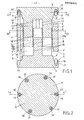
- FIG. 1 shows an axial section through an annular casing 1 and through a lower and an upper end plate, including the respective core arrangements and the wax model of the device according to the invention in a partially opened state.
- the annular jacket 1 has a lower separating surface 2 and an upper separating surface 3.
- the ends of the annular jacket 1 are conical, the lower conical surface being denoted by 1 'and the upper conical surface being denoted by 1 ".
- both the lower end plate 4 have a separating surface 5 and a conical surface 4', as well as that upper end plate 6 on a separating surface 7 and a conical surface 6.
- the separating surfaces 2 and 3 of the annular casing 1 and the separating surfaces 5 and 7 of the lower 4 and the upper end plate 6 are designed plane-parallel and are in the case when the three parts 1 , 4 and 6 of the device are directly closed to one another.
- the conical surface 1 'of the annular casing 1 and the conical surface 4' of the lower end plate 4 and the conical surface 1 "of the annular casing 1 and the conical surface 6 ' of the upper end plate 6 are each plane-parallel and also lie directly on top of one another when the three parts 1, 4 and 6 of the device are closed on.
- the conical surface 1 ', 1 ", 4' and 6 ' ensures coaxial centering of the annular jacket 1 with the lower 4 and upper end plate 6 when the device is closed.
- the lower end plate 4 with a first core arrangement 8 and the upper end plate 6 with a second core arrangement 9 are each formed in one piece, so that the two core arrangements 8, 9 are also mutually centered when the device is closed.
- Both the annular casing 1 and the lower 4 and upper end plate 6 with the respective core arrangements 8, 9 consist of a heat-resistant steel alloy.
- the walls 10, 11 of the core arrangements 8, 9 appear partly as surfaces and partly as straight lines.
- the tapering of the core walls 10, 11 from their base on the lower 4 or on the upper end plate 6 to the end thereof is not shown since the suit is very small and is only 40 'at most.
- the wax model 18 can also be seen in section in FIG. 1.
- the cylindrical surfaces of the wax model 18a and 18b are connected over their entire axial length by webs 1,8 ', which can only be seen in part in FIG. 1, since they are partially covered by the core arrangements 8, 9.
- the device is partially open in FIG. 1, the walls 10, 11 of the core arrangements 8, 9 still seem to rest against the wax model 18a, b.
- the distances between the walls 10, 11 of the core arrangements 8, 9 and the wax model 18a, b are so small that they cannot be represented in the drawing.
- a plurality of bores 12 for upper guide pins 14 and a plurality of bores 13 for lower guide pins 15 are formed in the annular casing 1.
- Fig. 1 only a bore 12 and an upper guide pin 14 and part of a lower guide pin 15 can be seen.
- the spring-loaded forcing bolts 17 are arranged in the separating surfaces 5 and 7 of the lower 4 or upper end plate 6. They are held in stepped bores 16, of which only one forcing pin 17 and one bore 16 are visible in FIG. 1 is.
- the push pin 17 and the associated functional parts are illustrated in FIG. 5 in detail.
- the stepped bores 16 including the push-off bolts 17 are evenly distributed over the circumference and between the bores 16 there are upper guide pins 14 which are connected to the upper end plate 6 by threads 14 ′.
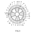
- FIG. 3 shows the section III-III from FIG. 1, which shows the arrangement and the geometric shape of the wax model 18 in the radial direction.
- the wax model 18 consists of two coaxial cylinders 18a, b, which are mutually connected by webs 18 '.
- Fig. 3 the parts of the upper core assembly 9, the wax model 18 and the annular shell 1 are cut, while the parts of the lower core assembly 8 are shown in plan view.
- the example embodiment of the core arrangements 8 and 9 shows that the middle part is part of the lower core arrangement 8.
- the sectional area of the annular shell 1 is also the distribution, once the offset bores at 120 0 12 13 including seen, including the upper guide pin 14, and each offset by 120 ° holes of the lower guide pins 15 °.
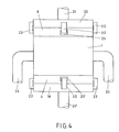
- FIG. 4 shows an exemplary embodiment of the subject matter of the invention, the pressing elements 19, 20, 21, 21 'and holding elements 22, 23, 23', 24 also being shown in simplified form.
- the device is supported by a lower press plate 19 on the lower press die 21 'and is over the upper Press plate 20 pressed together by the punch 21.
- the lower 19 and upper press plate 20 are held and guided both by the lower press ram 21 'and by the upper press ram 21.
- fastening pieces 22 are provided which connect the lower press plate 19 and the lower end plate 4 and the press plate 20 to the upper end plate 6.
- the fastening pieces 22 are hook-shaped and engage in recesses 23, 23 'of the upper 6 and the lower end plate 4.
- the arrangement of the middle front fastening pieces 22 in the recesses 23, 23 ' can be seen particularly well in FIG. 4.
- the annular jacket 1 is held or guided by holders 24 with play, of which only two are shown for better clarity.
- FIG. 5 shows an enlarged partial section of an exemplary embodiment through the spring-loaded forcing pin 17 and a helical spring.
- the push pin 17 is arranged in the stepped bore 16, the smaller diameter of the stepped bore 16 corresponding to that of the push pin 17, and the larger diameter of the stepped bore 16 being determined by the outer diameter of the helical spring 25.
- the coil spring 25 is drawn in the compressed position. It is supported with the lower end on the annular extension 26 of the push-off bolt 17 and presses it against the separating surface 2 or 3 of the annular casing 1. If the contact pressure of the press punches 21, 21 'on the lower 19 and upper press plate 20 is released, it moves the push-off bolt 17 out of the bore 16 until its annular boundary 26 abuts the limiting disk 27 and is thus prevented from jumping out.
- the limiting disk 27 is embedded in the separating surface 7 of the upper end plate 6 in the present exemplary embodiment and fastened with screws 28.
- FIG. 6 Another variant of springs is shown in Fig. 6.
- a leaf spring 30 In a recess 29, a leaf spring 30 is inserted, which in the present example directly contacts the separating surface 3 of the annular casing 1 and has the same function as the spring described in FIG. 5.
- the leaf spring 30 is held at its ends 31 in extensions of the recess 29 without tools.
- the device is ready for operation when all functional parts are assembled as shown in FIG. 4.
- the end plates 4, 6 are pressed hydraulically between the press plates 19, 20 onto the annular jacket 1, so that the conical surfaces 1 ', 1 ", 4', 6 ', the parts 1, 4, 6 and the lower 8 and upper core arrangement Center each other 9.
- the push-off bolts 17 are inserted and tensioned in bores 16 by the assembly of the device or the leaf springs 30 in recesses 29.
- the push-off bolts are tensioned by helical springs 25.
- the leaf springs are tensioned in accordance with 6 directly through the separating surfaces 2 and 3 of the ring-shaped jacket 1. Then liquid wax is introduced between the walls 10, 11 of the lower 8 and upper core arrangement 9.
- the external pressure of the press punches 21, 21 ' reduced to zero by pressing the valve on the pressure plates 19, 20 and on the lower 4 and upper end plate 6.
- the pressure immediately breaks down s, whereby the spring-loaded forcing bolts 17 or the leaf springs 30 act suddenly on the separating surfaces 2 and 3 of the annular casing 1, so that the lower 4 and Upper end plate 6, together with the core arrangements 8, 9, are separated from the annular jacket 1 and thus also from the wax model 18 by a distance of approximately 3 mm.
- This path corresponds to the distance from the lower part of the annular extension 26 of the push-off pin 17 to the annular limiting disk 27 or is dependent on the characteristic of the leaf spring 30.
- the springs 25, 30, which suddenly release in opposite directions, generate the breakaway torque required to to separate the wax model 18 adhering to the walls 10, 11 of the core arrangements 8, 9 as a result of this.
- the core arrangements 8, 9 have a tightening of at most 40 '.
- the wax model 18 is held in place by the ring-shaped casing 1 after it has been released.
Landscapes
- Engineering & Computer Science (AREA)
- Mechanical Engineering (AREA)
- Manufacturing & Machinery (AREA)
- Molds, Cores, And Manufacturing Methods Thereof (AREA)
- Production Of Liquid Hydrocarbon Mixture For Refining Petroleum (AREA)
- Moulds For Moulding Plastics Or The Like (AREA)
Abstract
Description
- Die Erfindung bezieht sich auf eine mehrteilige Vorrichtung zur Herstellung von dünnwandigen Wachsmodellen, enthaltend eine untere Abschlussplatte mit einer Anordnung von ersten Kernen, und einer oberen Abschlussplatte mit einer Anordnung von zweiten Kernen, und einem seitlich angeordneten Mantel zum Umfassen des herzustellenden Wachsmodelles.
- Die für die Fertigung von Feinguss benötigten Wachsmodelle werden in mehrteiligen Vorrichtungen, den sogenannten Matrizen oder Werkzeugen hergestellt. Diese bestehen in der Regel aus warmfesten Stahllegierungen.
- Nach dem Erstarren des Wachsmodelles in dem Werkzeug muss es aus diesem entfernt werden. Dieser Vorgang bildet die kritischste Phase im gesamten Herstellungsprozess, weil das Oberflächen-Volumen-Verhältnis des Wachsmodelles extrem gross ist und demzufolge das Wachsmodell stark an den Kernwänden des Werkzeuges haftet.Da die Formgebung des Wachsmodells über die Flüssig-Fest-Phase oder unter Umgehung der Flüssig-Phase im teigigen Zustand bei Temperaturen unterhalb der Liquidustemperatur erfolgt, ist mit höheren Kontraktionswerten des Wachses und mit entsprechend grösserer Adhäsion des Wachses an den Kernwänden zu rechnen.
- Hinzu kommt weiterhin, dass der Werkstoff Wachs spröde ist und eine geringe Eigenfestigkeit aufweist. Beim Oeffnen des Werkzeuges entstehen Zugspannungen im erstarrten Wachs und es besteht daher Gefahr von Rissbildung, selbst wenn die Wände der Kernanordnungen des Werkzeuges mit Anzug versehen sind.
- Eine Einrichtung zum Entfernen von geformten Gegenständen aus einem formenden Gehäuse ist aus CH-PS 548 240 bekannt. Hierbei wird mittels einer membranartigen druckluftbetätigten gummielastischen Scheibe, ein aus gepresstem Sand bestehender Kern für die Herstellung von hohlen Gussstücken aus einem formenden Gehäuse entfernt.
- Diese Einrichtung ist geeignet für Sandguss, bei dem das Oberflächen-Volumen-Verhältnis der geformten Gegenstände vergleichsweise geringer ist als bei gegossenen Wachsmodellen, und ausserdem sind die Anforderungen, die an die Operation des Abtrennens des geformten Gegenstandes vom formenden Gehäuse gestellt werden, bei Sandguss bei weitem nicht so gross wie bei der Formgebung von dünnwandigen Wachsmodellen in einem Werkzeug.
- Die zerstörungsfreie Abtrennung erstarrter dünnwandiger Wachsmodelle von den Wänden der Kernanordnungen ist demnach wesentlich problematischer als bei Sandguss und ist mit den in der Giessereiindustrie derzeit bekannten Einrichtungen nur unzulänglich durchführbar.
- Hier will die Erfindung Abhilfe schaffen.
- Die Erfindung, wie sie in den Ansprüchen gekennzeichnet ist, löst die Aufgabe, eine Vorrichtung und ein Verfahren zu schaffen, wodurch Wachsmodelle für Feinguss unter allgemeinen Produktionsbedingungen reproduzierbar, in qualitativ einwandfreiem Zustand und wirtschaftlich hergestellt werden können, indem zur Erzeugung des Losbrechmomentes zwischen dem Wachsmodell und den Kernwänden, sowohl in den Trennflächen zwischen dem Mantel und der unteren Abschlussplatte als auch in den Trennflächen zwischen dem Mantel und der oberen Abschlussplatte, und zwar in den Trennflächen des Mantels und/ oder der Abschlussplatten, jeweils mindestens drei Federn angeordnet sind, die durch die jeweiligen gegenüberliegenden Trennflächen in die eigenen Trennflächen einpressbar sind, so dass sie auf die gegenüberliegenden Trennflächen einen Druck ausüben können, wodurch gleichzeitig und sprungartig, sowohl in den Trennflächen zwischen dem Mantel und der unteren Abschlussplatte als auch in den Trennflächen zwischen dem Mantel und der oberen Abschlussplatte eine abstossende Kraft erreicht werden kann.
- Diese Vorrichtung weist folgenden Vorteil auf:
- - Es wird ein gleichzeitiges spielfrei arbeitendes und axial gegenseitiges Abziehen der ersten und der zweiten Kernanordnung vom Wachsmodell erreicht.
- Aufgrund des gleichzeitigen sprungartigen und axial gegenseitigen Abziehens des Wachsmodells von der ersten und der zweiten Kernanordnung wird ein hohes und auf alle Oberflächenteile des Wachsmodells gleichmässig wirkendes Losbrechmoment erzielt, wodurch Zerstörungen am Wachsmodell vermieden werden, was mit den derzeit bekannten pneumatischen oder hydraulischen Abzieheinrichtungen, die mit Spiel behaftet sind, nicht möglich ist.
- Entsprechend Anspruch 2 sind die Federn. in je einer Bohrung in den Trennflächen von Mantel und/oder unteren und oberen Abschlussplatte eingelassen und wirken auf je einen Abdrückbolzen.
- Nach Anspruch 3 ist bei Entlastung der Federn der Weg der Federn insbesondere durch eine ringförmige Scheibe begrenzt, wodurch der Weg für jeden Bolzen gleich ist.
- Die vorteilhafte Wirkung gemäss den Weiterbildungen nach den Ansprüchen 2 und 3 besteht darin, dass die sprungartig sich entlastende Federkraft symmetrisch und spielfrei direkt auf die Trennflächen von Mantel und/oder unterer und oberer Abschlussplatte wirkt, wodurch eine axiale Zentrierung beim Abziehen der Kernanordnungen nach entgegengesetzten Richtungen ermöglicht wird.
- Gemäss Anspruch 4 sind die Federn Blattfedern, die in Ausnehmungen in den beiden Trennflächen von Mantel und/oder unteren und oberen Abschlussplatte eingelassen sind und die mit einem Teil der Blattfedern innerhalb der Ausnehmungen befestigt sind.
- Durch die Anordnung der Blattfedern wird eine direkte Kraftübertragung auf die beiden Trennflächen des Mantels und/oder der unteren und oberen Abschlussplatte unter Umgehung des Abdrückbolzens erreicht.
- Nach Anspruch 5 weisen die Wände der Kerne einen Anzug von höchstens 40' auf. Mit dieser Grosse des Anzugs ist einmal die Massgenauigkeit des Feingusses gewährleistet, zum anderen wird das Abziehen der Kernanordnungen vom Wachsmodell begünstigt.
- Entsprechend Anspruch 6 weisen die Federn eine Spannungs-Dehnungscharakteristik auf, die sich nicht mehr als - 5% unterscheidet.
- Hierdurch wird die vorteilhafte Wirkung der Ausgestaltung gemäss Anspruch 2 und 3 noch verstärkt.
- Beim erfindungsgemässen Verfahren zur Herstellung von Wachsmodellen gemäss Anspruch 7 werden die untere, die obere Abschlussplatte und der Mantel zusammengepresst, die Federn gespannt, in die freien Räume zwischen den Kernanordnungen nach vorheriger Evakuierung flüssiges Wachs eingebracht, und nach dem Erstarren des Wachses wird der äussere Druck auf die untere Abschlussplatte und die obere Abschlussplatte gleichzeitig gelöst, wodurch sprungartig die Federn sowohl in den Trennflächen zwischen dem Mantel und der unteren Abschlussplatte als auch in den Trennflächen zwischen dem Mantel und der oberen Abschlussplatte, die untere Abschlussplatte mit der ersten Kernanordnung und die obere Abschlussplatte mit der zweiten Kernanordnung von dem Mantel trennen und damit auch automatisch das Wachsmodell, durch gleichzeitige und sprungartige Ueberwindung der Adhäsion des Wachsmodells zu den Wänden der Kernanordnungen, von den Kernanordnungen trennen, und die beiden Kernanordnungen und der Mantel relativ zueinander in axialer Richtung gegenseitig voneinander wegtransportiert werden, so dass das Wachsmodell frei wird.
- Die Erfindung wird nachstehend anhand von in der Zeichnung dargestellten Ausführungsbeispielen erläutert.
- In der Zeichnung zeigt:
- Fig. 1 einen axialen Schnitt durch einen ringförmigen Mantel sowie durch eine untere und eine obere Abschlussplatte einschliesslich der jeweiligen Kernanordnungen und das Wachsmodell, wobei die erfindungsgemässe Vorrichtung sich in teilweise geöffnetem Zustand befindet
- Fig. 2 einen Schnitt II-II gemäss Fig. 1 senkrecht zur Achse durch die obere Abschlussplatte
- Fig. 3 einen Schnitt III-III gemäss Fig. 1 senkrecht zur Achse durch den ringförmigen Mantel sowie durch die zweite Kernanordnung und das Wachsmodell
- Fig. 4 eine Vorderansicht der erfindungsgemässen Vorrichtung im geschlossenen Zustand, wobei die für die Funktionsweise erforderlichen Hilfsmittel vereinfacht schematisch dargestellt sind
- Fig. 5 einen vergrösserten teilweisen Schnitt einer beispielsweisen Ausführungsform durch einen Abdrückbolzen und eine Schraubenfeder
- Fig. 6 einen vergrösserten Schnitt einer weiteren beispielsweisen Ausführungsform durch eine Blattfeder.
- In Fig. 1 ist ein axialer Schnitt durch einen ringförmigen Mantel 1 sowie durch eine untere und eine obere Abschlussplatte, einschliesslich der jeweiligen Kernanordnungen und das Wachsmodell der erfindungsgemässen Vorrichtung in teilweise geöffnetem Zustand dargestellt.
- Der ringförmige Mantel 1 weist eine untere Trennfläche 2 und eine obere Trennfläche 3 auf. Die Enden des ringförmigen Mantels 1 sind konisch ausgebildet, wobei die untere konische Fläche mit 1' und die obere konische Fläche mit l" bezeichnet sind. Entsprechend dazu weisen sowohl die untere Abschlussplatte 4 eine Trennfläche 5 und eine konische Fläche 4', als auch die obere Abschlussplatte 6 eine Trennfläche 7 und eine konische Fläche 6' auf. Die Trennflächen 2 und 3 des ringförmigen Mantels 1 und die Trennflächen 5 und 7 der unteren 4 und der oberen Abschlussplatte 6 sind planparallel ausgestaltet und liegen im Fall, wenn die drei Teile 1, 4 und 6 der Vorrichtung geschlossen sind, unmittelbar aufeinander auf. Ebenso sind die konische Fläche 1' des ringförmigen Mantels 1 und die konische Fläche 4' der unteren Abschlussplatte 4 und die konische Fläche 1" des ringförmigen Mantels 1 und die konische Fläche 6' der oberen Abschlussplatte 6 jeweils planparallel ausgebildet und liegen ebenfalls, wenn die drei Teile 1, 4 und 6 der Vorrichtung geschlossen sind, unmittelbar aufeinander auf. Die konische Fläche 1', 1", 4' und 6' gewährleistet eine koaxiale Zentrierung des ringförmigen Mantels 1 mit der unteren 4 und oberen Abschlussplatte 6 bei geschlossener Vorrichtung.
- In der beispielsweisen Ausführungsform gemäss Fig. 1 sind die untere Abschlussplatte 4 mit einer ersten Kernanordnung 8 und die obere Abschlussplatte 6 mit einer zweiten Kernanordnung 9 jeweils einstückig ausgebildet, so dass die beiden Kernanordnungen 8, 9 im geschlossenen Zustand der Vorrichtung ebenfalls gegenseitig zentriert sind. Sowohl der ringförmige Mantel 1 als auch die untere 4 und obere Abschlussplatte 6 mit den jeweiligen Kernanordnungen 8, 9 bestehen aus einer warmfesten Stahllegierung.
- In der Schnittdarstellung der Fig. 1 erscheinen die Wände 10, 11 der Kernanordnungen 8, 9 zum Teil als Flächen und zum Teil als Geraden. Die Verjüngung der Kernwände 10, 11 von deren Basis an der unteren 4 bzw. an der oberen Abschlussplatte 6 bis hin zu deren Ende, ist, da der Anzug sehr gering ist und lediglich höchstens 40' beträgt, nicht dargestellt. In Fig. 1 sind weiterhin im Schnitt das Wachsmodell 18 zu sehen. Die zylindrischen Flächen des Wachsmodelles 18a und 18b sind über deren gesamte axiale Länge durch Stege 1,8' verbunden, die in Fig. 1 nur zum Teil zu sehen sind, da sie durch die Kernanordnungen 8, 9 teilweise verdeckt sind. Obwohl in Fig. 1 die Vorrichtung teilweise geöffnet ist, liegen die Wände 10, 11 der Kernanordnungen 8, 9 scheinbar immer noch an dem Wachsmodell 18a, b an. In Wirklichkeit liegt nur der äussere Umfang des Wachsmodells 18a, am ringförmigen Mantel 1 auf. Die Abstände zwischen den Wänden 10, 11 der Kernanordnungen 8, 9 und dem Wachsmodell 18a, b sind jedoch derart klein, dass man sie zeichnerisch nicht darstellen kann.
- Im ringförmigen Mantel 1 sind mehrere Bohrungen 12 für obere Führungsstifte 14 und mehrere Bohrungen 13 für untere Führungsstifte 15 ausgebildet. In Fig. 1 ist nur eine Bohrung 12 und ein oberer Führungsstift 14 sowie ein Teil eines unteren Führungsstiftes 15 zu sehen. In den Trennflächen 5 und 7 der unteren 4 bzw. oberen Abschlussplatte 6 sind die federbelasteten Abdrückbolzen 17 angeordnet. Sie werden in abgestuften Bohrungen 16 gehalten, von denen in Fig. 1 nur jeweils ein Abdrückbolzen 17 und eine Bohrung 16 sichtbar ist. Der Abdrückbolzen 17 und die dazugehörigen Funktionsteile sind in Fig. 5 im einzelnen veranschaulicht.
- In Fig. 2 sowie in den weiteren Figuren sind gleiche Funktionsteile mit den selben Bezugsziffern wie in Fig. 1 bezeichnet.
- In Fig. 2 ist der Schnitt II-II aus Fig. 1 gezeigt. Es sind in einer beispielsweisen Ausführungsform die abgestuften Bohrungen 16 einschliesslich der Abdrückbolzen 17 gleichmässig über den Umfang verteilt und zwischen den Bohrungen 16 sind obere Führungsstifte 14 vorgesehen, die durch Gewinde 14' mit der oberen Abschlussplatte 6 verbunden sind.
- In Fig. 3 ist der Schnitt III-III aus Fig. 1 dargestellt, der die Anordnung und die geometrische Form des Wachsmodelles 18 in radialer Richtung zeigt. Das Wachsmodell 18 besteht in dieser beispielsweisen Ausführungsform aus zwei koaxialen Zylindern 18a, b, die gegenseitig durch Stege 18' verbunden sind. In Fig. 3 sind die Teile der oberen Kernanordnung 9, das Wachsmodell 18 sowie der ringförmige Mantel 1 geschnitten, während die Teile der unteren Kernanordnung 8 in Draufsicht gezeigt sind.
- Die beispielsweise Ausführungsform der Kernanordnungen 8 bzw. 9 zeigt, dass der mittlere Teil Bestandteil der unteren Kernanordnung 8 ist. In der Schnittfläche des ringförmigen Mantels 1 ist gleichfalls die Verteilung, einmal die jeweils um 1200 versetzten Bohrungen 12 einschliesslich des oberen Führungsstiftes 14 sowie die jeweils um 120° versetzten Bohrungen 13 einschliesslich der unteren Führungsstifte 15 zu sehen.
- Fig. 4 zeigt eine beispielsweise Ausführungsform des Erfindungsgegenstandes, wobei auch die Press- 19, 20, 21, 21' und Halteelemente 22, 23, 23', 24 vereinfacht dargestellt sind. Die Vorrichtung ist mit einer unteren Pressplatte 19 auf dem unteren Pressstempel 21' abgestützt und wird über die obere Pressplatte 20 durch den Pressstempel 21 zusammengepresst. Die untere 19 und obere Pressplatte 20 werden sowohl von dem unteren Pressstempel 21' als auch von dem oberen Pressstempel 21 gehalten und geführt. Ausserdem sind Befestigungsstücke 22 vorgesehen, die die untere Pressplatte 19 und die untere Abschlussplatte 4 sowie die Pressplatte 20 mit der oberen Abschlussplatte 6 verbinden. Die Befestigungsstücke 22 sind hakenförmig ausgebildet und greifen in Ausnehmungen 23, 23' der oberen 6 und der unteren Abschlussplatte 4 ein. In Fig. 4 ist die Anordnung der mittleren vorderen Befestigungsstücke 22 in den Ausnehmungen 23, 23' besonders gut zu erkennen. Der ringförmige Mantel 1 wird von Halterungen 24 mit Spiel gehalten bzw. geführt, von denen wegen besserer Uebersicht nur zwei dargestellt sind.
- In Fig. 5 ist ein vergrösserter teilweiser Schnitt einer beispielsweisen Ausführungsform durch den federdrehbelasteten Abdrückbolzen 17 und einer Schraubenfeder dargestellt. Der Abdrückbolzen 17 ist in der abgestuften Bohrung 16 angeordnet, wobei der kleinere Durchmesser der abgestuften Bohrung 16 demjenigen des Abdrückbolzens 17 entspricht, und der grössere Durchmesser der abgestuften Bohrung 16 durch den Aussendurchmesser der Schraubenfeder 25 festgelegt ist.
- In Fig. 5 ist die Schraubenfeder 25 in zusammengepresster Lage gezeichnet. Sie stützt sich mit dem unteren Ende auf die ringförmige Erweiterung 26 des Abdrückbolzens 17 und drückt diesen gegen die Trennfläche 2 oder 3 des ringförmigen Mantels 1. Wird der Anpressdruck der Pressstempel 21, 21' an die untere 19 und obere Pressplatte 20 gelöst, bewegt sich der Abdrückbolzen 17 so lange aus der Bohrung 16 heraus, bis dessen ringförmige Begrenzung 26 an die Begrenzungsscheibe 27 anstösst, und er somit am Herausspringen gehindert wird. Die Begrenzungsscheibe 27 ist im vorliegenden Ausführungsbeispiel in die Trennfläche 7 der oberen Abschlussplatte 6 eingelassen und mit Schrauben 28 befestigt.
- Eine weitere Variante von Federn ist in Fig. 6 dargestellt. In einer Ausnehmung 29 ist eine Blattfeder 30 eingelegt, die im vorliegenden Beispiel direkt die Trennfläche 3 des ringförmigen Mantels 1 berührt und dieselbe Funktion hat wie die in Fig. 5 beschriebene Feder. Die Blattfeder 30 wird an ihren Enden 31 in Erweiterungen der Ausnehmung 29 ohne Hilfsmittel gehalten.
- Die Funktionsweise der erfindungsgemässen Vorrichtung wird nachstehend näher erläutert.
- An sich bekannte, nicht zum unmittelbaren Verständnis der Funktionsweise erforderlichen Bestandteile, beispielsweise Wachseinspritzkanäle, sind in der Zeichnung weggelassen worden.
- Die Vorrichtung ist betriebsbereit, wenn alle Funktionsteile so zusammengesetzt sind, wie es Fig. 4 zeigt. Die Abschlussplatten 4, 6 werden zwischen den Pressplatten 19, 20 auf den ringförmigen Mantel 1 hydraulisch gepresst, so dass die konischen Flächen 1', 1", 4', 6' die Teile 1, 4, 6 sowie die untere 8 und obere Kernanordnung 9 gegenseitig zentrieren. Die Abdrückbolzen 17 sind durch den Zusammenbau der Vorrichtung in Bohrungen 16 oder die Blattfedern 30 in Ausnehmungen 29 eingeschoben und gespannt. Wie aus Fig. 5 ersichtlich ist, erfolgt das Spannen der Abdrückbolzen durch Schraubenfedern 25. Das Spannen der Blattfedern erfolgt gemäss Fig. 6 direkt durch die Trennflächen 2 und 3 des ringförmigen Mantels 1. Danach wird, zwischen den Wänden 10, 11 der unteren 8 und oberen Kernanordnung 9 flüssiges Wachs eingebracht. Nach dem Erstarren des Wachses wird der äussere Druck der Pressstempel 21, 21' auf die Pressplatten 19, 20 und auf die untere 4 und obere Abschlussplatte 6 durch Ventilbetätigung auf Null abgebaut. Infolge der Inkompressibilität des Drucköles bricht der Druck unmittelbar zusammen, wodurch sprungartig die federbelasteten Abdrückbolzen 17 oder die Blattfedern 30 auf die Trennflächen 2 und 3 des ringförmigen Mantels 1 einwirken, so dass die untere- 4 und ober Abschlussplatte 6, samt den Kernanordnungen 8, 9 vom ringförmigen Mantel 1 und damit auch vom Wachsmodell 18, um einen Weg von ca. 3 mm getrennt werden. Dieser Weg entspricht dem Abstand vom unteren Teil der ringförmigen Erweiterung 26 des Abdrückbolzens 17 bis zur ringförmigen Begrenzungsscheibe 27 oder ist abhängig von der Charakteristik der Blattfeder 30. Die in entgegengesetzten Richtungen sprungartig sich entlastenden Federn 25, 30 erzeugen das Losbrechmoment, das erforderlich ist, um das infolge Adhäsion an den Wänden 10, 11 der Kernanordnungen 8, 9 anhaftende Wachsmodell 18, von diesen zu trennen. Zur Verringerung des Losbrechmomentes und um das Wachsmodell 18 vor Beschädigung zu schützen, weisen die Kernanordnungen 8, 9 einen Anzug von höchstens 40' auf. Das Wachsmodell 18 wird nach dem Lösen durch den ringförmigen Mantel 1 festgehalten.
- Um die richtige Funktionsweise der Vorrichtung zu ermöglichen, wird der ringförmige Mantel 1 von den Halterungen 24 mit Spiel gehalten. Aus Gründen besserer Uebersicht sind in Fig. 4 nur zwei Halterungen 24 gezeichnet.
- Die Oeffnungsfolge der Vorrichtung nach dem Erstarren des eingebrachten Wachses geschieht in nachstehend aufgeführten Schritten:
- 1. Erzeugung eines Losbrechmomentes gleichzeitig und sprungartig in axial entgegengesetzte Richtungen durch federbelastete Abdrückbolzen 17 bzw. direkt durch Blattfedern 30 in den oberen 3, 7 und unteren Trennflächen 2, 5 der Vorrichtung und dadurch Trennung der unteren 4 und oberen Abschlussplatte 6 von dem Mantel 1 und der Wände 10, 11 der Kernanordnungen 8, 9 vom Wachsmodell 18, 18' um ca. 3 mm.
- 2. Ausziehen der oberen Kernanordnung 9, wobei das Wachsmodell 18, 18' durch den ringförmigen Mantel 1 gehalten wird.
- 3. Abziehen des ringförmigen Mantels 1 einschliesslich des Wachsmodelles 18, 18' von der feststehenden unteren Kernanordnung 8.
- 4. Die Schritte 2 und 3 können durch mechanische und hydraulische Zusatzeinrichtungen kombiniert werden. Das Abziehen des ringförmigen Mantels 1 erfolgt dabei z.B..mit der halben Geschwindigkeit, mit welcher die obere Kernanordnung 9 nach oben weggezogen wird.
Claims (7)
Priority Applications (1)
| Application Number | Priority Date | Filing Date | Title |
|---|---|---|---|
| AT82201132T ATE9295T1 (de) | 1981-10-01 | 1982-09-13 | Vorrichtung und verfahren zur herstellung von duennwandigen wachsmodellen fuer feinguss. |
Applications Claiming Priority (2)
| Application Number | Priority Date | Filing Date | Title |
|---|---|---|---|
| CH632681 | 1981-10-01 | ||
| CH6326/81 | 1981-10-01 |
Publications (2)
| Publication Number | Publication Date |
|---|---|
| EP0076531A1 true EP0076531A1 (de) | 1983-04-13 |
| EP0076531B1 EP0076531B1 (de) | 1984-09-12 |
Family
ID=4307787
Family Applications (1)
| Application Number | Title | Priority Date | Filing Date |
|---|---|---|---|
| EP82201132A Expired EP0076531B1 (de) | 1981-10-01 | 1982-09-13 | Vorrichtung und Verfahren zur Herstellung von dünnwandigen Wachsmodellen für Feinguss |
Country Status (6)
| Country | Link |
|---|---|
| US (1) | US4539168A (de) |
| EP (1) | EP0076531B1 (de) |
| JP (1) | JPS5868450A (de) |
| AT (1) | ATE9295T1 (de) |
| DE (1) | DE3260732D1 (de) |
| DK (1) | DK432782A (de) |
Cited By (1)
| Publication number | Priority date | Publication date | Assignee | Title |
|---|---|---|---|---|
| EP0364356A3 (de) * | 1988-10-11 | 1991-11-13 | Motor Wheel Corporation | Druckgiessform für Räder aus faserverstärktem Verbundwerkstoff |
Families Citing this family (2)
| Publication number | Priority date | Publication date | Assignee | Title |
|---|---|---|---|---|
| IT1179524B (it) * | 1984-12-21 | 1987-09-16 | Pirelli | Pressa di vulcanizzazione a doppio stampo |
| ATE247548T1 (de) * | 1999-08-20 | 2003-09-15 | Erwin Wimmer | Formwerkzeug für spritz- oder druckgussmaschinen |
Citations (6)
| Publication number | Priority date | Publication date | Assignee | Title |
|---|---|---|---|---|
| GB705314A (en) * | 1951-09-07 | 1954-03-10 | Alfa Plastics Ltd | Improvements in and relating to the manufacture of cotton and like reels |
| CH343121A (de) * | 1956-05-30 | 1959-12-15 | Herrmann Ernst | Verfahren zur Herstellung von Flaschenverschlüssen aus Kunststoff, Anlage zur Durchführung des Verfahrens und nach dem Verfahren hergestellter Verschluss |
| FR1526950A (fr) * | 1966-12-12 | 1968-05-31 | Procédé pour la fabrication de pièces lisses en matière plastique, moule d'injection pour la mise en oeuvre dudit procédé, et pièces ainsi obtenues | |
| US3591898A (en) * | 1969-09-22 | 1971-07-13 | Herter Inc S | Molding of all-plastic shot shell cases |
| DE2202061A1 (de) * | 1972-01-17 | 1973-07-26 | Hasel Heinz Dr Rer Nat Dipl Ph | Formwerkzeug zum herstellen von hohlkastenfoermigen, an ihrer oberseite mit kupplungszapfen versehenen spielbausteinen aus thermoplastischem kunststoff |
| FR2189199A1 (de) * | 1972-06-16 | 1974-01-25 | Precision Metalsmiths Inc |
Family Cites Families (12)
| Publication number | Priority date | Publication date | Assignee | Title |
|---|---|---|---|---|
| US658680A (en) * | 1900-03-15 | 1900-09-25 | John C Scheufler | Machine for making crayons. |
| GB191107875A (en) * | 1911-03-29 | 1911-07-27 | Frans Justinus Nilsson | Method of and Apparatus for Manufacturing Radiators, Sectional Boilers, and the like. |
| US1427149A (en) * | 1919-11-17 | 1922-08-29 | Walter G Cook | Artificial comb and the art of producing the same |
| US2057540A (en) * | 1928-11-15 | 1936-10-13 | Plastic Res And Engineering Co | Machine for molding candles |
| US2135803A (en) * | 1935-12-16 | 1938-11-08 | Johnson Lab Inc | Method of and means for molding plastic materials which do not flow easily |
| US3004291A (en) * | 1958-01-14 | 1961-10-17 | Eric Dent | Apparatus for forming brushes |
| DE1173732B (de) * | 1960-06-08 | 1964-07-09 | Gen Motors Corp | Gegossene Turbinenschaufel |
| US3145423A (en) * | 1961-09-25 | 1964-08-25 | Prec Associates Inc | Air-releasing mold |
| US3271491A (en) * | 1962-01-23 | 1966-09-06 | Mikkelborg Gunnar | Method of preparing within a mold of rubber or of a material having similar properties shapes of wax or similar materials for use in the so-called lostwax-molding method |
| US3673302A (en) * | 1967-01-09 | 1972-06-27 | Globe Union Inc | Method for fabricating battery cases |
| US3930780A (en) * | 1973-07-20 | 1976-01-06 | Beatrice Foods Co. | Injection molding apparatus for partitioned containers |
| DE2634152C3 (de) * | 1976-07-29 | 1979-04-19 | Johannes 8641 Neuses Wuendsch | Gießform für Gußstücke mit einem auszuformenden Gewinde |
-
1982
- 1982-09-13 AT AT82201132T patent/ATE9295T1/de active
- 1982-09-13 EP EP82201132A patent/EP0076531B1/de not_active Expired
- 1982-09-13 DE DE8282201132T patent/DE3260732D1/de not_active Expired
- 1982-09-22 US US06/421,100 patent/US4539168A/en not_active Expired - Lifetime
- 1982-09-29 JP JP57168724A patent/JPS5868450A/ja active Granted
- 1982-09-29 DK DK432782A patent/DK432782A/da not_active Application Discontinuation
Patent Citations (6)
| Publication number | Priority date | Publication date | Assignee | Title |
|---|---|---|---|---|
| GB705314A (en) * | 1951-09-07 | 1954-03-10 | Alfa Plastics Ltd | Improvements in and relating to the manufacture of cotton and like reels |
| CH343121A (de) * | 1956-05-30 | 1959-12-15 | Herrmann Ernst | Verfahren zur Herstellung von Flaschenverschlüssen aus Kunststoff, Anlage zur Durchführung des Verfahrens und nach dem Verfahren hergestellter Verschluss |
| FR1526950A (fr) * | 1966-12-12 | 1968-05-31 | Procédé pour la fabrication de pièces lisses en matière plastique, moule d'injection pour la mise en oeuvre dudit procédé, et pièces ainsi obtenues | |
| US3591898A (en) * | 1969-09-22 | 1971-07-13 | Herter Inc S | Molding of all-plastic shot shell cases |
| DE2202061A1 (de) * | 1972-01-17 | 1973-07-26 | Hasel Heinz Dr Rer Nat Dipl Ph | Formwerkzeug zum herstellen von hohlkastenfoermigen, an ihrer oberseite mit kupplungszapfen versehenen spielbausteinen aus thermoplastischem kunststoff |
| FR2189199A1 (de) * | 1972-06-16 | 1974-01-25 | Precision Metalsmiths Inc |
Non-Patent Citations (1)
| Title |
|---|
| JAPAN PLASTICS AGE, Band 11, Nr. 10, Oktober 1973, Seiten 41-48, Tokyo, JP. * |
Cited By (1)
| Publication number | Priority date | Publication date | Assignee | Title |
|---|---|---|---|---|
| EP0364356A3 (de) * | 1988-10-11 | 1991-11-13 | Motor Wheel Corporation | Druckgiessform für Räder aus faserverstärktem Verbundwerkstoff |
Also Published As
| Publication number | Publication date |
|---|---|
| JPS6342533B2 (de) | 1988-08-24 |
| EP0076531B1 (de) | 1984-09-12 |
| ATE9295T1 (de) | 1984-09-15 |
| DE3260732D1 (en) | 1984-10-18 |
| US4539168A (en) | 1985-09-03 |
| DK432782A (da) | 1983-04-02 |
| JPS5868450A (ja) | 1983-04-23 |
Similar Documents
| Publication | Publication Date | Title |
|---|---|---|
| DE69317809T2 (de) | Zusammenbau gepaarter einander angepasster Gussteile und ihr Herstellungsverfahren | |
| EP0030931B1 (de) | Verfahren zum Herstellen von Werkstücken, insbesondere von Brillenbügeln | |
| EP4076881B1 (de) | Vorrichtung zur herstellung von betonsteinen | |
| EP0999912A1 (de) | Vorrichtung zum bruchtrennen eines ringförmigen bauteils | |
| DE3102867A1 (de) | Vorrichtung zur verformen des endabschnittes eines rohres | |
| DE2829729C3 (de) | Maschine zum Abbrechen der Hälse der verlorenen Köpfe bei Gußstücken | |
| EP1385664B1 (de) | Verfahren und vorrichtung zum bearbeiten von ringartigen werkstücken | |
| EP0076531B1 (de) | Vorrichtung und Verfahren zur Herstellung von dünnwandigen Wachsmodellen für Feinguss | |
| EP1171260A1 (de) | Vorrichtung zum bruchtrennen eines werkstücks | |
| DE10151756C1 (de) | Vorrichtung zum Herstellen eines Tampons | |
| DE3850546T2 (de) | Verfahren zur Herstellung eines vorgearbeiteten Rohrteiles aus Kupferlegierung. | |
| WO2020169462A1 (de) | EINTEILIGER SPEISERKÖRPER ZUR VERWENDUNG BEIM GIEßEN VON METALLEN | |
| EP0061072A2 (de) | Spritzgiessform | |
| CH684171A5 (de) | Giessform-Fertigungsmaschine mit einem eine Formplatte entfernenden Vibrator. | |
| DE1045639B (de) | Spritzgussform zum Herstellen von Formkoerpern aus thermoplastischem Kunststoff, insbesondere Verschlusskappen fuer pharmazeutische Tablettenroehrchen | |
| DE68901647T2 (de) | Verfahren und werkzeugausruestung zur herstellung geschmiedeter niete. | |
| DE102019002187B4 (de) | Verfahren und Vorrichtung zum Herstellen eines Bauteils mit Gewinde | |
| EP0868954B1 (de) | Vorrichtung sowie Verfahren zur Herstellung eines Gusswerkstückes mit eingegossenem Einlegeteil | |
| DE8500656U1 (de) | Vorrichtung zur verwendung bei der herstellung einer giessform mit speiserhuelse | |
| DE3120655A1 (de) | Geschlitzter kolbenring und verfahren zu seiner herstellung | |
| DE3735735A1 (de) | Verfahren und vorrichtung zum druckgiessen von gussteilen | |
| DE102020107538B4 (de) | Formgebungsmaschine und/oder Baugruppe für eine Formgebungsmaschine und Verfahren zum Einstellen der Länge einer Zug- oder Druckstange einer Formgebungsmaschine und/oder einer Baugruppe | |
| DE1110997B (de) | Vorrichtung zum Herstellen von Laengsrippen an stabfoermigen Werkstuecken, wie Reibahlen, Gewindebohrern od. dgl. | |
| DE2550286B2 (de) | Druckgieß- und Spritzgießkokille | |
| DE2611505C3 (de) | Gießvorrichtung zur Herstellung von Harzisolatoren |
Legal Events
| Date | Code | Title | Description |
|---|---|---|---|
| PUAI | Public reference made under article 153(3) epc to a published international application that has entered the european phase |
Free format text: ORIGINAL CODE: 0009012 |
|
| AK | Designated contracting states |
Designated state(s): AT BE CH DE FR GB IT LI NL SE |
|
| 17P | Request for examination filed |
Effective date: 19830509 |
|
| ITF | It: translation for a ep patent filed | ||
| GRAA | (expected) grant |
Free format text: ORIGINAL CODE: 0009210 |
|
| AK | Designated contracting states |
Designated state(s): AT BE CH DE FR GB IT LI NL SE |
|
| PG25 | Lapsed in a contracting state [announced via postgrant information from national office to epo] |
Ref country code: NL Effective date: 19840912 Ref country code: BE Effective date: 19840912 |
|
| REF | Corresponds to: |
Ref document number: 9295 Country of ref document: AT Date of ref document: 19840915 Kind code of ref document: T |
|
| REF | Corresponds to: |
Ref document number: 3260732 Country of ref document: DE Date of ref document: 19841018 |
|
| PGFP | Annual fee paid to national office [announced via postgrant information from national office to epo] |
Ref country code: CH Payment date: 19841220 Year of fee payment: 3 |
|
| PGFP | Annual fee paid to national office [announced via postgrant information from national office to epo] |
Ref country code: SE Payment date: 19841231 Year of fee payment: 3 |
|
| ET | Fr: translation filed | ||
| NLV1 | Nl: lapsed or annulled due to failure to fulfill the requirements of art. 29p and 29m of the patents act | ||
| PLBE | No opposition filed within time limit |
Free format text: ORIGINAL CODE: 0009261 |
|
| STAA | Information on the status of an ep patent application or granted ep patent |
Free format text: STATUS: NO OPPOSITION FILED WITHIN TIME LIMIT |
|
| 26N | No opposition filed | ||
| PGFP | Annual fee paid to national office [announced via postgrant information from national office to epo] |
Ref country code: AT Payment date: 19860909 Year of fee payment: 5 |
|
| PG25 | Lapsed in a contracting state [announced via postgrant information from national office to epo] |
Ref country code: LI Effective date: 19880930 Ref country code: CH Effective date: 19880930 |
|
| REG | Reference to a national code |
Ref country code: CH Ref legal event code: PL |
|
| PG25 | Lapsed in a contracting state [announced via postgrant information from national office to epo] |
Ref country code: AT Effective date: 19890913 |
|
| PG25 | Lapsed in a contracting state [announced via postgrant information from national office to epo] |
Ref country code: SE Effective date: 19890914 |
|
| ITPR | It: changes in ownership of a european patent |
Owner name: TRASFORMAZIONE SOCIETARIA;BBC BROWN BOVERI AG |
|
| ITPR | It: changes in ownership of a european patent |
Owner name: CESSIONE;COMPREX AG |
|
| REG | Reference to a national code |
Ref country code: FR Ref legal event code: TP |
|
| REG | Reference to a national code |
Ref country code: GB Ref legal event code: 732 |
|
| ITTA | It: last paid annual fee | ||
| EUG | Se: european patent has lapsed |
Ref document number: 82201132.6 Effective date: 19900521 |
|
| REG | Reference to a national code |
Ref country code: GB Ref legal event code: 732E |
|
| PGFP | Annual fee paid to national office [announced via postgrant information from national office to epo] |
Ref country code: FR Payment date: 20000721 Year of fee payment: 19 |
|
| PGFP | Annual fee paid to national office [announced via postgrant information from national office to epo] |
Ref country code: GB Payment date: 20010613 Year of fee payment: 20 |
|
| PGFP | Annual fee paid to national office [announced via postgrant information from national office to epo] |
Ref country code: DE Payment date: 20010615 Year of fee payment: 20 |
|
| REG | Reference to a national code |
Ref country code: GB Ref legal event code: IF02 |
|
| PG25 | Lapsed in a contracting state [announced via postgrant information from national office to epo] |
Ref country code: FR Free format text: LAPSE BECAUSE OF NON-PAYMENT OF DUE FEES Effective date: 20020531 |
|
| REG | Reference to a national code |
Ref country code: FR Ref legal event code: ST |
|
| PG25 | Lapsed in a contracting state [announced via postgrant information from national office to epo] |
Ref country code: GB Free format text: LAPSE BECAUSE OF EXPIRATION OF PROTECTION Effective date: 20020912 |
|
| REG | Reference to a national code |
Ref country code: GB Ref legal event code: PE20 Effective date: 20020912 |