EP0076550B1 - Circuit de contrôle pour un dispositif de fixage à chaleur - Google Patents
Circuit de contrôle pour un dispositif de fixage à chaleur Download PDFInfo
- Publication number
- EP0076550B1 EP0076550B1 EP82201228A EP82201228A EP0076550B1 EP 0076550 B1 EP0076550 B1 EP 0076550B1 EP 82201228 A EP82201228 A EP 82201228A EP 82201228 A EP82201228 A EP 82201228A EP 0076550 B1 EP0076550 B1 EP 0076550B1
- Authority
- EP
- European Patent Office
- Prior art keywords
- temperature
- voltage
- signal
- circuit
- resistor
- Prior art date
- Legal status (The legal status is an assumption and is not a legal conclusion. Google has not performed a legal analysis and makes no representation as to the accuracy of the status listed.)
- Expired
Links
- 230000001419 dependent effect Effects 0.000 claims description 17
- 239000003990 capacitor Substances 0.000 claims description 16
- 230000004044 response Effects 0.000 claims description 5
- 238000005259 measurement Methods 0.000 description 4
- 230000003534 oscillatory effect Effects 0.000 description 2
- 230000006903 response to temperature Effects 0.000 description 2
- 241001236644 Lavinia Species 0.000 description 1
- 230000003321 amplification Effects 0.000 description 1
- 230000007423 decrease Effects 0.000 description 1
- 238000010586 diagram Methods 0.000 description 1
- 238000000034 method Methods 0.000 description 1
- 238000003199 nucleic acid amplification method Methods 0.000 description 1
- 230000000717 retained effect Effects 0.000 description 1
- 230000035945 sensitivity Effects 0.000 description 1
Images

Classifications
-
- G—PHYSICS
- G03—PHOTOGRAPHY; CINEMATOGRAPHY; ANALOGOUS TECHNIQUES USING WAVES OTHER THAN OPTICAL WAVES; ELECTROGRAPHY; HOLOGRAPHY
- G03G—ELECTROGRAPHY; ELECTROPHOTOGRAPHY; MAGNETOGRAPHY
- G03G15/00—Apparatus for electrographic processes using a charge pattern
- G03G15/20—Apparatus for electrographic processes using a charge pattern for fixing, e.g. by using heat
- G03G15/2003—Apparatus for electrographic processes using a charge pattern for fixing, e.g. by using heat using heat
Definitions
- This invention relates to a fuser heat control circuit for controlling a temperature of a rotatable drum on a heat contact fixing device, comprising first means on the rotatable drum for producing a temperature signal having a characteristic related to said temperature, second means on a stationary part of the fixing device responsive to the temperature signal for controlling energization of a heater, sliding contacts interconnecting the temperature signal between the first and second means for making the second means substantially unresponsive to changes in resistance of the sliding contacts.
- a device of this kind is known from DE-B-2531379 which discloses the fact that the temperature-sensitive element may have a very low resistance which varies as a function of the temperature for measurement.
- the temperature control can be effected without error only if the resistances connected in series with the temperature-sensitive element are reliably very constant.
- Heat contact fixing devices are increasingly required to remain operative for long periods without hitches. To this end, the temperature of these devices must be kept constant within very narrow limits, often to an accuracy of 1°C. As a result of the high accuracy, the resistance changes associated with such narrow temperature tolerances are very small and of the order of magnitude of the known resistance variations in the sliding contacts.
- the object of this invention is to provide a fuser heat control circuit according to the preamble in which this advantage is obviated as far as possible.
- reference 11 denotes a heater element forming part of a heat contact fixing device.
- Element 11 is adapted to be connected by a switch element 12 to a voltage source (not shown) having the stated terminals 13 and 14.
- Switch element 12 is actuated by a circuit 15 which compares an output signal from a circuit 16 with a reference signal originating from a reference signal generator 17.
- Circuit 16 determines the magnitude of the voltage across a resistor 18.
- the resistor 18 is connected, on the one hand, to terminal 19 of a voltage source 25 and, on the other hand, to a constant current source 20 via a sliding contact 21.
- the constant current source 20 is also connected via a sliding contact 22 to the second terminal 23 of the voltage source 25.
- the magnitude of the constant current delivered by the constant current source 20 is dependent upon the value of a temperature-sensitive element 24 forming part of said constant current source.
- the circuit operates as follows.
- the resistor 18, sliding contact 21, constant current source 20 and sliding contact 22 in succession are connected in series between the terminals 19 and 23 of the voltage source 25.
- the constant current source 20 ensures that there is a constant current between the terminals 19 and 23.
- the value of this constant current is independent of the resistances which are connected in series with the constant current source 20 between the terminals 19 and 23, more particularly the resistance of the sliding contacts 21 and 22.
- the constant current source 20 ensures that a constant current continues to flow through the resistor 18 irrespective of resistance variations in the sliding contacts 21 and 22.
- the output signal of circuit 16 controls the amount of energy supplied to the heater element 11.
- the temperature-sensitive element is in the form of a temperature-dependent resistor 31.
- a capacitor 32 is connected in parallel with the temperature-dependent resistor 31.
- Temperature-dependent resistor 31 and capacitor 32 are adapted to be connected to a constant current source 36, on the one hand via a sliding contact 33, and on the other hand via a sliding contact 34 and a switch 35.
- a control circuit 37 known per se ensures that the switch 35 can occupy a first position in which the constant current source 36 is connected to the sliding contact 34, and a second position in which the sliding contact 34 is connected to a voltage measuring circuit 38 also connected to the sliding contact 33.
- the voltage measuring circuit 38 is connected via a suitable circuit 39, e.g. a sample and hold circuit, to circuit 15 which compares the output signal of circuit 39 with the signal of a reference signal generator 17 in order thus to actuate the switch element 12.
- the operation of the circuit according to Fig. 2 is as follows: When the switch 35 is in the first position, the constant current source 36 ensures that a constant current flows through the parallel circuit of the temperature-dependent resistance element 31 and the capacitor 32. If the capacitor 32 is not yet charged, the first result of this constant current is that the capacitor 32 is charged up. As the voltage across the capacitor 32 increases, a greater proportion of the current will flow through the temperature-dependent resistance element 31. This process continues until a state of equilibrium is reached, in which the voltage across the capacitor 32 no longer increases. That voltage is equal to the resistance value of the temperature-dependent resistance element 31 multiplied by the value of the constant current delivered by the constant current source 36.
- the voltage across the temperature-dependent resistance element 31 and the capacitor 32 continues to assume a constant value which is dependent upon the temperature of the element 31.
- the switch 35 is then set to the second position and the voltage across the capacitor 32 is determined by means of the circuits 38 and 39. Since the voltage across the capacitor 32 decreases as a result of the charge of the capacitor 32 leaking away through the resistor, the voltage across the capacitor 32 must be determined at a specific time after the switch 35 has been set to the second position.
- the resistance of the voltage measuring circuit 38 is very high, the resistance of the sliding contacts 33 and 34 and any minor variations therein, has no influence on the result of the measurement by the circuit 38.
- the result of the measurement by the circuit 38 is retained by the circuit 39 in response to a control signal via a line 40 from circuit 37.
- the output signal of circuit 39 is compared by circuit 15 with a reference signal from the reference signal generator 17.
- Circuit 37 then re-sets switch 35 to the first position and the above-described cycle can repeat. Since the circuit 38 measures a D.C. voltage, the dynamic impedance of the capacitor 32 is very high with respect to the impedance of the sliding contacts 34, so that the latter does not influence the result of the measurement.
- a voltage source 41 is connected, on the one hand, with terminal 42 to a sliding contact 43 and, on the other hand, with a terminal 44 via a measuring resistor 45 connected to sliding contact 46.
- An oscillatory circuit 47 is connected between the sliding contacts 43 and 46.
- An output of oscillatory circuit 47 is connected to a transistor 48, by means of which the feed current flowing through resistor 45 is modulated with the output signal of oscillator 47 via a resistor 49.
- the frequency of the signal generated by the oscillator 47 is dependent upon the value of a temperature-sensitive element 50.
- a frequency measuring circuit 51 is connected by means of a capacitor 52 to the junction between the sliding contact 46 and the measuring resistor 45.
- the output of the frequency measuring circuit 51 is connected to a first input of a circuit 15.
- a second input of the circuit 15 is connected to a reference signal generator 17.
- the output of circuit 15 is connected to switch element 12, by means of which the heater element 11 can be connected to or disconnected from a voltage source (not shown) having the stated terminals 13 and 14.
- Oscillator 47 receives feed voltage via sliding contacts 43 and 46 and generates at the output a signal whose frequency is dependent upon the value of the temperature-sensitive element 50.
- the feed current for circuit 47 is modulated with the output signal of circuit 47 by means of transistor 48 and resistor 49.
- the feed current therefore contains an A.C. voltage component whose frequency is directly related to the value of the temperature-sensitive element 50 and therefore to the temperature to be measured.
- the A.C. voltage component of the feed current generates an A.C. voltage across the measuring resistor 45 and this voltage is fed via capacitor 52 to the frequency measuring circuit 51.
- the frequency measuring circuit 51 may, for example, be a phase locked loop which at the output delivers a D.C. voltage signal of a value dependent upon the frequency of the signal at the input.
- the output signal of the frequency measuring circuit 51 is compared with the reference signal originating from the reference signal generator 17. The result of this comparison actuates the switch element 12 and controls the amount of energy fed to the heater element 11.
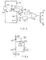
- Fig. 4 shows the constant current source 20 of Fig. 1 in greater detail.
- the constant current source 20 comprises a constant current source 121 known per se, one side of which is connected to the sliding contact 22 and the other side of which is connected to the pulse input of an operational amplifier 122.
- the output of operational amplifier 122 is connected to the negative input, the feed voltage connections are connected to the sliding contact 22 and to the negative input.
- the temperature-sensitive element 24 is connected between the output of the operational amplifier 122 and the sliding contact 21.
- a constant voltage source 123 is connected between the constant current source 121 and the sliding contact 21.
- the constant voltage source 123 is for example, a Zener diode.
- the current source 20 operates as follows:
- the constant current I flowing through the sliding contact 21 is made up of the constant current generated by the current source 121 and the current delivered by the output of the operational amplifier to the temperature-sensitive element 24.
- the input impedance of the operational amplifier 122 is very high.
- the current delivered by the constant current source 121 will therefore flow fully through the constant voltage source 123.
- the voltage at the junction of the constant current source 121 and the constant voltage source 123 will therefore not vary in time.
- the operational amplifier 122 is connected as a voltage follower. Since the input voltage at the positive input of the operational amplifier 122 does not change, neither will the output voltage thereof. Consequently, the voltage across the temperature-sensitive element 24 does not change.
- the output current of the operational amplifier 122 must change in order to maintain the voltage across the temperature-sensitive element 24 constant. Since the current I is the sum of current delivered by the constant current source 121, which is constant, and the current delivered by the output of the operational amplifier 122, this sum will change to a degree determined by the resistance changes of the temperature-sensitive element 24.
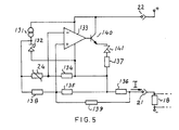
- Fig. 5 shows a developed circuit constructed according to the principle of Fig. 4 but with high sensitivity as a result of the use of a bridge circuit.
- the sliding contact 22 is connected to one side of the constant current source 131, the other side of the latter is connected to a first side of a Zener diode 132.
- the other side of the Zener diode 132 is connected to a feed voltage connection of an operational amplifier 133 and to one side of the resistors 134, 135, 136 and 137.
- the other side of the resistor 134 is connected to a temperature-dependent resistor 24 and to the negative input of the operational amplifier 133.
- the other side of the temperature-dependent resistor 24 is connected to the junction of the current source 131 and the Zener diode 132. This junction is also connected to one side of the resistor 138, the other side of which is connected to the positive input of the operational amplifier 133 and to the other side of the resistor 135.
- a resistor 139 is connected, on the one hand, to the junction between the resistors 135 and 138 and, on the other hand, to the other side of the resistor 136 and to the sliding contact 21.
- the output of operational amplifier 133 is connected to the base of transistor 140, the collector of which is connected to the sliding contact 22 and the emitter of which is connected to one side of a Zener diode 141, the other side of which is connected to the other side of the resistor 137.
- the resistance values of the resistors 134, 135 and 139 are equal to one another and are high with respect to the resistance values of the resistors 136 and 138 and of the temperature-dependent resistor 24.
- the amplification factor of the operational amplifier 133 is very high so that there is practically no voltage difference between the positive and negative inputs. It can be demonstrated that the magnitude of the current I flowing through the sliding contact 21 is directly proportional to the resistance value of the temperature-dependent resistance element 24 plus a constant value. The value of the current flowing through the sliding contact 21 can be determined in the manner described in connection with Fig. 1 so that the supply of energy to the heater element 11 can be controlled.
Landscapes
- Physics & Mathematics (AREA)
- General Physics & Mathematics (AREA)
- Control Of Temperature (AREA)
- Fixing For Electrophotography (AREA)
Claims (3)
Applications Claiming Priority (2)
| Application Number | Priority Date | Filing Date | Title |
|---|---|---|---|
| NL8104560A NL8104560A (nl) | 1981-10-07 | 1981-10-07 | Regelschakeling voor een warmtecontactfixeerinrichting. |
| NL8104560 | 1981-10-07 |
Publications (2)
| Publication Number | Publication Date |
|---|---|
| EP0076550A1 EP0076550A1 (fr) | 1983-04-13 |
| EP0076550B1 true EP0076550B1 (fr) | 1986-09-03 |
Family
ID=19838180
Family Applications (1)
| Application Number | Title | Priority Date | Filing Date |
|---|---|---|---|
| EP82201228A Expired EP0076550B1 (fr) | 1981-10-07 | 1982-10-01 | Circuit de contrôle pour un dispositif de fixage à chaleur |
Country Status (6)
| Country | Link |
|---|---|
| US (1) | US4471210A (fr) |
| EP (1) | EP0076550B1 (fr) |
| JP (1) | JPS5872180A (fr) |
| CA (1) | CA1185313A (fr) |
| DE (1) | DE3273041D1 (fr) |
| NL (1) | NL8104560A (fr) |
Families Citing this family (9)
| Publication number | Priority date | Publication date | Assignee | Title |
|---|---|---|---|---|
| US4512649A (en) * | 1983-10-11 | 1985-04-23 | Eastman Kodak Company | Fuser apparatus |
| EP0205669B1 (fr) * | 1985-06-18 | 1990-04-04 | Agfa-Gevaert N.V. | Circuit de chauffage électrique |
| US4778980A (en) * | 1986-10-06 | 1988-10-18 | Xerox Corporation | Instant-on fuser control |
| US5274423A (en) * | 1988-04-08 | 1993-12-28 | Minolta Camera Kabushiki Kaisha | Image forming apparatus having temperature control at a fixing unit |
| JPH07129025A (ja) * | 1993-10-29 | 1995-05-19 | Brother Ind Ltd | 熱定着装置 |
| JPH07129010A (ja) * | 1993-10-29 | 1995-05-19 | Brother Ind Ltd | 熱定着装置 |
| US6185546B1 (en) | 1995-10-04 | 2001-02-06 | Intel Corporation | Apparatus and method for providing secured communications |
| JPH09120230A (ja) * | 1995-10-25 | 1997-05-06 | Minolta Co Ltd | 定着装置 |
| WO2018232190A1 (fr) * | 2017-06-14 | 2018-12-20 | The University Of Vermont And State Agricultural College | Ancrage lesté de cathéter de dialyse péritonéale (pd) |
Family Cites Families (11)
| Publication number | Priority date | Publication date | Assignee | Title |
|---|---|---|---|---|
| US2526906A (en) * | 1947-10-24 | 1950-10-24 | Irving Seidman | Heating roller |
| US3290485A (en) * | 1964-01-06 | 1966-12-06 | Barber Colman Co | Temperature controlling device |
| US3500019A (en) * | 1968-01-18 | 1970-03-10 | Coltron Ind | Apparatus for developing temperature indicative signals from stationary or rotating heaters or drums and further for developing control signals from the temperature |
| GB1296036A (fr) * | 1968-11-27 | 1972-11-15 | ||
| US3674963A (en) * | 1970-10-19 | 1972-07-04 | Rosemount Inc | Measurement apparatus having non-contact electrical coupling to components on a moving surface |
| JPS4847389U (fr) * | 1971-10-06 | 1973-06-21 | ||
| JPS5110940A (en) * | 1974-07-18 | 1976-01-28 | Kip Kk | Idotaiheno kyudenbuno ijokenchikairo |
| JPS5339136A (en) * | 1976-09-22 | 1978-04-10 | Ricoh Co Ltd | Fixing temperature controlling method |
| US4114023A (en) * | 1976-10-22 | 1978-09-12 | Sys-Tec, Inc. | Heater control for rotary members |
| US4127764A (en) * | 1977-03-21 | 1978-11-28 | Sperry Rand Corporation | High efficiency fuser roll assembly for xerographic material |
| JPS5517101A (en) * | 1978-06-08 | 1980-02-06 | Olympus Optical Co Ltd | Recorder provided with heating means |
-
1981
- 1981-10-07 NL NL8104560A patent/NL8104560A/nl not_active Application Discontinuation
-
1982
- 1982-09-22 US US06/421,049 patent/US4471210A/en not_active Expired - Fee Related
- 1982-09-23 CA CA000412021A patent/CA1185313A/fr not_active Expired
- 1982-09-30 JP JP57172484A patent/JPS5872180A/ja active Pending
- 1982-10-01 DE DE8282201228T patent/DE3273041D1/de not_active Expired
- 1982-10-01 EP EP82201228A patent/EP0076550B1/fr not_active Expired
Also Published As
| Publication number | Publication date |
|---|---|
| EP0076550A1 (fr) | 1983-04-13 |
| NL8104560A (nl) | 1983-05-02 |
| DE3273041D1 (en) | 1986-10-09 |
| JPS5872180A (ja) | 1983-04-30 |
| US4471210A (en) | 1984-09-11 |
| CA1185313A (fr) | 1985-04-09 |
Similar Documents
| Publication | Publication Date | Title |
|---|---|---|
| US4053733A (en) | Temperature control device | |
| US4322970A (en) | Method and apparatus for controlling start-up of airflow measuring systems in automotive vehicles | |
| US4347740A (en) | Capacitive level sensing device | |
| US4546239A (en) | Non-continuous sensing apparatus for a temperature control | |
| US4086466A (en) | Automatic heater controller | |
| EP1279964B1 (fr) | Circuit de mesure de résistance | |
| EP0076550B1 (fr) | Circuit de contrôle pour un dispositif de fixage à chaleur | |
| JPS59202070A (ja) | センサ | |
| US5072614A (en) | Temperature compensating circuit | |
| GB2046919A (en) | Detecting the presence of a substance on a liquid surface | |
| US5150611A (en) | Flow sensor | |
| US4658120A (en) | Sensor device for use with cooking appliances | |
| US2887642A (en) | Damped servomotor system | |
| US3197699A (en) | Electrical moisture sensing device | |
| US3887864A (en) | Measured-value transducer with a compensating bridge circuit | |
| US4294116A (en) | Temperature detecting circuit | |
| USRE27596E (en) | Two-wire mv./v. transmitter | |
| JPH02284072A (ja) | 無線周波エネルギー検出回路 | |
| US4571991A (en) | Air flow measuring apparatus | |
| US3512013A (en) | Frequency sensing circuit | |
| US3831083A (en) | Conductivity and specific resistance measuring system | |
| SU1645902A1 (ru) | Способ определени скорости потока жидкости или газа | |
| SU851351A1 (ru) | Устройство дл автоматическогоОпРЕдЕлЕНи фАзОВыХ пЕРЕХОдОВКРиСТАлличЕСКиХ ВЕщЕСТВ | |
| JP2504834Y2 (ja) | イオン化式煙感知器 | |
| SU1157483A1 (ru) | Устройство дл контрол обрыва цепи |
Legal Events
| Date | Code | Title | Description |
|---|---|---|---|
| PUAI | Public reference made under article 153(3) epc to a published international application that has entered the european phase |
Free format text: ORIGINAL CODE: 0009012 |
|
| AK | Designated contracting states |
Designated state(s): DE FR GB IT NL |
|
| 17P | Request for examination filed |
Effective date: 19830924 |
|
| RAP1 | Party data changed (applicant data changed or rights of an application transferred) |
Owner name: OCE-NEDERLAND B.V. |
|
| GRAA | (expected) grant |
Free format text: ORIGINAL CODE: 0009210 |
|
| AK | Designated contracting states |
Kind code of ref document: B1 Designated state(s): DE FR GB IT NL |
|
| REF | Corresponds to: |
Ref document number: 3273041 Country of ref document: DE Date of ref document: 19861009 |
|
| ITF | It: translation for a ep patent filed | ||
| ET | Fr: translation filed | ||
| PLBE | No opposition filed within time limit |
Free format text: ORIGINAL CODE: 0009261 |
|
| STAA | Information on the status of an ep patent application or granted ep patent |
Free format text: STATUS: NO OPPOSITION FILED WITHIN TIME LIMIT |
|
| 26N | No opposition filed | ||
| PGFP | Annual fee paid to national office [announced via postgrant information from national office to epo] |
Ref country code: FR Payment date: 19900910 Year of fee payment: 9 |
|
| PGFP | Annual fee paid to national office [announced via postgrant information from national office to epo] |
Ref country code: GB Payment date: 19900912 Year of fee payment: 9 |
|
| PGFP | Annual fee paid to national office [announced via postgrant information from national office to epo] |
Ref country code: DE Payment date: 19900928 Year of fee payment: 9 |
|
| ITTA | It: last paid annual fee | ||
| PGFP | Annual fee paid to national office [announced via postgrant information from national office to epo] |
Ref country code: NL Payment date: 19901031 Year of fee payment: 9 |
|
| PG25 | Lapsed in a contracting state [announced via postgrant information from national office to epo] |
Ref country code: GB Effective date: 19911001 |
|
| PG25 | Lapsed in a contracting state [announced via postgrant information from national office to epo] |
Ref country code: NL Effective date: 19920501 |
|
| GBPC | Gb: european patent ceased through non-payment of renewal fee | ||
| NLV4 | Nl: lapsed or anulled due to non-payment of the annual fee | ||
| PG25 | Lapsed in a contracting state [announced via postgrant information from national office to epo] |
Ref country code: FR Effective date: 19920630 |
|
| PG25 | Lapsed in a contracting state [announced via postgrant information from national office to epo] |
Ref country code: DE Effective date: 19920701 |
|
| REG | Reference to a national code |
Ref country code: FR Ref legal event code: ST |