EP0077089A2 - Dispositif pour stocker ou transmettre des signaux d'image codés par transformation et pour regagner ces signaux d'image - Google Patents
Dispositif pour stocker ou transmettre des signaux d'image codés par transformation et pour regagner ces signaux d'image Download PDFInfo
- Publication number
- EP0077089A2 EP0077089A2 EP82201199A EP82201199A EP0077089A2 EP 0077089 A2 EP0077089 A2 EP 0077089A2 EP 82201199 A EP82201199 A EP 82201199A EP 82201199 A EP82201199 A EP 82201199A EP 0077089 A2 EP0077089 A2 EP 0077089A2
- Authority
- EP
- European Patent Office
- Prior art keywords
- values
- value
- transformation
- result
- coefficients
- Prior art date
- Legal status (The legal status is an assumption and is not a legal conclusion. Google has not performed a legal analysis and makes no representation as to the accuracy of the status listed.)
- Granted
Links
Images
Classifications
-
- H—ELECTRICITY
- H04—ELECTRIC COMMUNICATION TECHNIQUE
- H04N—PICTORIAL COMMUNICATION, e.g. TELEVISION
- H04N19/00—Methods or arrangements for coding, decoding, compressing or decompressing digital video signals
- H04N19/60—Methods or arrangements for coding, decoding, compressing or decompressing digital video signals using transform coding
Definitions
- the invention relates to an arrangement for storing or transmitting and for recovering image signals, in which coefficient values transformed from the image signals obtained by point-by-point scanning of an image are obtained in a transformation arrangement and these are converted into quantized values in a quantizer and the quantized values after storage or transfer decoded in a decoder and the decoded values are converted back in a reverse transformation arrangement into image signals which largely correspond to the original image signals, the transformation arrangement and the reverse transformation arrangement each combining two image signals or decoded values according to the transformation algorithm to form two result values and the result values of different combinations linked step by step.
- the number of information units can be reduced if the existing redundancy and possibly also the irrelevance are largely eliminated in an image. It is known, for example from the magazine "IEEE Transactions on Computers", Vol. Com-19, No. 1, February 1971, pages 50 to 62 or from the book by Pratt "Digital Image Processing", John Wiley & Sons 1978, Pages 232 to 278, for this reduction in the number of information units, ie for a data compression transform coding method with subsequent quantization. When quantizing The transformation coefficient is usually a non-linear characteristic curve that is based on the calculation of statistical averages.
- the value range of the individual transformed signals increases, as is briefly indicated by means of a Walsh-Hadamard transformation of two image signals A and B.
- the transformation of these two pixels yields the two coefficients If both image signals A and B had the maximum value, the coefficient F (1) has twice the value, ie the value range has been doubled. When the difference is formed, the sign doubles the value range. Since the image signals are processed in several stages during the transformation of a complete sub-image, whereby the value range is doubled in each case, the value range of the transformed signals is larger than the value range of the image signals, so that the data reduction due to the subsequent quantization is at least greatly reduced. A simple reduction in the range of values of the transformed signals or coefficients to the original range of values by appropriate standardization of the coefficients would lead to undesired rounding errors.
- the object of the invention is to provide an arrangement of the type mentioned at the outset which avoids an enlargement of the value range of the values to be stored or of the values to be transferred compared to the original value range of the image signals, at the same time being a favorable one Quantization is possible.
- This object is achieved according to the invention in that the transformation arrangement has at least one additional logic element which receives the carry signal of the one result value which arises with each logic operation and the sign signal of the other result value and generates an auxiliary signal at the output which is fed to the one result value as the most significant bit, the least significant bit of this result value and the carry signal and the sign signal of the result values being suppressed for storage or transmission.
- the invention uses i.a. the fact that the results of summing and subtracting two numbers must always be both even or both odd so that the last bit of one of the two result values can be omitted without losing information.
- the combination of carry and sign of the result values does not actually result in any ambiguity, but the result values can be clearly converted back during the back transformation, as will be explained later.
- the result values since the result values only have the same value range as the linked values for each link, the values to be quantized have the same value range as the original image signals. The occurrence of redundancy generated by the transformation itself is thus avoided, so that an optimal data compression can be achieved together with a quantization.
- the transformation arrangement comprises the two result values of each combination of the sum and the difference between two values
- the additional logic element is an exclusive OR gate and that the reverse transformation arrangement each links a first decoded value containing the least significant bit with a second decoded value still containing the auxiliary signal and thereby the bits of the first value by one digit shifts to the lower value and assigns the value "0" to the previous bit position of highest value and processes the bit of the lowest value as a carry signal for the lowest position in the summation.
- a further embodiment of the invention is characterized in that the quantizer works only in the value range of the original image signals with quantization characteristics which are symmetrical or, in many cases, symmetrical with respect to coefficient values that are equidistant from one another. This also results in better maintenance of pronounced edge structures in the image, as will also be explained later.
- the image signals are supplied via the input 1.
- These image signals can be supplied directly from the image scanner, such as a television recording device, but it is generally more expedient to temporarily store the image signals of an image in a memory, since a larger image is generally transformed and transmitted in successive, usually square sub-images. This possibility is not shown, however, since it is not relevant to the invention.
- the image signals supplied via line 1 are transformed in transformation arrangement 2 in accordance with the desired transformation algorithm under control of control unit 6, and the transformed values or coefficients are supplied via line 3 to quantizer 4, which is also controlled by control unit 6 becomes.
- the quantized values are fed to the transmission link 10.
- a memory can also be used.
- the values transmitted or read out from the memory are fed on the receiving side to a decoder 14, where the individual quantized values are assigned an average coefficient value which belongs to the quantization level indicated by this value.
- the decoded coefficient values are fed via line 13 to the reverse transformation arrangement 12, so that essentially the original image signals supplied to the input 1 appear at the output 15.
- the decoder 14 and the inverse transformation arrangement 12 are controlled by the control unit 16, which also contains the characteristic curve memory for the assignment of input values to coefficient values in the decoder 14, just as the control unit 6 on the transmission side contains the characteristic curve memory for the quantizer 4.
- the general structure of a transformation arrangement 2, a quantizer 4, a decoder 14 and a reverse transformation arrangement 12 is known in principle, the structure of the transformation arrangements also being able to be different for a given transformation algorithm.
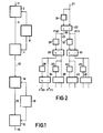
- FIG. 2 An arrangement for carrying out a Walsh-Hadamard transformation in this way is shown in FIG. 2. Every second signal of the signals supplied at the input 21 is temporarily stored in the buffer 24, so that two successive signal values are present at the input of the computing unit 22. In the Walsh-Hadamard transformation, the computing unit 22 forms the sum and the difference of these two values and outputs the results at the two outputs 23 and 25 designated accordingly. These initial values correspond to the coefficients F (0) and F (1) given in equation (3), which are given in FIG. 2.
- the first value of the output values at the output 23 is temporarily stored in the buffer memory 28 and then fed to the one input of the computing unit 26, while the second output value of the output 23 is fed directly to the other input of the computing unit 26.
- the corresponding process is carried out with the output values at the output 25, of which the first value is temporarily stored in the memory 32 and then fed in parallel to the computing unit 30 together with the respective second value.
- the computing unit 26 and 30 are constructed in exactly the same way as the computing unit 22 and also the following computing units 34, 38, 42 and 46.
- Output values then appear at the outputs of the computing units 26 and 30, which correspond to the coefficients of a sub-image consisting of 2x2 pixels. These output values are also alternately fed via the intermediate memories 36, 40, 44 or 48 or directly to the computing units 34, 38, 42 and 46. These computing units generate the coefficients F "(0), F" (1) ... of a sub-picture with 4x2 pixels at the outputs.
- This arrangement can be continued as desired that correspondingly large sub-images are transformed and the coefficient values are output in parallel.
- the arithmetic unit 22 since the arithmetic unit 22 only outputs two output signals in parallel for every second image signal supplied, and this applies to all subsequent arithmetic units, it may be expedient to temporarily store all the output signals of the arithmetic unit 22 for a sub-image of a predetermined size and, after processing all the image signals of this sub-image, the input of the arithmetic unit 22 switch to the output of this buffer and repeat this process for each stage according to the specified sub-picture size.
- a special control with a special address generator is necessary, but there is the advantage that only a single computing unit is required.
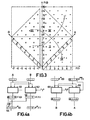
- the sloping coordinates A and B indicate the possible input values of an arithmetic unit.
- the Walsh-Hadamard coefficients F (0) and F (1) formed from this are given in the perpendicular coordinate system. From this it can be seen that the coefficients F (0) and F (1) each have a value range of 2 G if the value range of the signals A and B supplied is equal to G.
- the enlargement of the value range arises from the fact that a carry-over can occur when the sum is formed and a negative sign can occur when the difference is formed.
- the value combinations of the coefficients F (0) and F (1) indicated by crosses fulfill an uncertainty principle of the following form:
- This latter relationship describes the arrangement of the actually occurring combinations of values, denoted by crosses, of the two coefficients F (0) and F (1) in the form of a square standing on the top, so that the dashed outer square represents the total number of representable combinations of values includes, the areas in the corners are not occupied, so that the number of combinations of values that can be represented include a range that corresponds to a doubling of the range of actually occurring value combinations of the coefficients F (0) and F (1).
- FIG. 4a A circuit arrangement which realizes such a mapping of the coefficients and which can be used for each of the computing units 22, 26, 30 etc. in FIG. 2 is shown in FIG. 4a.
- the two signals A and B supplied are assumed to be four-bit dual words, which is indicated by the block with four boxes in the signal path. These two signals are fed to both an adding unit 60 and a subtracting unit 62, the subtracting unit 62 being supplied with a carry signal with the value "1" in order to obtain the corresponding difference representation in two's complement.
- the output values of the two units 60 and 62 represent the coefficients F (0) and F (1), which are represented by dual words with five bits. With the coefficient F (0), the bit Ü indicates the Instead of the highest value, the carry and for the coefficient F (1) the bit VZ at the position of the highest value, the sign.
- the reverse transformation unit 12 in FIG. 1 is constructed similarly to the transformation unit 2; when using the Walsh-Hadamard transformation, the two arrangements are even identical. Finally, by step-by-step processing of two coefficients, apart from the quantization errors, the original image data is generated. When using the modified coefficients that are generated by the arrangement according to FIG. 4a, however, a modified inverse transformation is also necessary.
- the values that are linked in the individual areas are shown in Table 1.
- the factor 1/2 for the total coefficient F * (0) results from the fact that the The least significant bit is omitted.
- the factor 1/2 also results from the fact that the least significant bit is separated and processed differently from the other bits, as subsequently based on a technical implementation in the form of a computing unit for performing the arithmetic operation described above is explained.
- Such a computing unit is shown in Fig. 4b.
- This also contains an adding unit 68 and a subtracting unit 66, to each of which two decoded coefficients or intermediate values are fed in parallel, of which the one coefficient, which is designated here with F * (0), was last created during the transformation from an addition and the other coefficient, which is designated here with F ** (1), was last created during the transformation from a subtraction.
- This latter coefficient is obtained from the coefficient F * (1) in that it has been extended by one bit in the most significant position, this additional bit having the value "0".
- each result value can also be interpreted as a modified coefficient of the next stage and in exactly the same way during the reverse transformation Be processed further. Exceeding the word length is thus avoided both during the transformation and during the reverse transformation, so that the computing units only have to be designed for the smallest possible word length. Furthermore, since the coefficients to be finally quantized have the same word length as that of the supplied image signals, there is a significant simplification and a better effectiveness of the quantization and thus also the data reduction.
- the first advantage arises from the fact that the quantizer only has to process positive values for the difference coefficient.
- the quantizer only has to process positive values for the difference coefficient.
- the number of reduced information units is essentially given by the fine-level quantization.
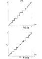
- the quantization curve according to Fig. 5a due to the required symmetry, an almost double-exact quantization in half of the original range is required, so that in this case there is only a small gain for data compression with a constant quantization error if this occurs with the corresponding quantization of the already mentioned characteristic curve symmetrical to the zero point is compared.
- the modified coefficients result in a gain of a factor of 2, since the same number of quantization stages is used only in half of the original range. This results in a profit with a factor between 1 and 2 for the modified coefficients.
- a second advantage results from the fact that, due to the symmetrical, non-linear quantization characteristic, large values of the difference coefficient are more precisely shown advertises so that even pronounced edge structures, ie steep transitions in the image, are better reproduced than with conventional methods.
- a Walsh-Hadamard transformation of a sub-image with four pixels A, B, C and D which can be carried out by applying the basic transformation twice according to equations (1) and (4). If the modified values according to Table 1 are formed each time the basic transformation is carried out, which does not result in an increase in the word length, the following four coefficients result:
- the sum coefficient F * (0) is in turn transmitted unchanged.
- the coefficient F * (1) it must be taken into account that in the first transformation step the most significant bit of the sums A + B or C + D representing the carry is changed by the equivalence function according to Table 1 and the bit of the lowest value is separated, what needs to be considered in the subsequent subtraction.
- the actual subtraction in the second transformation step then in turn requires a symmetrical characteristic curve according to FIG. 5a, so that the double-symmetrical characteristic curve shown in FIG. 5b is produced overall.
- the same quantization characteristic results for the coefficient F * (2).
- the coefficient F * (3) which arises from a two-fold difference formation, in turn only requires the single-symmetrical characteristic curve according to FIG. 5a.
- the formation of the modified coefficients results in a gain for the quantizer, since the quantizer only has to process coefficients with a value range equal to that of the original image signals.
- edge structures in the image are also better reproduced due to the symmetry of the quantization characteristic.
Landscapes
- Engineering & Computer Science (AREA)
- Multimedia (AREA)
- Signal Processing (AREA)
- Compression Or Coding Systems Of Tv Signals (AREA)
- Compression, Expansion, Code Conversion, And Decoders (AREA)
Applications Claiming Priority (2)
| Application Number | Priority Date | Filing Date | Title |
|---|---|---|---|
| DE19813138816 DE3138816A1 (de) | 1981-09-30 | 1981-09-30 | Anordnung zum speichern oder uebertragen und zum rueckgewinnen von bildsignalen |
| DE3138816 | 1981-09-30 |
Publications (3)
| Publication Number | Publication Date |
|---|---|
| EP0077089A2 true EP0077089A2 (fr) | 1983-04-20 |
| EP0077089A3 EP0077089A3 (en) | 1986-06-04 |
| EP0077089B1 EP0077089B1 (fr) | 1988-09-07 |
Family
ID=6142984
Family Applications (1)
| Application Number | Title | Priority Date | Filing Date |
|---|---|---|---|
| EP82201199A Expired EP0077089B1 (fr) | 1981-09-30 | 1982-09-24 | Dispositif pour stocker ou transmettre des signaux d'image codés par transformation et pour regagner ces signaux d'image |
Country Status (4)
| Country | Link |
|---|---|
| US (1) | US4463377A (fr) |
| EP (1) | EP0077089B1 (fr) |
| JP (1) | JPS5871768A (fr) |
| DE (2) | DE3138816A1 (fr) |
Cited By (3)
| Publication number | Priority date | Publication date | Assignee | Title |
|---|---|---|---|---|
| EP0118754A3 (en) * | 1983-02-11 | 1985-11-13 | Siemens Aktiengesellschaft | Method of digitally transmitting television pictures |
| EP0237928A3 (en) * | 1986-03-18 | 1989-03-29 | Deutsche Thomson-Brandt Gmbh | Method for correcting blockwise transmitted discrete values |
| US5805293A (en) * | 1995-01-30 | 1998-09-08 | Nec Corporation | Hadamard transform coding/decoding method and apparatus for image signals |
Families Citing this family (12)
| Publication number | Priority date | Publication date | Assignee | Title |
|---|---|---|---|---|
| NL8105799A (nl) * | 1981-12-23 | 1983-07-18 | Philips Nv | Stelsel voor het overdragen van een televisiebeeldinformatie middels een beeldbloksgewijze tegen fouten beschermende kode, beeldvormer met inrichting voor het genereren van zo een bloksgewijs beschermende kode, en weergeeftoestel voor het onder dekodering van de kode weergeven van het televisiebeeld. |
| US4621337A (en) * | 1983-08-11 | 1986-11-04 | Eastman Kodak Company | Transformation circuit for implementing a collapsed Walsh-Hadamard transform |
| US4673988A (en) * | 1985-04-22 | 1987-06-16 | E.I. Du Pont De Nemours And Company | Electronic mosaic imaging process |
| DE3728444A1 (de) * | 1987-08-26 | 1989-03-09 | Thomson Brandt Gmbh | Verfahren und schaltungsanordnung zur verbesserung der aufloesung von digitalen signalen |
| TW224553B (en) * | 1993-03-01 | 1994-06-01 | Sony Co Ltd | Method and apparatus for inverse discrete consine transform and coding/decoding of moving picture |
| US5412429A (en) * | 1993-03-11 | 1995-05-02 | The United States Of America As Represented By The Administrator Of The National Aeronautics And Space Administration | Picture data compression coder using subband/transform coding with a Lempel-Ziv-based coder |
| DE4423226C1 (de) * | 1994-07-01 | 1995-08-24 | Harris Corp | Digitaler Dekoder für Videosignale und Verfahren zur digitalen Dekodierung von Videosignalen |
| JP3058028B2 (ja) * | 1994-10-31 | 2000-07-04 | 三菱電機株式会社 | 画像符号化データ再符号化装置 |
| US5856935A (en) * | 1996-05-08 | 1999-01-05 | Motorola, Inc. | Fast hadamard transform within a code division, multiple access communication system |
| US7200629B2 (en) * | 2002-01-04 | 2007-04-03 | Infineon Technologies Ag | Apparatus and method for Fast Hadamard Transforms |
| US9008184B2 (en) | 2012-01-20 | 2015-04-14 | Blackberry Limited | Multiple sign bit hiding within a transform unit |
| US9450601B1 (en) * | 2015-04-02 | 2016-09-20 | Microsoft Technology Licensing, Llc | Continuous rounding of differing bit lengths |
Family Cites Families (8)
| Publication number | Priority date | Publication date | Assignee | Title |
|---|---|---|---|---|
| US3775602A (en) * | 1972-06-29 | 1973-11-27 | Us Air Force | Real time walsh-hadamard transformation of two-dimensional discrete pictures |
| FR2262350B1 (fr) * | 1974-02-25 | 1976-12-03 | France Etat | |
| JPS5515147B2 (fr) * | 1974-05-02 | 1980-04-21 | ||
| US4055756A (en) * | 1975-02-03 | 1977-10-25 | Societe Anonyme De Telecommunications | Image coder-decoder using a matrix transform with weighted contribution of several points of the image to the formation of one point of the transform |
| US3956619A (en) * | 1975-03-31 | 1976-05-11 | General Electric Company | Pipeline walsh-hadamard transformations |
| US3981443A (en) * | 1975-09-10 | 1976-09-21 | Northrop Corporation | Class of transform digital processors for compression of multidimensional data |
| DE2625973C3 (de) * | 1976-06-10 | 1981-12-24 | Philips Patentverwaltung Gmbh, 2000 Hamburg | Verfahren und Anordnung zur redundanzvermindernden Transformation von Bildern |
| US4261043A (en) * | 1979-08-24 | 1981-04-07 | Northrop Corporation | Coefficient extrapolator for the Haar, Walsh, and Hadamard domains |
-
1981
- 1981-09-30 DE DE19813138816 patent/DE3138816A1/de not_active Withdrawn
-
1982
- 1982-09-22 US US06/421,610 patent/US4463377A/en not_active Expired - Fee Related
- 1982-09-24 EP EP82201199A patent/EP0077089B1/fr not_active Expired
- 1982-09-24 DE DE8282201199T patent/DE3279023D1/de not_active Expired
- 1982-09-30 JP JP57169946A patent/JPS5871768A/ja active Granted
Cited By (3)
| Publication number | Priority date | Publication date | Assignee | Title |
|---|---|---|---|---|
| EP0118754A3 (en) * | 1983-02-11 | 1985-11-13 | Siemens Aktiengesellschaft | Method of digitally transmitting television pictures |
| EP0237928A3 (en) * | 1986-03-18 | 1989-03-29 | Deutsche Thomson-Brandt Gmbh | Method for correcting blockwise transmitted discrete values |
| US5805293A (en) * | 1995-01-30 | 1998-09-08 | Nec Corporation | Hadamard transform coding/decoding method and apparatus for image signals |
Also Published As
| Publication number | Publication date |
|---|---|
| EP0077089A3 (en) | 1986-06-04 |
| JPS5871768A (ja) | 1983-04-28 |
| DE3138816A1 (de) | 1983-04-14 |
| US4463377A (en) | 1984-07-31 |
| DE3279023D1 (en) | 1988-10-13 |
| EP0077089B1 (fr) | 1988-09-07 |
| JPH0262993B2 (fr) | 1990-12-27 |
Similar Documents
| Publication | Publication Date | Title |
|---|---|---|
| DE2640140C2 (de) | Verfahren und Anordnung zur redundanzvermindernden Bildcodierung | |
| DE69232597T2 (de) | Kodierungsverfahren | |
| DE2625973C3 (de) | Verfahren und Anordnung zur redundanzvermindernden Transformation von Bildern | |
| EP0077089B1 (fr) | Dispositif pour stocker ou transmettre des signaux d'image codés par transformation et pour regagner ces signaux d'image | |
| DE2640157C2 (de) | Verfahren und Anordnung zum redundanzvermindernden Codieren von Bildern | |
| DE69606139T2 (de) | Verfahren und vorrichtung zur rauschunterdrückung in komprimierten bilddaten | |
| DE69720559T2 (de) | Methode zur Bildkodierung mit Kodes variabler Länge | |
| DE69425847T2 (de) | Rechner für die inverse diskrete Cosinus-Transformation | |
| DE69029976T2 (de) | Verfahren und Einrichtung zur Bilddatenkompression durch mathematische Transformation | |
| DE69126804T2 (de) | Kompressionssystem von bewegten Bilddaten | |
| DE68926676T2 (de) | Verfahren und gerät zur statistischen kodierung von digitalen daten | |
| DE69229085T2 (de) | System zur Bildverarbeitung | |
| DE3708288A1 (de) | Verfahren zur verringerung der datenmenge bei der bildkodierung | |
| DE69424923T2 (de) | Verfahren und Anordnung zur Bearbeitung eines dekodierten Bildsignals mit Verzerrung | |
| DE68908941T2 (de) | Verfahren zur Kodierung und Dekodierung von Blockinformationen und Vorrichtung dazu. | |
| EP0304836A2 (fr) | Procédé et circuit relatifs à la résolution de signaux numériques | |
| DE3545106C2 (fr) | ||
| DE69424377T2 (de) | Rechner für die diskrete Cosinus-Transformation | |
| DE3424078A1 (de) | Dezimalmultiplikations-einrichtung | |
| EP0346750B1 (fr) | Dispositif pour le codage par MICD avec un débit de données élevé | |
| EP1110407B1 (fr) | Procede et dispositif pour le codage et le decodage d'une image numerisee faisant appel a un vecteur de deplacement total | |
| EP0148528B1 (fr) | Méthode et circuit pour augmenter la résolution d'un signal digital dépendant du temps | |
| EP1034511B1 (fr) | Procede de conversion de donnees numeriques comprises dans une trame d'une premiere definition en donnees cibles numeriques d'une seconde definition | |
| DE3417262C2 (fr) | ||
| DE3124550C2 (fr) |
Legal Events
| Date | Code | Title | Description |
|---|---|---|---|
| PUAI | Public reference made under article 153(3) epc to a published international application that has entered the european phase |
Free format text: ORIGINAL CODE: 0009012 |
|
| 17P | Request for examination filed |
Effective date: 19820924 |
|
| AK | Designated contracting states |
Designated state(s): DE FR GB |
|
| PUAL | Search report despatched |
Free format text: ORIGINAL CODE: 0009013 |
|
| AK | Designated contracting states |
Kind code of ref document: A3 Designated state(s): DE FR GB |
|
| RAP1 | Party data changed (applicant data changed or rights of an application transferred) |
Owner name: N.V. PHILIPS' GLOEILAMPENFABRIEKEN Owner name: PHILIPS PATENTVERWALTUNG GMBH |
|
| 17Q | First examination report despatched |
Effective date: 19871111 |
|
| GRAA | (expected) grant |
Free format text: ORIGINAL CODE: 0009210 |
|
| AK | Designated contracting states |
Kind code of ref document: B1 Designated state(s): DE FR GB |
|
| REF | Corresponds to: |
Ref document number: 3279023 Country of ref document: DE Date of ref document: 19881013 |
|
| ET | Fr: translation filed | ||
| GBT | Gb: translation of ep patent filed (gb section 77(6)(a)/1977) | ||
| PLBE | No opposition filed within time limit |
Free format text: ORIGINAL CODE: 0009261 |
|
| STAA | Information on the status of an ep patent application or granted ep patent |
Free format text: STATUS: NO OPPOSITION FILED WITHIN TIME LIMIT |
|
| 26N | No opposition filed | ||
| PGFP | Annual fee paid to national office [announced via postgrant information from national office to epo] |
Ref country code: DE Payment date: 19891129 Year of fee payment: 8 |
|
| PGFP | Annual fee paid to national office [announced via postgrant information from national office to epo] |
Ref country code: GB Payment date: 19900831 Year of fee payment: 9 |
|
| PGFP | Annual fee paid to national office [announced via postgrant information from national office to epo] |
Ref country code: FR Payment date: 19900920 Year of fee payment: 9 |
|
| PG25 | Lapsed in a contracting state [announced via postgrant information from national office to epo] |
Ref country code: DE Effective date: 19910601 |
|
| PG25 | Lapsed in a contracting state [announced via postgrant information from national office to epo] |
Ref country code: GB Effective date: 19910924 |
|
| GBPC | Gb: european patent ceased through non-payment of renewal fee | ||
| PG25 | Lapsed in a contracting state [announced via postgrant information from national office to epo] |
Ref country code: FR Effective date: 19920529 |
|
| REG | Reference to a national code |
Ref country code: FR Ref legal event code: ST |