EP0077214B1 - Compresseur à volutes imbriquées avec rendement élevé - Google Patents
Compresseur à volutes imbriquées avec rendement élevé Download PDFInfo
- Publication number
- EP0077214B1 EP0077214B1 EP82305428A EP82305428A EP0077214B1 EP 0077214 B1 EP0077214 B1 EP 0077214B1 EP 82305428 A EP82305428 A EP 82305428A EP 82305428 A EP82305428 A EP 82305428A EP 0077214 B1 EP0077214 B1 EP 0077214B1
- Authority
- EP
- European Patent Office
- Prior art keywords
- wrap
- end plate
- scroll
- transition
- spiral
- Prior art date
- Legal status (The legal status is an assumption and is not a legal conclusion. Google has not performed a legal analysis and makes no representation as to the accuracy of the status listed.)
- Expired
Links
- 239000012530 fluid Substances 0.000 claims description 90
- 230000007704 transition Effects 0.000 claims description 41
- 230000007246 mechanism Effects 0.000 claims description 5
- 230000000694 effects Effects 0.000 claims description 4
- 230000006835 compression Effects 0.000 description 24
- 238000007906 compression Methods 0.000 description 24
- 238000005192 partition Methods 0.000 description 8
- 235000014676 Phragmites communis Nutrition 0.000 description 5
- 238000007789 sealing Methods 0.000 description 5
- 230000008859 change Effects 0.000 description 4
- 238000006073 displacement reaction Methods 0.000 description 4
- 230000002093 peripheral effect Effects 0.000 description 3
- 230000004323 axial length Effects 0.000 description 2
- 238000010586 diagram Methods 0.000 description 2
- 238000011038 discontinuous diafiltration by volume reduction Methods 0.000 description 2
- 230000013011 mating Effects 0.000 description 2
- 230000004048 modification Effects 0.000 description 2
- 238000012986 modification Methods 0.000 description 2
- 230000009467 reduction Effects 0.000 description 2
- 239000003507 refrigerant Substances 0.000 description 2
- 230000000717 retained effect Effects 0.000 description 2
- 238000010276 construction Methods 0.000 description 1
- 230000007423 decrease Effects 0.000 description 1
- 238000007373 indentation Methods 0.000 description 1
Images




Classifications
-
- F—MECHANICAL ENGINEERING; LIGHTING; HEATING; WEAPONS; BLASTING
- F04—POSITIVE - DISPLACEMENT MACHINES FOR LIQUIDS; PUMPS FOR LIQUIDS OR ELASTIC FLUIDS
- F04C—ROTARY-PISTON, OR OSCILLATING-PISTON, POSITIVE-DISPLACEMENT MACHINES FOR LIQUIDS; ROTARY-PISTON, OR OSCILLATING-PISTON, POSITIVE-DISPLACEMENT PUMPS
- F04C18/00—Rotary-piston pumps specially adapted for elastic fluids
- F04C18/02—Rotary-piston pumps specially adapted for elastic fluids of arcuate-engagement type, i.e. with circular translatory movement of co-operating members, each member having the same number of teeth or tooth-equivalents
- F04C18/0207—Rotary-piston pumps specially adapted for elastic fluids of arcuate-engagement type, i.e. with circular translatory movement of co-operating members, each member having the same number of teeth or tooth-equivalents both members having co-operating elements in spiral form
- F04C18/0246—Details concerning the involute wraps or their base, e.g. geometry
- F04C18/0269—Details concerning the involute wraps
- F04C18/0276—Different wall heights
Definitions
- This invention relates to a fluid displacement apparatus of the scroll type, such as a compressor.
- Scroll type fluid displacement apparatus are well known in the prior art.
- U.S. Patent No. 801.182 discloses a scroll type fluid displacement apparatus including two scroll members, each having a circular end plate and a spiroidal or involute spiral element. These scroll members are maintained angularly and radially offset so that both spiral elements interfit to make a plurality of line contacts between the spiral curved surfaces to thereby seal off and define at least one pair of fluid pockets.
- the relative orbital motion of the two scroll members shifts the line contacts along the spiral curved surfaces and, therefore, the fluid pockets change in volume.
- the volume of the fluid pockets increases or decreases depending on the direction of the orbiting motion. Therefore, the scroll type fluid displacement apparatus is applicable to compress, expand or pump fluids.
- a scroll type compressor including a housing having a fluid inlet port and a fluid outlet port, a fixed scroll fixedly disposed relative to said housing and having a circular end plate from which a first spiral wrap extends axially into an operative interior area of said housing, an orbiting scroll having a circular end plate from which a second spiral wrap axially extends, said first and second spiral wraps interfitting at an angular and radial offset to make a plurality of line contacts to define at least one pair of sealed off fluid pockets within said operative interior area, a driving mechanism operatively connected to said orbiting scroll to effect orbital motion of said orbiting scroll so that the volume of the fluid pockets changes during the orbital motion of said orbiting scroll, characterised by a transition portion on the spiral wrap of one of said scrolls, said transition portion defining an inner wrap portion extending from said transition portion toward the inner end of the spiral wrap, and defining an outer wrap portion extending from said transition portion toward the outer end of the spiral wrap, said inner wrap portion having
- One embodiment of the invention includes a housing and a pair of scroll members.
- One of the scroll members is fixedly disposed relative to the housing and has an end plate from which a first spiral wrap extends axially into the interior of the housing.
- the other scroll member is movably disposed for non-rotative orbital movement within interior of the housing and has an end plate from which a second spiral wrap extends.
- the first and second spiral wraps interfit at an angular and radial offsetto make a plurality of line contacts to define at least one pair of fluid pockets.
- a driving mechanism is operatively connected to the orbiting scroll member to effect its orbital motion, whereby the fluid pockets move inwardly and change in volume.
- a transition portion of the spiral wrap of one of the scrolls defines an inner wrap portion (extending inwardly of the transition portion) and an outer wrap portion (extending outwardly of the transition portion).
- the inner wrap portion has a greater axial length or height than the outer wrap portion.
- a stepped portion on the end plate of the other scroll member is generally in registry with the transition 'portion.
- the stepped portion defines an inner end plate portion (extending within the wrap affixed to its end plate from the stepped portion toward the center of the scroll), and an outer end plate portion (extending within the wrap toward the periphery of the scroll).
- the inner end plate portion is deeper than the outer end plate portion to accommodate the higher inner wrap portion therein.
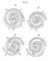
- Figures 1a-1d schematically illustrate the relative movement of interfitting spiral elements to compress the fluid.
- Figure 2 diagrammatically illustrates the compression cycle in each of the fluid pockets.
- Figures 1a1d may be considered to be end views of a compressor wherein the end plates are removed and only the spiral elements are shown.
- Two spiral elements 1 and 2 are angularly and radially offset and interfit with one another.
- the orbiting spiral element 1 and fixed spiral element 2 make four line contacts as shown at four points A, B, C, D.
- a pair of fluid pockets 3a and 3b are defined between line contacts D-C and line contacts A-B, as shown by the dotted regions.
- the fluid pockets 3a and 3b are defined not only by the wall of spiral elements 1 and 2 but also by the end plates from which these spiral elements extend.
- both pockets 3a and 3b merge at the center portion 5 and are completely connected to one another to form a single pocket.
- the volume of the connected single pocket is further reduced by further revolution of 90° as shown in Figures 1b, 1c and 1d.
- outer spaces which open in the state shown in Figure 1b change as shown in Figures 1c, 1d and 1a, to form new sealed off fluid pockets in which fluid is newly enclosed.
- Figure 2 shows the relationship of fluid pressure in the fluid pocket to crank angle, and shows that one compression cycle is completed at a crank angle of 4n, in this case.
- the compression cycle begins ( Figure 1 a) when the fluid pockets are sealed, i.e., with the outer end of each spiral element in contact with the opposite spiral element, the suction phase having finished.
- the state of fluid pressure in a fluid pocket is shown at point h in Figure 2.
- the volume of the fluid pocket is reduced and fluid is compressed by the revolution of the orbiting scroll until the crank angle reaches 2n, which state is shown by the point I in Figure 2.
- the pair of fluid pockets are connected to one another and simultaneously are connected to the space filled with high pressure, which is left undischarged at the center of both spiral elements.
- the pressure changes in one fluid pocket due to the orbital motion is shown by points h, I, m, n, o and p.
- the pressure differential between the adjacent fluid. pockets of this compressor will be smaller. Therefore, the amount of fluid leakage from the higher pressure fluid pockets to the lower pressure pockets across the line contacts between the spiral curved surfaces is reduced to thereby improve the volumetric efficiency.
- the swept volume of the compressor advantageously is made larger.
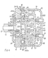
- the compressor includes a compressor housing 10 having a front end plate II and a cup shaped casing 12 fastened to an end surface of front end plate 11.
- An opening 111 is formed on the center of front end plate 11 for supporting a drive shaft 13.
- An annular projection 112, concentric with opening 111, is formed on the rear end surface of front end plate 11.
- Annular projection 112 fits into an inner wall of the opening of cup shaped casing 12.
- Cup shaped casing 12 is fixed on the rear end surface of front end plate 11 by suitable fasteners, such as bolts and nuts (not shown), so that the opening of cup shaped casing 12 is covered by front end plate 11.
- An O-ring 14 is placed between the outer peripheral surface of annular projection 112 and the inner wall of cup shaped casing 12 to seal the mating surfaces between the front end plate 11 and cup shaped casing 12.
- Drive shaft 13 is formed with a disk-shaped rotor 15 at its inner end portion. Disk shaped rotor 15 is rotatably supported by front end plate 11 through a bearing 16 located within opening 111 of front end plate 11. Front end plate 11 has an annular sleeve 18 projecing from the front end surface thereof. This sleeve 18 surrounds drive shaft 13 to define a shaft seal cavity. A shaft seal assembly 20 is assembled on drive shaft 13 within the shaft seal cavity. As shown in Figure 4, sleeve 18 is attached to the front end surface of front end plate 11 by screws 19. Alternatively, sleeve 18 may be formed integral with front end plate 11.
- drive shaft 13 which extends from sleeve 18 is connected to a rotation transmitting device, for example, a magnetic clutch which may be disposed on the outer peripheral surface of sleeve 18 for transmitting rotary movement to drive shaft 13.
- a rotation transmitting device for example, a magnetic clutch which may be disposed on the outer peripheral surface of sleeve 18 for transmitting rotary movement to drive shaft 13.
- drive shaft 13 is driven by an external power source, for example, the engine of a vehicle, through the rotation transmitting device.
- a number of elements are located within the inner chamber of cup shaped casing 12 including a fixed scroll 21, an orbiting scroll 22, a driving mechanism 23 for orbiting scroll 22 and a rotation preventing/thrust bearing device 24 formed between the inner wall of cup shaped casing 12 and the rear end surface of front end plate 11.
- Fixed scroll 21 includes circular end plate 211, wrap or spiral element 212 affixed to or extending from one end surface of circular end plate 211, and an annular partition wall 213 axially projecting from the end surface of circular end plate 211 on the side opposite spiral element 212.
- Annular partition wall 213 is formed with a plurality of equiangularly spaced threaded bosses 214 for securing scroll 21 to casing 12.
- Partition wall 213 and bosses 214 mate with annular partition wall 122 and hollow bosses 123 on the inner surface of end plate portion 121, and are secured to casing 12 by a plurality of bolts 25 (two bolts 25 are shown in Figure 4).
- a seal ring 26 is placed under the head of each bolt 25 to prevent fluid leakage past bolts 25.
- Circular end plate 211 of fixed scroll 21 thus partitions the inner chamber of cup shaped casing 12 into a discharge chamber 28 having partition walls 213, 122, and suction chamber 29, in which spiral element 212 of fixed scroll 21 is located.
- a sealing member 27 is disposed within a circumferential groove 215 on circular end plate 211 for sealing the outer peripheral surface of circular end plate 211 to the inner wall of cup shaped casing 12. Since partition walls 213, 122 are located within discharge chamber 28, discharge chamber 28 is partitioned into central space 281 and outer space 282, and both spaces 281 and 282 are connected to one another through a hole 217 formed in partition walls 213, 122.
- Orbiting scroll 22 which is disposed in suction chamber 29, includes a circular end plate 221 and wrap or spiral element 222 affixed to and extending from one end surface of circular end plate 221.
- the spiral elements 212 and 222 interfit at an angular offset of 180° and a predetermined radial offset.
- the spiral elements define at least one pair of fluid pockets between their interfitting surfaces.
- Axial sealing elements 217, 227 are retained in end grooves 218, 228 of spiral elements 212, 222 to effect axial sealing with end plates 22, 21.
- Orbiting scroll 22 is rotatably supported on a bushing 231 through a bearing such as radial bearing 232.
- Bushing 231 is connected to a crank pin 233 eccentrically projecting from the end surface of disk-shaped rotor 15. Orbiting scroll 22 is thus rotatably supported on crank pin 233. Therefore, orbiting scroll is moved by the rotation of drive shaft 13.
- Rotation preventing/thrust bearing device 24 is placed between the inner end surface of end plate 11 and the end surface of circular end plate 221 of orbiting scroll 22 which faces the inner end surface of front end plate 11.
- Rotation preventing/thrust bearing device 24 includes a fixed ring 241 which is fastened against the inner end surface of front end plate 11, an orbiting ring 242 which is fastened against the end surface of circular end plate 221, and bearing elements, such as a plurality of spherical balls 245.
- Both rings 241 and 242 have a plurality of pairs of adjacent circular indentations or holes 243 and 244 and one ball 245 is retained in each of these pairs of holes 243 and 244.
- both rings 241 and 242 are formed by separate plate elements 241 a and 242a, and ring elements 241 b and 242b which have the plurality of pairs of holes 243, 244.
- the elements of each ring are respectively fixed by suitable fastening means.
- the plate and ring elements may be formed integral with one another.
- orbiting scroll 22 In operation, the rotation of orbiting scroll 22 is prevented by balls 245, which interact with the edges of holes 243, 244 to prevent rotation. Also, these balls 245 carry the axial thrust load from orbiting scroll 22. Thus, orbiting scroll 22 orbits while maintaining its angular orientation with respect to fixed scroll 21.
- a fluid inlet port 30 and a fluid outlet port 31 are formed on cup shaped casing 12 for communicating between the inner chamber of cup shaped casing 12 and an external fluid circuit. Therefore, fluid or refrigerant gas, introduced into suction chamber 29 from an external fluid circuit through inlet port 30, is taken into the fluid pockets formed between spiral elements 212 and 222. As orbiting scroll 22 orbits, fluid in the fluid pockets is moved to the center of the interfitting spiral elements with consequent reduction of volume thereof. Compressed fluid is discharged into discharge chamber 28 from the fluid pocket at the center of the spiral elements through a hole 216 which is formed through circular end plate 211, and a reed valve 32, and therefrom is discharged through outlet port 31 to an external fluid circuit.
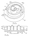
- the outer end portion of spiral element 222 has a height h 2 .
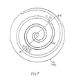
- the inner end surface of end plate 221 is formed with a stepped portion S at an arbitrary involute angle a of spiral element 222, on the inner side of spiral element 222 (this point is shown by 0 1 in Figure 7, which actually depicts the spiral element of fixed scroll member 21-the mirror image of orbiting scroll member 22).
- This stepped portion S has a depth h 3 ; the inner portion of end plate 221, which extends inwardly from this stepped portion S to the center of the spiral, is formed deeper than its outer portion, so that the inner portion of spiral element 222 has height of h 2 +h 3 .
- stepped portion S is concavely semicircular with a radius R 1 ; this radius R 1 is given by where r o is the orbital radius of the orbiting scroll 22 and t is the wall thickness of the spiral element.
- This arcuate end surface of stepped portion S provides clearance for mating spiral element 212, which faces stepped portion S, during orbital motion of scroll member 22.
- spiral element 222 is formed with a transition portion T at position a-n angularly offset from the point 0 1 by n radians, where the spiral height is increased by h ⁇ .
- the end surface of transition portion T is convexly semicircular with a radius of r 2 .
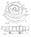
- the configuration of fixed scroll 21, which mates with orbiting scroll 22, is essentially the mirror image of the configuration of orbiting scroll 22.
- a stepped portion S having a depth of h 3 is formed on the end surface of circular end plate 211 at a position of point O 1 shown in Figure 7, and spiral element 212 is provided with a transition portion T at a position a-n angularly offset from point 0, by n radians.
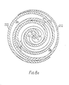
- FIG. 8a shows that the outer terminal end of each spiral element is in contact with the other spiral element, i.e., suction just has been completed, and a symmetrical pair of fluid pockets 3a and 3b just have been formed.
- stepped portion S is located 1 ⁇ .5 ⁇ radians from the outer terminal end of the spiral element.
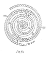
- Figure 8c shows the configuration at a further 90° rotation of the drive shaft.
- contact between the transition portions T and the stepped portions S has been dissolved, so that the pair of fluid pockets are connected to one another through transition portion T.
- the pair of fluid pockets are symmetrically formed by the scrolls and have the same fluid pressure therein, so that a compression loss does not result.
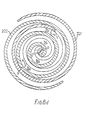
- Figure 8d shows the configuration at a further 90° rotation of the drive shaft.
- Figure 3 illustrates the compression cycle of the above described compressor of the invention.
- the compression cycle of this compressor is shown by points h, h', I', m', n', o and p.
- the conventional compression cycle for a compressor having spirals of uniform height points h, I, m, n, o and p.
- the ratio of fluid pocket volume reduction to change of crank angle in this invention is smaller. Therefore, the fluid in the pocket is more slowly compressed and the internal compression ratio of the compressor is lower, so that the power required for compression is lower.
- the pressure differential between the adjacent fluid pockets is reduced, because the fluid in the pockets is more slowly compressed. Therefore, the fluid leakage from the higher pressure space to the lower pressure space is reduced, thereby improving the volumetric efficiency of the compressor.
- FIG. 9 another embodiment is shown.
- This embodiment is directed to a modification of the scroll which is provided with a plurality of stepped portions and transition portions.
- end plates 211 and 221 each are provided with two stepped portions S 1 and S 2 , each of which is arcuate.
- spiral elements 212, 222 each are provided with two transition portions T 1 and T 2 each end surface of which is arcuate.
- the volume reduction ratio of the fluid pockets is even smaller.
- Circular end plate 211 of fixed scroll 21 is formed with a flat surface and spiral element 212 is provided with a transition portion for changing the spiral height.
- Spiral element 212 has a higher portion from the transition portion to the internal spiral end.
- Circular end plate 221 of orbiting scroll 22 has a stepped portion, which also changes the height of the spiral element.
Landscapes
- Engineering & Computer Science (AREA)
- Mechanical Engineering (AREA)
- General Engineering & Computer Science (AREA)
- Rotary Pumps (AREA)
Claims (7)
Applications Claiming Priority (2)
| Application Number | Priority Date | Filing Date | Title |
|---|---|---|---|
| JP162210/81 | 1981-10-12 | ||
| JP56162210A JPS6037320B2 (ja) | 1981-10-12 | 1981-10-12 | スクロ−ル型圧縮機 |
Publications (2)
| Publication Number | Publication Date |
|---|---|
| EP0077214A1 EP0077214A1 (fr) | 1983-04-20 |
| EP0077214B1 true EP0077214B1 (fr) | 1986-02-19 |
Family
ID=15750054
Family Applications (1)
| Application Number | Title | Priority Date | Filing Date |
|---|---|---|---|
| EP82305428A Expired EP0077214B1 (fr) | 1981-10-12 | 1982-10-12 | Compresseur à volutes imbriquées avec rendement élevé |
Country Status (5)
| Country | Link |
|---|---|
| US (1) | US4457674A (fr) |
| EP (1) | EP0077214B1 (fr) |
| JP (1) | JPS6037320B2 (fr) |
| AU (1) | AU550496B2 (fr) |
| DE (1) | DE3269211D1 (fr) |
Families Citing this family (49)
| Publication number | Priority date | Publication date | Assignee | Title |
|---|---|---|---|---|
| JPS5968583A (ja) * | 1982-10-09 | 1984-04-18 | Sanden Corp | スクロ−ル型流体装置 |
| JPS5952193U (ja) * | 1982-09-30 | 1984-04-05 | サンデン株式会社 | スクロ−ル型圧縮機 |
| JPS59142483U (ja) * | 1983-03-15 | 1984-09-22 | サンデン株式会社 | スクロ−ル型圧縮機の回転阻止機構 |
| AU567905B2 (en) * | 1983-07-25 | 1987-12-10 | Copeland Corporation | Scroll pump |
| KR890000628B1 (ko) * | 1984-05-29 | 1989-03-22 | 미쓰비시전기 주식회사 | 스크롤 유체기계 |
| US4613291A (en) * | 1985-08-01 | 1986-09-23 | Sundstrand Corporation | Inlet construction for a scroll compressor |
| JPS6254734U (fr) * | 1985-09-24 | 1987-04-04 | ||
| US5219281A (en) * | 1986-08-22 | 1993-06-15 | Copeland Corporation | Fluid compressor with liquid separating baffle overlying the inlet port |
| US4767293A (en) * | 1986-08-22 | 1988-08-30 | Copeland Corporation | Scroll-type machine with axially compliant mounting |
| CH673874A5 (fr) * | 1987-03-24 | 1990-04-12 | Bbc Brown Boveri & Cie | |
| JPH0630486U (ja) * | 1992-09-21 | 1994-04-22 | サンデン株式会社 | スクロール型圧縮機 |
| US5388973A (en) * | 1994-06-06 | 1995-02-14 | Tecumseh Products Company | Variable scroll tip hardness |
| JP3053551B2 (ja) * | 1995-08-03 | 2000-06-19 | サンデン株式会社 | ボールカップリング |
| EP0924429B1 (fr) * | 1997-12-18 | 2003-08-13 | Mitsubishi Heavy Industries, Ltd. | Compresseur à spirales |
| JP3115553B2 (ja) * | 1998-01-27 | 2000-12-11 | サンデン株式会社 | スクロール型流体機械における可動スクロールの自転阻止機構 |
| US6511308B2 (en) | 1998-09-28 | 2003-01-28 | Air Squared, Inc. | Scroll vacuum pump with improved performance |
| US6439864B1 (en) | 1999-01-11 | 2002-08-27 | Air Squared, Inc. | Two stage scroll vacuum pump with improved pressure ratio and performance |
| US6050792A (en) * | 1999-01-11 | 2000-04-18 | Air-Squared, Inc. | Multi-stage scroll compressor |
| JP2001132664A (ja) | 1999-11-04 | 2001-05-18 | Sanden Corp | スクロール型圧縮機 |
| JP2001221177A (ja) | 2000-02-10 | 2001-08-17 | Sanden Corp | スクロール型流体機械 |
| US6746224B2 (en) * | 2000-06-22 | 2004-06-08 | Mitsubishi Heavy Industries, Ltd. | Scroll compressor |
| US6494695B1 (en) * | 2000-09-19 | 2002-12-17 | Scroll Technologies | Orbiting scroll center of mass optimization |
| JP2002213372A (ja) * | 2001-01-16 | 2002-07-31 | Mitsubishi Heavy Ind Ltd | スクロール型圧縮機 |
| JP4709439B2 (ja) | 2001-07-24 | 2011-06-22 | 三菱重工業株式会社 | スクロール型圧縮機 |
| US6764288B1 (en) * | 2003-11-06 | 2004-07-20 | Varian, Inc. | Two stage scroll vacuum pump |
| KR100695822B1 (ko) * | 2004-12-23 | 2007-03-20 | 엘지전자 주식회사 | 스크롤 압축기의 계단형 용량 가변장치 |
| US10683865B2 (en) | 2006-02-14 | 2020-06-16 | Air Squared, Inc. | Scroll type device incorporating spinning or co-rotating scrolls |
| JP4813938B2 (ja) * | 2006-03-20 | 2011-11-09 | 三菱重工業株式会社 | スクロール圧縮機 |
| JP4969222B2 (ja) * | 2006-11-29 | 2012-07-04 | 三菱重工業株式会社 | スクロール圧縮機 |
| FR2927672B1 (fr) * | 2008-02-19 | 2012-04-13 | Danfoss Commercial Compressors | Compresseur frigorifique a spirales |
| JP5386219B2 (ja) * | 2009-04-27 | 2014-01-15 | 三菱重工業株式会社 | スクロール圧縮機 |
| GB0912162D0 (en) * | 2009-07-14 | 2009-08-26 | Edwards Ltd | Scroll compressor |
| US11047389B2 (en) | 2010-04-16 | 2021-06-29 | Air Squared, Inc. | Multi-stage scroll vacuum pumps and related scroll devices |
| US20130232975A1 (en) | 2011-08-09 | 2013-09-12 | Robert W. Saffer | Compact energy cycle construction utilizing some combination of a scroll type expander, pump, and compressor for operating according to a rankine, an organic rankine, heat pump, or combined organic rankine and heat pump cycle |
| JP6599099B2 (ja) * | 2014-12-15 | 2019-10-30 | 三菱重工サーマルシステムズ株式会社 | スクロール流体機械 |
| JP6529787B2 (ja) * | 2015-03-05 | 2019-06-12 | 三菱重工サーマルシステムズ株式会社 | スクロール流体機械 |
| JP6685649B2 (ja) * | 2015-03-17 | 2020-04-22 | 三菱重工サーマルシステムズ株式会社 | スクロール圧縮機 |
| US10508543B2 (en) | 2015-05-07 | 2019-12-17 | Air Squared, Inc. | Scroll device having a pressure plate |
| US10865793B2 (en) | 2016-12-06 | 2020-12-15 | Air Squared, Inc. | Scroll type device having liquid cooling through idler shafts |
| JP7102164B2 (ja) * | 2018-02-21 | 2022-07-19 | 三菱重工サーマルシステムズ株式会社 | スクロール流体機械 |
| JP7039320B2 (ja) * | 2018-02-21 | 2022-03-22 | 三菱重工サーマルシステムズ株式会社 | スクロール流体機械 |
| JP7134641B2 (ja) * | 2018-02-21 | 2022-09-12 | 三菱重工サーマルシステムズ株式会社 | スクロール流体機械 |
| EP3788262B1 (fr) | 2018-05-04 | 2024-11-20 | Air Squared, Inc. | Refroidissement par liquide de compresseur, de détendeur ou de pompe à vide à volute fixe et orbitale |
| US11067080B2 (en) | 2018-07-17 | 2021-07-20 | Air Squared, Inc. | Low cost scroll compressor or vacuum pump |
| US20200025199A1 (en) | 2018-07-17 | 2020-01-23 | Air Squared, Inc. | Dual drive co-rotating spinning scroll compressor or expander |
| US11530703B2 (en) | 2018-07-18 | 2022-12-20 | Air Squared, Inc. | Orbiting scroll device lubrication |
| US11473572B2 (en) | 2019-06-25 | 2022-10-18 | Air Squared, Inc. | Aftercooler for cooling compressed working fluid |
| US11898557B2 (en) | 2020-11-30 | 2024-02-13 | Air Squared, Inc. | Liquid cooling of a scroll type compressor with liquid supply through the crankshaft |
| US11885328B2 (en) | 2021-07-19 | 2024-01-30 | Air Squared, Inc. | Scroll device with an integrated cooling loop |
Family Cites Families (3)
| Publication number | Priority date | Publication date | Assignee | Title |
|---|---|---|---|---|
| US2590435A (en) * | 1950-04-29 | 1952-03-25 | Robbins & Myers | Flat rotary pump |
| US3874827A (en) * | 1973-10-23 | 1975-04-01 | Niels O Young | Positive displacement scroll apparatus with axially radially compliant scroll member |
| US4141677A (en) * | 1977-08-15 | 1979-02-27 | Ingersoll-Rand Company | Scroll-type two stage positive fluid-displacement apparatus with intercooler |
-
1981
- 1981-10-12 JP JP56162210A patent/JPS6037320B2/ja not_active Expired
-
1982
- 1982-10-12 DE DE8282305428T patent/DE3269211D1/de not_active Expired
- 1982-10-12 US US06/433,897 patent/US4457674A/en not_active Expired - Lifetime
- 1982-10-12 EP EP82305428A patent/EP0077214B1/fr not_active Expired
- 1982-10-12 AU AU89272/82A patent/AU550496B2/en not_active Expired
Also Published As
| Publication number | Publication date |
|---|---|
| AU550496B2 (en) | 1986-03-20 |
| DE3269211D1 (en) | 1986-03-27 |
| JPS5862395A (ja) | 1983-04-13 |
| AU8927282A (en) | 1983-04-21 |
| US4457674A (en) | 1984-07-03 |
| JPS6037320B2 (ja) | 1985-08-26 |
| EP0077214A1 (fr) | 1983-04-20 |
Similar Documents
| Publication | Publication Date | Title |
|---|---|---|
| US4457674A (en) | High efficiency scroll type compressor with wrap portions having different axial heights | |
| US4477238A (en) | Scroll type compressor with wrap portions of different axial heights | |
| EP0105684B1 (fr) | Compresseur de réfrigérant à volutes avec mécanisme de volutes | |
| US4303379A (en) | Scroll-type compressor with reduced housing radius | |
| US4490099A (en) | Scroll type fluid displacement apparatus with thickened center wrap portions | |
| US4304535A (en) | Scroll-type compressor units with minimum housing and scroll plate radii | |
| US4460321A (en) | Axial clearance adjustment mechanism for scroll type fluid displacement apparatus | |
| EP0078148A1 (fr) | Mécanisme d'entraînement à précontrainte pour membre de déplacement de fluide à mouvement orbital | |
| EP0227249A1 (fr) | Mécanisme d'étanchéité axiale pour appareil à déplacement de fluide du type à volute | |
| US4627799A (en) | Axial sealing mechanism for a scroll type fluid displacement apparatus | |
| US4594061A (en) | Scroll type compressor having reinforced spiral elements | |
| US4548555A (en) | Scroll type fluid displacement apparatus with nonuniform scroll height | |
| EP0099740B1 (fr) | Machine à déplacement de fluide à volutes imbriquées et procédé d'assemblage | |
| EP0118900A1 (fr) | Dispositif de lubrification pour machine à déplacement de fluide à volutes imbriquées | |
| EP0069531B1 (fr) | Compresseur à volutes ayant un mécanisme de refoulement corrigé | |
| EP1132573B1 (fr) | Machine à spirales pour fluides | |
| US5779461A (en) | Scroll type fluid displacement apparatus having a control system of line contacts between spiral elements | |
| US4477239A (en) | Scroll type fluid displacement apparatus with offset wraps for reduced housing diameter | |
| EP0049495B1 (fr) | Appareil à déplacement de fluide à volutes imbriquées | |
| EP0419204B1 (fr) | Appareil avec un piston tournant pour déplacer un fluide et ayant un dispositif empêchant la rotation | |
| EP0429146B1 (fr) | Partie à spirale pour machine pour fluides à déplacement positif à spirales | |
| US4548556A (en) | Interfitting mechanism of spiral elements for scroll-type fluid displacement apparatus | |
| EP0065261B1 (fr) | Joint d'étanchéité axial pour une machine à déplacement à volutes imbriquées | |
| US5738504A (en) | Rotation preventing device for orbiting member of fluid displacement apparatus | |
| EP0012614A1 (fr) | Améliorations à des compresseurs à fluide du type à volutes imbriquées |
Legal Events
| Date | Code | Title | Description |
|---|---|---|---|
| PUAI | Public reference made under article 153(3) epc to a published international application that has entered the european phase |
Free format text: ORIGINAL CODE: 0009012 |
|
| AK | Designated contracting states |
Designated state(s): DE FR GB IT SE |
|
| 17P | Request for examination filed |
Effective date: 19831014 |
|
| ITF | It: translation for a ep patent filed | ||
| GRAA | (expected) grant |
Free format text: ORIGINAL CODE: 0009210 |
|
| AK | Designated contracting states |
Designated state(s): DE FR GB IT SE |
|
| REF | Corresponds to: |
Ref document number: 3269211 Country of ref document: DE Date of ref document: 19860327 |
|
| ET | Fr: translation filed | ||
| PLBE | No opposition filed within time limit |
Free format text: ORIGINAL CODE: 0009261 |
|
| STAA | Information on the status of an ep patent application or granted ep patent |
Free format text: STATUS: NO OPPOSITION FILED WITHIN TIME LIMIT |
|
| 26N | No opposition filed | ||
| ITTA | It: last paid annual fee | ||
| EAL | Se: european patent in force in sweden |
Ref document number: 82305428.3 |
|
| PGFP | Annual fee paid to national office [announced via postgrant information from national office to epo] |
Ref country code: SE Payment date: 20011005 Year of fee payment: 20 |
|
| PGFP | Annual fee paid to national office [announced via postgrant information from national office to epo] |
Ref country code: GB Payment date: 20011010 Year of fee payment: 20 Ref country code: FR Payment date: 20011010 Year of fee payment: 20 |
|
| PGFP | Annual fee paid to national office [announced via postgrant information from national office to epo] |
Ref country code: DE Payment date: 20011029 Year of fee payment: 20 |
|
| REG | Reference to a national code |
Ref country code: GB Ref legal event code: IF02 |
|
| PG25 | Lapsed in a contracting state [announced via postgrant information from national office to epo] |
Ref country code: GB Free format text: LAPSE BECAUSE OF EXPIRATION OF PROTECTION Effective date: 20021011 |
|
| REG | Reference to a national code |
Ref country code: GB Ref legal event code: PE20 Effective date: 20021011 |
|
| EUG | Se: european patent has lapsed |
Ref document number: 82305428.3 |