EP0429146B1 - Partie à spirale pour machine pour fluides à déplacement positif à spirales - Google Patents
Partie à spirale pour machine pour fluides à déplacement positif à spirales Download PDFInfo
- Publication number
- EP0429146B1 EP0429146B1 EP90203257A EP90203257A EP0429146B1 EP 0429146 B1 EP0429146 B1 EP 0429146B1 EP 90203257 A EP90203257 A EP 90203257A EP 90203257 A EP90203257 A EP 90203257A EP 0429146 B1 EP0429146 B1 EP 0429146B1
- Authority
- EP
- European Patent Office
- Prior art keywords
- scroll
- spiral element
- end plate
- housing
- spiral
- Prior art date
- Legal status (The legal status is an assumption and is not a legal conclusion. Google has not performed a legal analysis and makes no representation as to the accuracy of the status listed.)
- Expired - Lifetime
Links
- 239000012530 fluid Substances 0.000 title claims description 26
- 238000006073 displacement reaction Methods 0.000 title claims description 10
- 230000002093 peripheral effect Effects 0.000 claims description 5
- 238000007789 sealing Methods 0.000 claims description 2
- 230000000694 effects Effects 0.000 claims 1
- 230000006835 compression Effects 0.000 description 4
- 238000007906 compression Methods 0.000 description 4
- 238000005266 casting Methods 0.000 description 3
- 230000007423 decrease Effects 0.000 description 1
- 238000007730 finishing process Methods 0.000 description 1
- 239000000463 material Substances 0.000 description 1
- 238000005192 partition Methods 0.000 description 1
Images

Classifications
-
- F—MECHANICAL ENGINEERING; LIGHTING; HEATING; WEAPONS; BLASTING
- F04—POSITIVE - DISPLACEMENT MACHINES FOR LIQUIDS; PUMPS FOR LIQUIDS OR ELASTIC FLUIDS
- F04C—ROTARY-PISTON, OR OSCILLATING-PISTON, POSITIVE-DISPLACEMENT MACHINES FOR LIQUIDS; ROTARY-PISTON, OR OSCILLATING-PISTON, POSITIVE-DISPLACEMENT PUMPS
- F04C18/00—Rotary-piston pumps specially adapted for elastic fluids
- F04C18/02—Rotary-piston pumps specially adapted for elastic fluids of arcuate-engagement type, i.e. with circular translatory movement of co-operating members, each member having the same number of teeth or tooth-equivalents
-
- F—MECHANICAL ENGINEERING; LIGHTING; HEATING; WEAPONS; BLASTING
- F01—MACHINES OR ENGINES IN GENERAL; ENGINE PLANTS IN GENERAL; STEAM ENGINES
- F01C—ROTARY-PISTON OR OSCILLATING-PISTON MACHINES OR ENGINES
- F01C1/00—Rotary-piston machines or engines
- F01C1/02—Rotary-piston machines or engines of arcuate-engagement type, i.e. with circular translatory movement of co-operating members, each member having the same number of teeth or tooth-equivalents
- F01C1/0207—Rotary-piston machines or engines of arcuate-engagement type, i.e. with circular translatory movement of co-operating members, each member having the same number of teeth or tooth-equivalents both members having co-operating elements in spiral form
- F01C1/0246—Details concerning the involute wraps or their base, e.g. geometry
-
- Y—GENERAL TAGGING OF NEW TECHNOLOGICAL DEVELOPMENTS; GENERAL TAGGING OF CROSS-SECTIONAL TECHNOLOGIES SPANNING OVER SEVERAL SECTIONS OF THE IPC; TECHNICAL SUBJECTS COVERED BY FORMER USPC CROSS-REFERENCE ART COLLECTIONS [XRACs] AND DIGESTS
- Y10—TECHNICAL SUBJECTS COVERED BY FORMER USPC
- Y10T—TECHNICAL SUBJECTS COVERED BY FORMER US CLASSIFICATION
- Y10T29/00—Metal working
- Y10T29/49—Method of mechanical manufacture
- Y10T29/49229—Prime mover or fluid pump making
- Y10T29/49236—Fluid pump or compressor making
- Y10T29/4924—Scroll or peristaltic type
Definitions
- the present invention relates to scroll type fluid displacement apparatus, and more particularly, to the outer configuration of a scroll member for scroll type fluid displacement apparatus.
- Scroll type fluid displacement apparatus is well known in the prior art.
- US-A-4494914 discloses a fluid displacement apparatus which includes a pair of interfitting scroll members. Each scroll member has a circular end plate and a spiral element extending from one end surface of the end plate. These scroll members are maintained angularly and radially offset so that they interfit and make a plurality of line contracts between their spiral curved surfaces and, as a result, the volume of the fluid pocket changes. Since the volume of the fluid pockets increases or decreases according to the direction of the orbital motion, such scroll type displacement apparatus is applicable to compress, expand or pump fluids.
- the inner and outer wall surfaces of the spiral elements and the axial end surfaces of the end plates may be provided with a finishing process over their entire surfaces, by turning in conventional manner.
- this takes a long time, and since the entire surfaces of the scrolls are finished by turning, much material of the scrolls will be wasted. See also JP-A-59-37289
- a primary object of this invention is to provide scrolls for a scroll type fluid displacement apparatus which can be manufactured in a shorter time, and another object of this invention to provide scrolls which can be manufactured at low cost.
- apparatus of the above mentioned type is characterized in that at least one of the circular end plates of the scroll members is provided with either an unfinished steplike rebate portion at an outer peripheral edge portion thereof, the rebate portion extending from the outer end of the corresponding spiral element, and having an inner wall l following the path of an extension of the involute curve l' defining the inner wall surface of the spiral element, or with an unfinished portion at the same position.
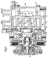
- a scroll type fluid displacement apparatus which consists of a scroll type compressor.
- the compressor includes a compressor housing 10 having a front end plate 11 and a cup-shaped casing 12 which is attached to an end surface of the front end plate 11.
- An opening 111 is formed in the centre of the front end plate 11 for a drive shaft 13.
- the casing 12 is fixed to the inside surface of the front end plate 11 by fastening devices, for example bolts and nuts (not shown), so that the open end of the casing 12 is covered by the front end plate 11.
- the front end plate 11 has an annular sleeve 15 projecting from its front end surface, the sleeve 15 surrounding the drive shaft 13 to define a shaft seal cavity.
- a shaft seal assembly 16 is assembled on the drive shaft 13 within the shaft seal cavity.
- the drive shaft 13 is formed with a disk-shaped rotor 131, at its inner end, rotatably supported by the front end plate 11 through a bearing 14 located within the opening 111.
- the drive shaft 13 is also rotatably supported by the sleeve 15 through a bearing 17.
- the outer end of the drive shaft 13 which extends from the sleeve 15 is connected to a rotation transmitting device, for example, an electromagnetic clutch which may be disposed on the outer peripheral surface of the sleeve 15 for transmitting rotary movement to the drive shaft 13.
- a rotation transmitting device for example, an electromagnetic clutch which may be disposed on the outer peripheral surface of the sleeve 15 for transmitting rotary movement to the drive shaft 13.
- the drive shaft 13 is driven by an external power source, for example, the engine of a vehicle, through the rotating transmitting device.
- a number of elements are located within the inner chamber of cup-shaped casing 12, including a fixed scroll 18, an orbiting scroll 19, a driving mechanism for the orbiting scroll 19 and a rotation preventing/thrust bearing device 20 for the orbiting scroll 19, formed between the inner wall of the casing 12 and the rear end surface of the front end plate 11.
- the fixed scroll 18 includes a circular end plate 181, a spiral element 182 affixed to and extending from one end surface of the circular end plate 181 and a plurality of internally threaded bosses 183 axially projecting from the outer end surface of the end plate 181.
- the axial end surface of each boss 183 is seated on the inner surface of an end plate 121 of the casing 12 and fixed therewithin by bolts 21.
- the circular end plate 181 partitions the inner chamber of the casing 12 into two chambers: a discharge chamber 22 and a suction chamber 23.
- a seal ring 24 is located between the outer peripheral surface of the end plate 181 and the inner wall of the casing 12 to seal off and define the two chambers.
- a discharge port 184 which interconnects the centre portions of the scrolls with the discharge chamber 22, is formed through the end plate 181.
- the orbiting scroll 19 also includes a circular end plate 191 and a spiral element 192 affixed to and extending from one side surface of the end plate 191.
- the spiral element 192 of the orbiting scroll 19 and the spiral element 182 of the fixed scroll interfit at an angular offset of 180° and a predetermined radial offset. At least a pair of sealed off fluid pockets are thereby defined between the spiral elements 182,192.
- Each scroll which comprises a spiral element and circular end plate integrally formed with one another, is initially formed by casting, and this initially formed scroll is finished by turning to obtain an accurate surface to ensure sealing of the interfitting scrolls.
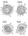
- FIG. 2 shows the relationship of fluid in the fluid pocket to crank angle, and shows that one compression cycle is completed in this case at a crank angle of 360°.
- Two spiral elements 182, 192 are angularly offset and interfit with one another.
- the orbiting spiral element 192 and fixed spiral element 182 make four line contacts A-D.
- a pair of fluid pockets A1, A2 are defined between line contacts D-C and line contacts A-B, as shown by the dotted regions.
- the fluid pockets A1, A2 are defined not only by the wall of spiral elements 182, 192 but also by the end plates.
- a fixed scroll 18 in accordance with a further embodiment of this invention is shown.
- the circular end plate 181 of the fixed scroll 18 is provided with a stepped rebate 185 at its outer peripheral edge portion, extending over 180° from the outer terminal end of the spiral element 181.
- the rebate portion 185 of the end plate 181 is formed on the outerside of an imaginary line l which is an extension of the involute curve defines the inner wall surface of the spiral element 182.
- the inner wall surface line l' of the rebate portion 185 may be shifted inwardly of the involute curve l whilst still securing effective compression.
- the rebate portion 185 is initially formed by casting so that its height from the other end surface of the end plate 181 is less than the height of the other portion of the end plate 181 which is subsequently finished by turning.
- FIG. 5 an enlarged view illustrating the outer end portion of the spiral element 182 is shown.
- An arc-shaped shaped slant surface 186 is formed between the spiral element 182 and the end plate 181 to reinforce the base of the spiral element 182.
- the arc-shaped slant surface 186 is defined with an axial height h from the surface of the rebate portion 185. The axial height h can be small until the position in which the spiral element 182 may not be broken down.
- the arc-shaped slant surface 186 is formed by casting, and is not finished by turning.
Landscapes
- Engineering & Computer Science (AREA)
- Mechanical Engineering (AREA)
- General Engineering & Computer Science (AREA)
- Physics & Mathematics (AREA)
- Geometry (AREA)
- Rotary Pumps (AREA)
Claims (2)
- Appareil à déplacement de fluide de type à volutes comprenant un boîtier (12), une paire d'éléments de volutes (18), (19), l'un (18) des éléments de volutes étant monté de façon fixe par rapport au boîtier et comportant une plaque d'extrémité circulaire (181) sur laquelle fait saillie un premier élément de spirale (182) pénétrant à l'intérieur du boîtier, et l'autre élément de volute (19) étant monté de manière à pouvoir effectuer un mouvement orbital sans rotation à l'intérieur du boîtier, cet élément de volute mobile comportant une plaque d'extrémité (191) sur laquelle fait saillie un second élément de spirale (182), le premier élément de spirale et le second élément de spirale s'emboîtant avec un décalage angulaire et radial de manière à former un certain nombre de lignes de contact (A à D) pour définir au moins une paire de poches à fluide étanches (A₁, A₂), et des moyens d'entraînement (13) reliés en fonctionnement à l'autre élément de volute (19) pour produire son mouvement orbital et celui des lignes de contact, ce qui permet ainsi aux poches à fluide (A₁, A₂) de se déplacer vers l'intérieur et de changer de volume, chaque élément de volute étant réalisé initialement sous une forme grossière correspondant approximativement à sa forme usinée finale, puis ensuite soumis à un usinage de finition pour obtenir une surface précise assurant l'étanchéité des poches à fluide, caractérisé en ce que
l'une au moins des plaques d'extrémité circulaires (181, 191) des éléments de volutes est munie d'une partie de feuillure en forme de gradin sans usinage de finition (185) à l'endroit d'une partie de bord périphérique extérieur de celle-ci, cette partie de feuillure (185) partant de l'extrémité extérieure de l'élément de spirale correspondant (182, 192) et comportant une paroi intérieure l' suivant le chemin d'un prolongement de la courbe de développante l définissant la surface de paroi intérieure de l'élément de spirale (182, 192). - Appareil selon la revendication 1, caractérisé en ce qu'une partie en forme d'arc (186) est formée pour constituer une partie de base de l'élément de spirale (1982) au voisinage de la partie de feuillure (185).
Applications Claiming Priority (4)
| Application Number | Priority Date | Filing Date | Title |
|---|---|---|---|
| JP61098797A JPS62255501A (ja) | 1986-04-28 | 1986-04-28 | スクロ−ル型流体吸排装置用スクロ−ル部材 |
| JP98797/86 | 1986-04-28 | ||
| JP98798/86 | 1986-04-28 | ||
| JP9879886A JPS62255502A (ja) | 1986-04-28 | 1986-04-28 | スクロ−ル型流体吸排装置用スクロ−ル部材 |
Related Parent Applications (1)
| Application Number | Title | Priority Date | Filing Date |
|---|---|---|---|
| EP87303700.6 Division | 1987-04-27 |
Publications (2)
| Publication Number | Publication Date |
|---|---|
| EP0429146A1 EP0429146A1 (fr) | 1991-05-29 |
| EP0429146B1 true EP0429146B1 (fr) | 1993-12-08 |
Family
ID=26439909
Family Applications (2)
| Application Number | Title | Priority Date | Filing Date |
|---|---|---|---|
| EP90203257A Expired - Lifetime EP0429146B1 (fr) | 1986-04-28 | 1987-04-27 | Partie à spirale pour machine pour fluides à déplacement positif à spirales |
| EP87303700A Expired - Lifetime EP0244183B1 (fr) | 1986-04-28 | 1987-04-27 | Elément de volute pour machine déplaçant des fluides à volutes imbriquées |
Family Applications After (1)
| Application Number | Title | Priority Date | Filing Date |
|---|---|---|---|
| EP87303700A Expired - Lifetime EP0244183B1 (fr) | 1986-04-28 | 1987-04-27 | Elément de volute pour machine déplaçant des fluides à volutes imbriquées |
Country Status (6)
| Country | Link |
|---|---|
| US (1) | US4824345A (fr) |
| EP (2) | EP0429146B1 (fr) |
| KR (1) | KR950011371B1 (fr) |
| AU (2) | AU593098B2 (fr) |
| CA (1) | CA1303418C (fr) |
| DE (2) | DE3788434T2 (fr) |
Families Citing this family (15)
| Publication number | Priority date | Publication date | Assignee | Title |
|---|---|---|---|---|
| AU632332B2 (en) * | 1989-06-20 | 1992-12-24 | Sanden Corporation | Scroll type fluid displacement apparatus |
| US5094205A (en) * | 1989-10-30 | 1992-03-10 | Billheimer James C | Scroll-type engine |
| JP3029228B2 (ja) * | 1993-08-17 | 2000-04-04 | トーヨーエイテック株式会社 | スクロール状工作物の加工方法及び装置 |
| JP3016536B2 (ja) * | 1994-03-15 | 2000-03-06 | 株式会社デンソー | スクロール型圧縮機 |
| EP0753667B1 (fr) * | 1995-07-10 | 2003-03-12 | Kabushiki Kaisha Toyota Jidoshokki | Compresseur à spirales et procédé de production d'un élément à spirale |
| US5615480A (en) * | 1995-08-16 | 1997-04-01 | Amcast Industrial Corporation | Methods for making scroll compressor element |
| CN1082146C (zh) * | 1995-08-31 | 2002-04-03 | 三菱重工业株式会社 | 涡旋型流体机械 |
| JP3771666B2 (ja) * | 1997-04-10 | 2006-04-26 | サンデン株式会社 | スクロール型流体機械用スクロール部材 |
| US6135736A (en) * | 1997-10-23 | 2000-10-24 | Copeland Corporation | Scroll machine with non-machined anti-thrust surface |
| US6410726B1 (en) | 2000-01-12 | 2002-06-25 | Tularik Inc. | Arylsulfonic acid salts of pyrimidine-based antiviral |
| JP2001221177A (ja) | 2000-02-10 | 2001-08-17 | Sanden Corp | スクロール型流体機械 |
| JP2005023817A (ja) * | 2003-07-01 | 2005-01-27 | Matsushita Electric Ind Co Ltd | スクロール圧縮機およびスクロールラップの加工方法 |
| US7841845B2 (en) * | 2005-05-16 | 2010-11-30 | Emerson Climate Technologies, Inc. | Open drive scroll machine |
| US7958862B2 (en) * | 2007-12-07 | 2011-06-14 | Secco2 Engines, Inc. | Rotary positive displacement combustor engine |
| US8006496B2 (en) | 2008-09-08 | 2011-08-30 | Secco2 Engines, Inc. | Closed loop scroll expander engine |
Family Cites Families (12)
| Publication number | Priority date | Publication date | Assignee | Title |
|---|---|---|---|---|
| JPS5537537A (en) * | 1978-09-09 | 1980-03-15 | Sanden Corp | Volume type liquid compressor |
| JPS5551987A (en) * | 1978-10-12 | 1980-04-16 | Sanden Corp | Positive displacement fluid compressor |
| JPS586075B2 (ja) * | 1980-10-03 | 1983-02-02 | サンデン株式会社 | スクロ−ル型圧縮機 |
| US4403494A (en) * | 1981-03-02 | 1983-09-13 | Arthur D. Little, Inc. | Method of fabricating scroll members by coining and tools therefor |
| JPS57190726A (en) * | 1981-05-20 | 1982-11-24 | Sanden Corp | Method and apparatus for working scroll member |
| JPS57189702A (en) * | 1981-05-20 | 1982-11-22 | Sanden Corp | Working method and device of scroll member |
| JPS58172404A (ja) * | 1982-04-05 | 1983-10-11 | Hitachi Ltd | スクロ−ル流体機械 |
| US4487248A (en) * | 1982-07-23 | 1984-12-11 | Sanden Corporation | Scroll manufacturing method and tool |
| JPS5937289A (ja) * | 1982-08-27 | 1984-02-29 | Hitachi Ltd | スクロ−ル圧縮機 |
| JPS59142481U (ja) * | 1983-03-15 | 1984-09-22 | サンデン株式会社 | スクロ−ル型流体装置 |
| JPS60222580A (ja) * | 1984-04-20 | 1985-11-07 | Hitachi Ltd | スクロ−ル流体機械 |
| AU592756B2 (en) * | 1984-06-18 | 1990-01-25 | Mitsubishi Jukogyo Kabushiki Kaisha | Scroll type fluid machine and method for forming scroll members used therein |
-
1987
- 1987-04-27 DE DE3788434T patent/DE3788434T2/de not_active Expired - Lifetime
- 1987-04-27 DE DE8787303700T patent/DE3772615D1/de not_active Expired - Lifetime
- 1987-04-27 EP EP90203257A patent/EP0429146B1/fr not_active Expired - Lifetime
- 1987-04-27 EP EP87303700A patent/EP0244183B1/fr not_active Expired - Lifetime
- 1987-04-27 AU AU72101/87A patent/AU593098B2/en not_active Expired
- 1987-04-28 KR KR1019870004094A patent/KR950011371B1/ko not_active Expired - Lifetime
- 1987-04-28 CA CA000535801A patent/CA1303418C/fr not_active Expired - Lifetime
- 1987-04-28 US US07/043,460 patent/US4824345A/en not_active Expired - Lifetime
-
1989
- 1989-12-12 AU AU46133/89A patent/AU615361B2/en not_active Expired
Also Published As
| Publication number | Publication date |
|---|---|
| EP0244183B1 (fr) | 1991-09-04 |
| KR870010318A (ko) | 1987-11-30 |
| DE3788434D1 (de) | 1994-01-20 |
| EP0429146A1 (fr) | 1991-05-29 |
| US4824345A (en) | 1989-04-25 |
| AU7210187A (en) | 1987-10-29 |
| EP0244183A2 (fr) | 1987-11-04 |
| EP0244183A3 (en) | 1988-09-14 |
| CA1303418C (fr) | 1992-06-16 |
| AU615361B2 (en) | 1991-09-26 |
| KR950011371B1 (ko) | 1995-10-02 |
| DE3788434T2 (de) | 1994-06-09 |
| AU593098B2 (en) | 1990-02-01 |
| AU4613389A (en) | 1990-03-29 |
| DE3772615D1 (de) | 1991-10-10 |
Similar Documents
| Publication | Publication Date | Title |
|---|---|---|
| US4477238A (en) | Scroll type compressor with wrap portions of different axial heights | |
| US4303379A (en) | Scroll-type compressor with reduced housing radius | |
| EP0077214B1 (fr) | Compresseur à volutes imbriquées avec rendement élevé | |
| EP0105684B1 (fr) | Compresseur de réfrigérant à volutes avec mécanisme de volutes | |
| EP0429146B1 (fr) | Partie à spirale pour machine pour fluides à déplacement positif à spirales | |
| US4304535A (en) | Scroll-type compressor units with minimum housing and scroll plate radii | |
| EP0010930B1 (fr) | Compresseurs du type spiroidal | |
| EP0106288B1 (fr) | Compresseur à volutes | |
| US4627800A (en) | Scroll type fluid displacement compressor with spiral wrap elements of varying thickness | |
| EP0106287B1 (fr) | Appareil à volutes pour déplacer un fluide | |
| US4627799A (en) | Axial sealing mechanism for a scroll type fluid displacement apparatus | |
| EP0118900B1 (fr) | Dispositif de lubrification pour machine à déplacement de fluide à volutes imbriquées | |
| US4432708A (en) | Scroll type fluid displacement apparatus with pressure communicating passage between pockets | |
| EP0069531B1 (fr) | Compresseur à volutes ayant un mécanisme de refoulement corrigé | |
| US4477239A (en) | Scroll type fluid displacement apparatus with offset wraps for reduced housing diameter | |
| EP0123407B1 (fr) | Dispositif empêchant la rotation pour un appareil volumétrique à piston orbitant | |
| EP0126238B1 (fr) | Compresseur à volutes | |
| EP0065261B1 (fr) | Joint d'étanchéité axial pour une machine à déplacement à volutes imbriquées | |
| EP0189650B1 (fr) | Dispositif d'étanchéité axiale pour compresseur à volutes imbriquées | |
| GB2121480A (en) | Scroll-type rotary compressor | |
| EP0122066A1 (fr) | Appareil à volutes pour le transport d'un fluide ayant un dispositif empêchant le mouvement axial du palier pour le mécanisme de commande | |
| GB2167131A (en) | Scroll-type rotary fluid-machine | |
| CA2091482A1 (fr) | Anneau antigiratoire pour turbomachine |
Legal Events
| Date | Code | Title | Description |
|---|---|---|---|
| PUAI | Public reference made under article 153(3) epc to a published international application that has entered the european phase |
Free format text: ORIGINAL CODE: 0009012 |
|
| AC | Divisional application: reference to earlier application |
Ref document number: 244183 Country of ref document: EP |
|
| AK | Designated contracting states |
Kind code of ref document: A1 Designated state(s): DE FR GB IT SE |
|
| 17P | Request for examination filed |
Effective date: 19911122 |
|
| 17Q | First examination report despatched |
Effective date: 19921005 |
|
| GRAA | (expected) grant |
Free format text: ORIGINAL CODE: 0009210 |
|
| AC | Divisional application: reference to earlier application |
Ref document number: 244183 Country of ref document: EP |
|
| AK | Designated contracting states |
Kind code of ref document: B1 Designated state(s): DE FR GB IT SE |
|
| REF | Corresponds to: |
Ref document number: 3788434 Country of ref document: DE Date of ref document: 19940120 |
|
| ET | Fr: translation filed | ||
| ITF | It: translation for a ep patent filed | ||
| PLBE | No opposition filed within time limit |
Free format text: ORIGINAL CODE: 0009261 |
|
| STAA | Information on the status of an ep patent application or granted ep patent |
Free format text: STATUS: NO OPPOSITION FILED WITHIN TIME LIMIT |
|
| 26N | No opposition filed | ||
| EAL | Se: european patent in force in sweden |
Ref document number: 90203257.2 |
|
| REG | Reference to a national code |
Ref country code: GB Ref legal event code: IF02 |
|
| PGFP | Annual fee paid to national office [announced via postgrant information from national office to epo] |
Ref country code: SE Payment date: 20060406 Year of fee payment: 20 |
|
| PGFP | Annual fee paid to national office [announced via postgrant information from national office to epo] |
Ref country code: FR Payment date: 20060410 Year of fee payment: 20 |
|
| PGFP | Annual fee paid to national office [announced via postgrant information from national office to epo] |
Ref country code: DE Payment date: 20060420 Year of fee payment: 20 |
|
| PGFP | Annual fee paid to national office [announced via postgrant information from national office to epo] |
Ref country code: GB Payment date: 20060426 Year of fee payment: 20 |
|
| PGFP | Annual fee paid to national office [announced via postgrant information from national office to epo] |
Ref country code: IT Payment date: 20060430 Year of fee payment: 20 |
|
| REG | Reference to a national code |
Ref country code: GB Ref legal event code: PE20 |
|
| EUG | Se: european patent has lapsed | ||
| PG25 | Lapsed in a contracting state [announced via postgrant information from national office to epo] |
Ref country code: GB Free format text: LAPSE BECAUSE OF EXPIRATION OF PROTECTION Effective date: 20070426 |