EP0077307A2 - Window frame with one or more upright-sliding shutters - Google Patents
Window frame with one or more upright-sliding shutters Download PDFInfo
- Publication number
- EP0077307A2 EP0077307A2 EP82830244A EP82830244A EP0077307A2 EP 0077307 A2 EP0077307 A2 EP 0077307A2 EP 82830244 A EP82830244 A EP 82830244A EP 82830244 A EP82830244 A EP 82830244A EP 0077307 A2 EP0077307 A2 EP 0077307A2
- Authority
- EP
- European Patent Office
- Prior art keywords
- shutter
- window
- shutters
- window frame
- fact
- Prior art date
- Legal status (The legal status is an assumption and is not a legal conclusion. Google has not performed a legal analysis and makes no representation as to the accuracy of the status listed.)
- Withdrawn
Links
Images


Classifications
-
- E—FIXED CONSTRUCTIONS
- E06—DOORS, WINDOWS, SHUTTERS, OR ROLLER BLINDS IN GENERAL; LADDERS
- E06B—FIXED OR MOVABLE CLOSURES FOR OPENINGS IN BUILDINGS, VEHICLES, FENCES OR LIKE ENCLOSURES IN GENERAL, e.g. DOORS, WINDOWS, BLINDS, GATES
- E06B9/00—Screening or protective devices for wall or similar openings, with or without operating or securing mechanisms; Closures of similar construction
- E06B9/02—Shutters, movable grilles, or other safety closing devices, e.g. against burglary
- E06B9/04—Shutters, movable grilles, or other safety closing devices, e.g. against burglary of wing type, e.g. revolving or sliding
Definitions
- the object of this invention is a special window-frame which can be made in wood, metal (steel or aluminium and its alloys), or in other suitable materials, and which is provided with one or more upright-sliding shutters, each of them having a different function.
- window-frames are components in building constructions intended to complete the openings made in outer walls, with the aim of protecting the inner room from atmospheric agents, without being prejudicial to natural light coming from the outside, or intended to be supplied with darkening means or defending locks.
- the closing can be obtained by means of a fixed panel and of a moving one (sash window) or, on the other hand, by two moving panels sliding along coplanar, or not in the same plane, grooves.
- the window frame wich is the object of the named invention aims at eliminating the above-said disadvantages.
- this invention also solves the problem to produce a window frame with upright-sliding shutters which let the whole light of the window space pass through it, and the closing of which be complete and perfectly airtight, even if the shutters themselves are opaque to light or they consist in thermal insulating blinds or panels.
- the window frame is composed of a big case 1 which is different from the ones manufactured up to now, for its total height (H), if we consider the due tolerances, is twice the height (F) of the window-spece 2, so the shutters 3 (windowpane), 4 (blind), 5 (protection panel), each of them being as much high as the window-space itself and sliding along vertical grooves 6, can occlude the window-space completely or disappear completely into the wall when they are entirely lifted.
- the big case 1 is mounted, as Fig. 2 and 4b show, in such a way that its top part may be included in that part of the outer wall thickness (S) which is not occupied by the thickness (D) of a reinforced-concrete panel 7or by one in another suitable material, the hai g ht (L) of which is like the one of the window-space: this latter also acts as lintel delimiting it on the upper part.
- each of the shutters sliding in the thickness (D) of the case occludes the window-space completely,
- the horizontal crosspieces 9 applied on the case are supplied with a suitable longitudinal weather strip 10 which holds on the surface of the opposed shutter, for instance 3 or 5, securing the complete thermal insulation between the outside and the inner room.
- the upper horizontal crosspieces of the sash constituting the pane 3 and of the shutter frame 5 are supplied with a rabbet tooth 11 which is intended to lean on the opposed crosspiece 9.
- the Fig. 5 shows some latch-devices for shutter-lifting, which can stop each shutter in its closing position or can avoid the sash-falling of it.
- each shutter In the device of Fig. 5a the locking of each shutter is obtained by pins 12a mounted on the upper crosspiece of the frame of each shutter: they penetrate into the holes 13 of the vertical grooves 6 when the shutter is lifted from the bottom, or in the case the little cable 14 breaks, under the . pressure caused by a spring 12b.
- each shutter is executed through a threaded rod 15 which, by means of some driving gears 16, is caused to rotate in a lead nut 17 which is integral with the upper crosspiece of each shutter.
- a horizontal-axed device 18 for the self-cleaning of the outer surface of the pane of glass, acting through a slipping movement and both ends of which are inserted in suitable spots on the vertical inner surface of the case.
- the vertical grooves 6 are also supplied with weather strips 6a to improve the tightness of the shutters.
- the Fig. 3 shows the section of a metal profile in order to realize a three-shutter-window frame.
Landscapes
- Engineering & Computer Science (AREA)
- Structural Engineering (AREA)
- Architecture (AREA)
- Civil Engineering (AREA)
- Wing Frames And Configurations (AREA)
- Operating, Guiding And Securing Of Roll- Type Closing Members (AREA)
Abstract
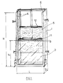
This window frame allows the complete closing or opening of the window-space by means of a single upright-sliding shutter disappearing entirely into the wall, when it is completely lifted. If it contains more shutters, each of them carries on a specific function of its own and by itself, that is the function of a windowpane or a blind or a house-breaking proof closing device. It allows an high degree of thermal insulation of the room both because it is lacking in all those slits through which air filters in common roller shutters, and because the shuter 5 can be high termal insulating. The shutters can be supplied with a locking device which be inaccessible and off sight in order to prevent them from being lifted from the outside, even when they are partly lifted in an opening position. For a better comprehension, see Fig. 1.
Description
- The object of this invention is a special window-frame which can be made in wood, metal (steel or aluminium and its alloys), or in other suitable materials, and which is provided with one or more upright-sliding shutters, each of them having a different function.
- As we know, window-frames are components in building constructions intended to complete the openings made in outer walls, with the aim of protecting the inner room from atmospheric agents, without being prejudicial to natural light coming from the outside, or intended to be supplied with darkening means or defending locks.
- On the whole, they are composed of a wooden or metal big frame i. e. main frame, delimiting the opening of the window-space, usually anchored by means of staffs and laying on the reveal, on the which shutters or moving panels are mounted, The connection between the case and each of the shutters can be obtained by hinges which let the shutters swing on a vertical or a horizontal axis, or by means of slide guides which are horizontal or vertical too.
- In the case we have upright sliding shutters, the closing can be obtained by means of a fixed panel and of a moving one (sash window) or, on the other hand, by two moving panels sliding along coplanar, or not in the same plane, grooves. These last closing systems present several defects:
- a) impossibility to open the window-space completely;
- b) difficulty in obtaining an efficacious tightness along the contact lines between the shutters, especially when they are not in the same plane; c) impossibility to make use of darkening shutters or opaque shutters if we want to avoid the permanent darkening of an half window-space at least;
- d) impossibility to apply authomatic locking devices or shutter-blocking-up ones, which can be inaccessible and off sight; e) difficulty in cleaning the outer surface of the panes of glass and in applying self-cleaning devices;
- f) impossibility to close the rooms assuring an elevated thermoacoustic insulation, more than the one double window panes can grant.
- Besides, all that prevents from producing polyvalent window frames which can be supplied at the same time with panes, shutters, blinds and, if necessary, with mosquitonets.
- The window frame wich is the object of the named invention aims at eliminating the above-said disadvantages.
- Fist of all, it solves the problem of producing a window frame with upright-sliding shutters of a polyvalent kind, that is, which can be used at the same time if necessary, to mount a pane, a blind, a protecting shutter, all of them sliding. ,
- At the same time, this invention also solves the problem to produce a window frame with upright-sliding shutters which let the whole light of the window space pass through it, and the closing of which be complete and perfectly airtight, even if the shutters themselves are opaque to light or they consist in thermal insulating blinds or panels.
- The invention is described as follows according to a favourite execution and referring to the pictures in the plates of drawings enclosed herewith, which explain respectively:
- Fig. 1, an axomometric view of the window frame;
- Fig, 2, one of its vertical sections;
- Fig. 3, The transversal section of a structural steel composing the frame;
- Fig. 4, the schematic representation of the elements of the frame which distinguish the invention;
- Fig. 5, system regulating the vertical movement of the shutters.
- The window frame is composed of a
big case 1 which is different from the ones manufactured up to now, for its total height (H), if we consider the due tolerances, is twice the height (F) of the window-spece 2, so the shutters 3 (windowpane), 4 (blind), 5 (protection panel), each of them being as much high as the window-space itself and sliding alongvertical grooves 6, can occlude the window-space completely or disappear completely into the wall when they are entirely lifted. - To this end, the
big case 1 is mounted, as Fig. 2 and 4b show, in such a way that its top part may be included in that part of the outer wall thickness (S) which is not occupied by the thickness (D) of a reinforced-concrete panel 7or by one in another suitable material, the haight (L) of which is like the one of the window-space: this latter also acts as lintel delimiting it on the upper part. As we can see in Fig. 2 and 4b, each of the shutters sliding in the thickness (D) of the case occludes the window-space completely, - In order to prevent any air infiltration from the outside, along the
dashed line 8 in Fig. 4c, thehorizontal crosspieces 9 applied on the case are supplied with a suitablelongitudinal weather strip 10 which holds on the surface of the opposed shutter, forinstance - Besides, in order to improve the tightness of closing, the upper horizontal crosspieces of the sash constituting the
pane 3 and of theshutter frame 5 are supplied with arabbet tooth 11 which is intended to lean on theopposed crosspiece 9. - The Fig. 5 shows some latch-devices for shutter-lifting, which can stop each shutter in its closing position or can avoid the sash-falling of it.
- In the device of Fig. 5a the locking of each shutter is obtained by
pins 12a mounted on the upper crosspiece of the frame of each shutter: they penetrate into theholes 13 of thevertical grooves 6 when the shutter is lifted from the bottom, or in the case thelittle cable 14 breaks, under the . pressure caused by aspring 12b. - In the device shown in Fig. 5b, the lifting of each shutter is executed through a threaded
rod 15 which, by means of somedriving gears 16, is caused to rotate in alead nut 17 which is integral with the upper crosspiece of each shutter. In Fig. 2, we may also see a horizontal-axed device 18 for the self-cleaning of the outer surface of the pane of glass, acting through a slipping movement and both ends of which are inserted in suitable spots on the vertical inner surface of the case. - The
vertical grooves 6 are also supplied withweather strips 6a to improve the tightness of the shutters. - The Fig. 3 shows the section of a metal profile in order to realize a three-shutter-window frame.
- The characteristics of the invention, which are schematically represented in Fig. 4, are respectively:
- a) height (H) of the case, which is twice the height of the window-space;
- b) way of inserting the window frame into the wall;
- c) seals on the top part of the shutters in their closing position;
- d) a set of panels inserted in the window frame.
Claims (7)
1. Window frame with one or more upright-sliding shutters, characterized by the fact that, all tolerances consi:dered, its height (H) is twice the height (F) of the window-space, or twice the height of each one of the shutters themselves functioning, for instance, as windowpane, blind, protection shutter respectively.
2. Window frame as per claim 1, characterized by the fact that each one of the shutters has got a complete and specific function of its own, only by itself and independently from the other ones: for instance, that one of a windowpane or a blind or a protection shutter, each shutter disappears completely into the wall when it opens the window-space entirely.
3. Window frame as per claim 2, characterized by the fact that each one of the shutters is inserted in the case thickness (D) parallel with the other ones, into a couple of parallel and opposed vertical grooves 6, for the height of each shutter is such as to occlude the window-space completely height way, and because in this way each of them can carry on its own specific function, independently from the other ones and only by itself.
4. Window frame as per previous claims, characterized by the fact that the vertical seals of the panels constituting each shutter are supplied with suitable weather strips 6a which lay within the same vertical grooves of the case they slide along, while the horizontal seals, which are intended to prevent the breaths of air from passing through the dashed line 8, or through the slits between the horizontal upper edge of the frame of each shutter and the horizontal opposed crosspiece 9 of the case, are supplied with suitable horizontal-axed weather strips 10 applied on the two horizontal crosspieces themselves in such a way as to slip on the adjacent surfaces of the windowpane or those of the closing panel or of the horizontal upper crosspiece of the blind frame.
5. Window frame as per claims above, characterized by the fact that it can be supplied with inaccessible or self- locking authomatic closing devices, for instance 12, which are placed in the top part of each shutter:'this part is protected by the crosspiece 9 and covered by the reinforced-concrete panel 7 or by the outer wall in order to prevent any vertical shifting of each shutter from the outside even though partially lifted,
6. Window frame as per previos claims, characterized by the fact that the shutters themselves can be even more than three.
7. Window frame as per previous claims, characterized by the fact that half a height (H) of the frame itself is completely covered by the outer wall, all tolerances considered, in such a way as to be inaccessible, while the other half can be entirely occluded or left open by each of the panels constituting each shutter to close or to open the window-space.
Applications Claiming Priority (2)
| Application Number | Priority Date | Filing Date | Title |
|---|---|---|---|
| IT8102120A IT8102120A0 (en) | 1981-09-30 | 1981-09-30 | AUTOMATIC WINDOW |
| IT212081 | 1981-09-30 |
Publications (2)
| Publication Number | Publication Date |
|---|---|
| EP0077307A2 true EP0077307A2 (en) | 1983-04-20 |
| EP0077307A3 EP0077307A3 (en) | 1983-10-05 |
Family
ID=11102573
Family Applications (1)
| Application Number | Title | Priority Date | Filing Date |
|---|---|---|---|
| EP82830244A Withdrawn EP0077307A3 (en) | 1981-09-30 | 1982-09-29 | Window frame with one or more upright-sliding shutters |
Country Status (2)
| Country | Link |
|---|---|
| EP (1) | EP0077307A3 (en) |
| IT (1) | IT8102120A0 (en) |
Cited By (2)
| Publication number | Priority date | Publication date | Assignee | Title |
|---|---|---|---|---|
| GB2344418B (en) * | 1998-09-01 | 2003-04-02 | David Huw Stephens | Heating and ventilation of dwellings |
| CN106368585A (en) * | 2016-10-20 | 2017-02-01 | 金陵科技学院 | Invisible anti-theft window |
Family Cites Families (6)
| Publication number | Priority date | Publication date | Assignee | Title |
|---|---|---|---|---|
| GB591293A (en) * | 1945-03-26 | 1947-08-13 | Donald Brown | Improvements relating to windows for buildings |
| GB224612A (en) * | 1923-08-18 | 1924-11-18 | Frederick Christian Dreier | Improved means for securing windows in railway carriages and other vehicles, in any desired position |
| DE2039037A1 (en) * | 1970-08-06 | 1972-05-10 | Karl Wurzer | Retractable shutter |
| GB1540834A (en) * | 1976-05-10 | 1979-02-14 | Polycell Prod Ltd | Double glazing assemblies |
| FR2430512A1 (en) * | 1978-07-06 | 1980-02-01 | Bracq Daniel | Plastic spacers for guide rails for rolling platforms - to accept guide rods of various sizes without chatter |
| DE3002116A1 (en) * | 1980-01-22 | 1981-07-23 | Heigl, Hans, 8351 Buchberg | Roller shutter inserted in facade cladding - has frame guiding blind and carrying rollers, built in as removable entity |
-
1981
- 1981-09-30 IT IT8102120A patent/IT8102120A0/en unknown
-
1982
- 1982-09-29 EP EP82830244A patent/EP0077307A3/en not_active Withdrawn
Cited By (2)
| Publication number | Priority date | Publication date | Assignee | Title |
|---|---|---|---|---|
| GB2344418B (en) * | 1998-09-01 | 2003-04-02 | David Huw Stephens | Heating and ventilation of dwellings |
| CN106368585A (en) * | 2016-10-20 | 2017-02-01 | 金陵科技学院 | Invisible anti-theft window |
Also Published As
| Publication number | Publication date |
|---|---|
| EP0077307A3 (en) | 1983-10-05 |
| IT8102120A0 (en) | 1981-09-30 |
Similar Documents
| Publication | Publication Date | Title |
|---|---|---|
| US3600854A (en) | Counterbalanced windows for curtain wall system | |
| US6763875B2 (en) | Reduced visibility insect screen | |
| US4160348A (en) | Interior storm window construction | |
| CA2344071A1 (en) | Fire wall | |
| US20200011115A1 (en) | Vertical sliding window for a building | |
| US4611648A (en) | Unitized secondary glazing frame and venetian blind assembly | |
| US20210285277A1 (en) | Vertical sliding window for a building | |
| US2355803A (en) | Window unit | |
| EP0288518B1 (en) | A fire resistant window construction | |
| NL9002812A (en) | GLAZING SYSTEM OF A BUILDING FACADE. | |
| US2310247A (en) | Window | |
| DE19709938A1 (en) | Window arrangement with glazing on support in window embrasure | |
| US1963839A (en) | Window structure | |
| EP1106772A1 (en) | Attachment roller shutter box | |
| GB2139686A (en) | Secondary glazing frame | |
| US2063546A (en) | Window ventilator | |
| DE4201750C2 (en) | All-glass facade | |
| US1025721A (en) | Window-screen. | |
| GB2432179A (en) | A fire resistant vision panel having a blind | |
| US1845304A (en) | Window construction | |
| US3253366A (en) | Window structure | |
| JP7788830B2 (en) | Building materials | |
| DE2614291A1 (en) | Double glazed window unit - uses shutter-like flexible sound insulating and heat insulating mat between two glass panes | |
| JPS5847195Y2 (en) | window equipment | |
| US2694841A (en) | Window sash |
Legal Events
| Date | Code | Title | Description |
|---|---|---|---|
| PUAI | Public reference made under article 153(3) epc to a published international application that has entered the european phase |
Free format text: ORIGINAL CODE: 0009012 |
|
| AK | Designated contracting states |
Designated state(s): AT BE CH DE FR GB LI LU NL SE |
|
| PUAL | Search report despatched |
Free format text: ORIGINAL CODE: 0009013 |
|
| AK | Designated contracting states |
Designated state(s): AT BE CH DE FR GB LI LU NL SE |
|
| 17P | Request for examination filed |
Effective date: 19830929 |
|
| STAA | Information on the status of an ep patent application or granted ep patent |
Free format text: STATUS: THE APPLICATION IS DEEMED TO BE WITHDRAWN |
|
| 18D | Application deemed to be withdrawn |
Effective date: 19851030 |