EP0077380B1 - Tete melangeuse de moulage par injection a reaction (rim) avec recyclage sous haute pression - Google Patents
Tete melangeuse de moulage par injection a reaction (rim) avec recyclage sous haute pression Download PDFInfo
- Publication number
- EP0077380B1 EP0077380B1 EP19820901689 EP82901689A EP0077380B1 EP 0077380 B1 EP0077380 B1 EP 0077380B1 EP 19820901689 EP19820901689 EP 19820901689 EP 82901689 A EP82901689 A EP 82901689A EP 0077380 B1 EP0077380 B1 EP 0077380B1
- Authority
- EP
- European Patent Office
- Prior art keywords
- channel
- ram
- mixhead
- inlet
- ports
- Prior art date
- Legal status (The legal status is an assumption and is not a legal conclusion. Google has not performed a legal analysis and makes no representation as to the accuracy of the status listed.)
- Expired
Links
- 239000007788 liquid Substances 0.000 claims description 14
- 238000011144 upstream manufacturing Methods 0.000 claims description 12
- 238000010107 reaction injection moulding Methods 0.000 claims description 10
- 230000001052 transient effect Effects 0.000 description 4
- 230000000694 effects Effects 0.000 description 3
- 239000000376 reactant Substances 0.000 description 3
- IJGRMHOSHXDMSA-UHFFFAOYSA-N Atomic nitrogen Chemical compound N#N IJGRMHOSHXDMSA-UHFFFAOYSA-N 0.000 description 2
- 239000012530 fluid Substances 0.000 description 2
- 239000011347 resin Substances 0.000 description 2
- 229920005989 resin Polymers 0.000 description 2
- 230000001154 acute effect Effects 0.000 description 1
- 238000006243 chemical reaction Methods 0.000 description 1
- 230000001419 dependent effect Effects 0.000 description 1
- 238000006073 displacement reaction Methods 0.000 description 1
- 238000010438 heat treatment Methods 0.000 description 1
- 239000011261 inert gas Substances 0.000 description 1
- 238000002347 injection Methods 0.000 description 1
- 239000007924 injection Substances 0.000 description 1
- 239000000203 mixture Substances 0.000 description 1
- 238000000465 moulding Methods 0.000 description 1
- 229910052757 nitrogen Inorganic materials 0.000 description 1
- 229920000642 polymer Polymers 0.000 description 1
- 238000004064 recycling Methods 0.000 description 1
- 238000007789 sealing Methods 0.000 description 1
Images
Classifications
-
- B—PERFORMING OPERATIONS; TRANSPORTING
- B29—WORKING OF PLASTICS; WORKING OF SUBSTANCES IN A PLASTIC STATE IN GENERAL
- B29B—PREPARATION OR PRETREATMENT OF THE MATERIAL TO BE SHAPED; MAKING GRANULES OR PREFORMS; RECOVERY OF PLASTICS OR OTHER CONSTITUENTS OF WASTE MATERIAL CONTAINING PLASTICS
- B29B7/00—Mixing; Kneading
- B29B7/74—Mixing; Kneading using other mixers or combinations of mixers, e.g. of dissimilar mixers ; Plant
- B29B7/76—Mixers with stream-impingement mixing head
- B29B7/7615—Mixers with stream-impingement mixing head characterised by arrangements for controlling, measuring or regulating, e.g. for feeding or proportioning the components
-
- B—PERFORMING OPERATIONS; TRANSPORTING
- B01—PHYSICAL OR CHEMICAL PROCESSES OR APPARATUS IN GENERAL
- B01F—MIXING, e.g. DISSOLVING, EMULSIFYING OR DISPERSING
- B01F25/00—Flow mixers; Mixers for falling materials, e.g. solid particles
- B01F25/105—Mixing heads, i.e. compact mixing units or modules, using mixing valves for feeding and mixing at least two components
-
- B—PERFORMING OPERATIONS; TRANSPORTING
- B29—WORKING OF PLASTICS; WORKING OF SUBSTANCES IN A PLASTIC STATE IN GENERAL
- B29B—PREPARATION OR PRETREATMENT OF THE MATERIAL TO BE SHAPED; MAKING GRANULES OR PREFORMS; RECOVERY OF PLASTICS OR OTHER CONSTITUENTS OF WASTE MATERIAL CONTAINING PLASTICS
- B29B7/00—Mixing; Kneading
- B29B7/74—Mixing; Kneading using other mixers or combinations of mixers, e.g. of dissimilar mixers ; Plant
- B29B7/76—Mixers with stream-impingement mixing head
- B29B7/7663—Mixers with stream-impingement mixing head the mixing head having an outlet tube with a reciprocating plunger, e.g. with the jets impinging in the tube
- B29B7/7684—Parts; Accessories
- B29B7/7689—Plunger constructions
- B29B7/7694—Plunger constructions comprising recirculation channels; ducts formed in the plunger
-
- B—PERFORMING OPERATIONS; TRANSPORTING
- B29—WORKING OF PLASTICS; WORKING OF SUBSTANCES IN A PLASTIC STATE IN GENERAL
- B29C—SHAPING OR JOINING OF PLASTICS; SHAPING OF MATERIAL IN A PLASTIC STATE, NOT OTHERWISE PROVIDED FOR; AFTER-TREATMENT OF THE SHAPED PRODUCTS, e.g. REPAIRING
- B29C67/00—Shaping techniques not covered by groups B29C39/00 - B29C65/00, B29C70/00 or B29C73/00
- B29C67/24—Shaping techniques not covered by groups B29C39/00 - B29C65/00, B29C70/00 or B29C73/00 characterised by the choice of material
- B29C67/246—Moulding high reactive monomers or prepolymers, e.g. by reaction injection moulding [RIM], liquid injection moulding [LIM]
-
- Y—GENERAL TAGGING OF NEW TECHNOLOGICAL DEVELOPMENTS; GENERAL TAGGING OF CROSS-SECTIONAL TECHNOLOGIES SPANNING OVER SEVERAL SECTIONS OF THE IPC; TECHNICAL SUBJECTS COVERED BY FORMER USPC CROSS-REFERENCE ART COLLECTIONS [XRACs] AND DIGESTS
- Y10—TECHNICAL SUBJECTS COVERED BY FORMER USPC
- Y10T—TECHNICAL SUBJECTS COVERED BY FORMER US CLASSIFICATION
- Y10T137/00—Fluid handling
- Y10T137/8593—Systems
- Y10T137/86493—Multi-way valve unit
- Y10T137/86879—Reciprocating valve unit
Definitions
- This invention is directed to a mixhead for use in a reaction injection molding (RIM) machine in which the molding resin is composed of two or more liquid components which are mixed within the mixhead and then injected into a mold where they react to a high polymer.
- RIM reaction injection molding
- the mixhead includes a mixing chamber with two or more inlets for the separate liquid resin components which are-introduced under pressure from vessels containing the separate liquids.
- the mixhead operates intermittently, the mixed components are dispensed from the mixing chamber by high pressure flow of the components which is interrupted by action of a reciprocal piston or ram. Just before mixing it is desirable that the components be recirculated back to the supply vessel. More particularly, this invention is directed to a new impingement type RIM mixhead with high pressure recycle.
- the first embodiment of Keuerleber et al presents problems in sealing the liquid components from one another to prevent admixing.
- the fluid paths change direction. This leads to greater pressure drop than is desired and can cause excessive wear on the ram.
- the mixhead of the present invention is directed toward alleviating these problems.
- a mixhead as set forth in the first part of claim 1 is known from DE-A-2145547.
- US-A-3,960,506 describes a different type of mixhead having a mixing chamber defined in a slidable valve member.
- the invention provides a mixhead for a reaction injection molding machine utilizing at least two liquid components supplied under pressure from a delivery system inlcuding a recirculation line, said mixhead comprising:
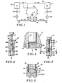
- the reaction injection molding system schematically shown comprises two supply vessels 10 and 11 for containing the reactant liquids A and B, respectively.
- the supply vessels may be fitted with heating elements, stirrers, and the like, and preferably with means for connection to a source of nitrogen or other inert gas under pressure.
- Reactant A is circulated by pump 12 through flow line 13 including valve 14 to inlet 15 of mixhead 16.
- liquid component A circulates through the mixhead, as described in greater detail hereinafter, and exits through port 18 through flow line 19 back to vessel 10.
- Simultaneously component B is circulated by pump 20 through flow line 21 including valve 22 to inlet port 23 in mixhead 16.
- Component B circulates through the mixhead out through exit port 24 and flow line 25 to return to vessel 11.
- the mixhead body includes a longitudinal channel 26 in which ram 17 is disposed with a close slide fit for reciprocation between a first open or upstream position shown in Figure 2 and a second closed or downstream position shown in Figure 3.
- ram 17 When the ram is in its first position, that portion of channel 26 downstream from the ram functions as an impingement mixing chamber, as best shown in Figure 4, the jets of components impinging upon the end of ram 17.
- Component inlet ports 15 and 23 enter the housing and intersect channel 26 preferably at an acute angle between about 45° and 60° relative to the longitudinal axis of the mixhead so as to cause the liquid components to impinge upon the downstream face of ram 17.
- Exit ports 18 and 24 preferably are disposed at angles between about 135° to 120° and are spaced upstream from the inlet ports so as to be in general alignment with the inlet ports, as shown in Figure 1. Straight line alignment is not essential but it is desirable that changes in direction of the fluid flow paths be minimized.
- a recycle flow passage 27 extends through ram 17 so as to connect inlet port 15 and exit port 18 when the ram is in its downstream position shown in Figure 3 to recycle component A.
- a further recycle passage 28 extends through ram 17 to connect inlet port 23 and exit port 24 when the ram is in its downstream position to recycle component B.
- the flow path formed by inlet port 15, recycle passage 27 and exit port 18 preferably lie in one plane and the flow path formed by inlet 23, recycle passage 28 and exit port 24 lie in another parallel plane. As shown, these planes are spaced apart on opposite sides of the longitudinal axis of the ram so as to prevent any intersection of the flow paths and mixing of the components during recirculation.
- This displacement of inlet ports 15 and 23 creates a swirl effect.
- the flow paths are shown and described as lying in parallel planes, this obviously is not mandatory, so long as the flow paths do not intersect.
- the swirl effect can be reduced by altering the alignment of the inlet ports.
- ram 17 be kept in alignment so as to mate recycle passages 27 and 28 with the respective inlet and exit ports.
- One manner in which ram 17 may be prevented from rotating is to provide a longitudinal slot 29 in the ram which functions as a keyway for a transverse pin 30 supported in the body on opposite sides of the channel.
- the cross section of the ram 17 and channel 26 may be some geometrical configuration other than circular.
- the nozzle openings from the inlet ports 15 and 23 be adjustable to help balance the momentum of each liquid component stream. This may be accomplished by screws 31 and 32 extending into ports 15 and 23, respectively, as shown in Figure 5. Variation of the nozzles may also be accomplished by use of orifice inserts with different diameter openings.
- the flow of components should be continuous. This is not possible because of the valving effect of the ram.
- the interruption of flow is during the period in which the ram is moved between the positions shown in Figures 2 and 3. During this short time neither injection of components from the inlet ports nor recirculation is occurring. This dead travel time is preferably minimized by locating the recycle flow passages 27 and 28 close to the downstream end of the ram.
- RIM system and mixhead are described in terms of the use of two reactive liquid components, it will be readily understood that the system and mixhead design are adaptable to the use of three or more components.
- Additional inlet ports, exit ports, and recycle passages are provided as necessary, along with additional supply vessels, flow lines, etc.
- the respective inlet and exit ports are spaced approximately equally around the periphery of the mixhead channel, although if desired the inlet ports may be on one side of the channel and the exit ports on the other, both spaced apart to avoid intersection, as described.
Landscapes
- Engineering & Computer Science (AREA)
- Mechanical Engineering (AREA)
- Chemical & Material Sciences (AREA)
- Chemical Kinetics & Catalysis (AREA)
- Processing And Handling Of Plastics And Other Materials For Molding In General (AREA)
- Injection Moulding Of Plastics Or The Like (AREA)
- Supporting Of Heads In Record-Carrier Devices (AREA)
- Paper (AREA)
- Lining Or Joining Of Plastics Or The Like (AREA)
Claims (6)
caractérisée en ce que les orifices de sortie (18, 24) communiquent avec le couloir, le premier orifice de sortie (18) étant disposé en amont par rapport au premier orifice d'entrée (15) et sensiblement sur le côté du couloir situé à l'opposé de ce premier orifice d'entrée (15), tandis que l'autre orifice de sortie (24) est disposé en amont de l'orifice correspondant d'entrée (23) et sensiblement sur le côté du couloir situé à l'opposé de l'orifice correspondant d'entrée (23), les passages de recyclage (27, 28) étant ménagés dans le piston-plongeur (17).
Priority Applications (1)
| Application Number | Priority Date | Filing Date | Title |
|---|---|---|---|
| AT82901689T ATE36122T1 (de) | 1981-04-28 | 1982-04-16 | Presskolbenmischkopf mit hochdruckzurueckfuehrung. |
Applications Claiming Priority (2)
| Application Number | Priority Date | Filing Date | Title |
|---|---|---|---|
| US06/258,280 US4473531A (en) | 1981-04-28 | 1981-04-28 | Rim mixhead with high pressure recycle |
| US258280 | 1994-06-10 |
Publications (3)
| Publication Number | Publication Date |
|---|---|
| EP0077380A1 EP0077380A1 (fr) | 1983-04-27 |
| EP0077380A4 EP0077380A4 (fr) | 1985-10-24 |
| EP0077380B1 true EP0077380B1 (fr) | 1988-08-03 |
Family
ID=22979889
Family Applications (1)
| Application Number | Title | Priority Date | Filing Date |
|---|---|---|---|
| EP19820901689 Expired EP0077380B1 (fr) | 1981-04-28 | 1982-04-16 | Tete melangeuse de moulage par injection a reaction (rim) avec recyclage sous haute pression |
Country Status (11)
| Country | Link |
|---|---|
| US (1) | US4473531A (fr) |
| EP (1) | EP0077380B1 (fr) |
| JP (1) | JPS5833440A (fr) |
| BE (1) | BE892987A (fr) |
| CA (1) | CA1177617A (fr) |
| DE (1) | DE3278852D1 (fr) |
| ES (1) | ES511754A0 (fr) |
| IT (1) | IT1147938B (fr) |
| NO (1) | NO824382L (fr) |
| PT (1) | PT74810B (fr) |
| WO (1) | WO1982003797A1 (fr) |
Cited By (2)
| Publication number | Priority date | Publication date | Assignee | Title |
|---|---|---|---|---|
| DE29512078U1 (de) * | 1995-07-26 | 1996-03-07 | Macan, Zlatko, 81243 München | Misch- und Dosiervorrichtung für Silikon |
| DE19960202C2 (de) * | 1999-12-14 | 2003-03-20 | Zsolt Herbak | Vorrichtung zum Mischen von viskosen Flüssigkeiten |
Families Citing this family (31)
| Publication number | Priority date | Publication date | Assignee | Title |
|---|---|---|---|---|
| DE3477153D1 (en) * | 1983-09-03 | 1989-04-20 | Hennecke Gmbh Maschf | Multiple nozzle bringing together at least two free-flowing reactants for the preparation of a free-flowing reaction mixture which reacts into plastic, in particular into foamed plastic |
| DE3431112A1 (de) * | 1984-08-24 | 1986-03-06 | Spühl AG, St. Gallen | Mischkopf zur reaktiven mischung von kunststoff-komponenten |
| IT1196275B (it) * | 1984-10-01 | 1988-11-16 | Afros Spa | Testa miscelatrice a camera mobile |
| US5201580A (en) * | 1985-07-12 | 1993-04-13 | Krauss Maffei Aktiengesellschaft | Impingement mixing device |
| DE3525004A1 (de) * | 1985-07-12 | 1987-01-22 | Krauss Maffei Ag | Vorrichtung zum erzeugen eines vorzugsweise chemisch reaktionsfaehigen gemisches aus mindestens zwei kunststoffkomponenten |
| IT1214531B (it) * | 1986-09-25 | 1990-01-18 | Afros Spa | Apparecchiatura di miscelazione ad alta pressione. |
| DE3820810A1 (de) * | 1988-06-20 | 1989-12-21 | Krauss Maffei Ag | Vorrichtung zum mischen von wenigstens zwei reaktiven kunststoffkomponenten |
| US5082437A (en) * | 1989-04-13 | 1992-01-21 | Sumitomo Rubber Industries, Ltd. | Reaction injection machine utilizing a plurality of reactant liquids |
| US5445781A (en) * | 1991-08-28 | 1995-08-29 | Centro Sviluppo Settori Impiego S.R.L. | Process for the injection molding of non-precatalyzed polymerizable resins at high-pressure and flow |
| JP2553287B2 (ja) * | 1992-07-29 | 1996-11-13 | 幸彦 唐澤 | 乳化装置 |
| US5498151A (en) * | 1993-05-05 | 1996-03-12 | Nennecker; Gunter H. | Mixing head for molding machine |
| US5423488A (en) * | 1994-05-11 | 1995-06-13 | Davidson Textron Inc. | Spray apparatus for mixing, atomizing and spraying foam forming components |
| US5562883A (en) * | 1995-05-05 | 1996-10-08 | Davidson Textron Inc. | Solvent flush reaction injection molding mixhead |
| DE69809119T2 (de) * | 1997-05-22 | 2003-03-27 | Afros S.P.A., Caronno Pertusella | Selbstreinigende Mischvorrichtung und Verfahren zur Herstellung von Polyurethane Mischungen |
| AT408344B (de) * | 1997-08-22 | 2001-10-25 | Gerhard Melcher | Verfahren zur mobilen herstellung von überwiegend anorganischen schäumen und entsprechende mobile geräte |
| US6207719B1 (en) * | 1998-08-19 | 2001-03-27 | Dennis G. Pardikes | Method and system for preparing ASA emulsion |
| ITMI20030187A1 (it) * | 2003-02-05 | 2004-08-06 | Afros Spa | Apparecchiatura di miscelazione ad alta pressione |
| US7093972B2 (en) * | 2003-06-20 | 2006-08-22 | Mhr, Inc. | Tri-tilt mixing head |
| JP4929591B2 (ja) * | 2004-12-21 | 2012-05-09 | 東洋製罐株式会社 | スパウト |
| JP4876457B2 (ja) * | 2005-07-04 | 2012-02-15 | 大日本印刷株式会社 | 注出具、注出具付き容器 |
| JP4876458B2 (ja) * | 2005-07-04 | 2012-02-15 | 大日本印刷株式会社 | 注出具、注出具付き容器 |
| US7810674B2 (en) * | 2005-07-26 | 2010-10-12 | Millipore Corporation | Liquid dispensing system with enhanced mixing |
| US7950547B2 (en) | 2006-01-12 | 2011-05-31 | Millipore Corporation | Reservoir for liquid dispensing system with enhanced mixing |
| KR100833679B1 (ko) * | 2006-11-07 | 2008-05-29 | 포항공과대학교 산학협력단 | 극소량 액체의 혼합 장치 및 그 혼합 방법 |
| DE102007023239B4 (de) * | 2007-05-18 | 2010-03-11 | Frimo Group Gmbh | Verfahren und Vorrichtung zur Herstellung eines Polyurethans aus zumindest zwei flüssigen Ausgangskomponenten |
| DE102009036537B3 (de) * | 2009-08-07 | 2011-02-17 | Cannon Deutschland Gmbh | Vorrichtung und Verfahren zur Emulgierung von Flüssigkeiten |
| EP2338665B1 (fr) | 2009-12-22 | 2017-08-30 | Fundacion Inasmet | Procédé et dispositif pour polymériser les lactames dans des moules |
| PT106166A (pt) | 2012-02-20 | 2013-08-20 | Univ Do Porto | Câmara de mistura de jatos opostos para mistura de fluidos com diferentes débitos mássicos |
| US10407234B2 (en) * | 2012-09-05 | 2019-09-10 | Henkel IP & Holding GmbH | Two component fluid metering and mixing system |
| US10046494B2 (en) | 2016-09-07 | 2018-08-14 | BetaJet, LLC | Small format reaction injection molding machines and components for use therein |
| JP7200112B2 (ja) * | 2017-08-09 | 2023-01-06 | 株式会社 資生堂 | 吐出容器、該吐出容器を有するカスタマイズ吐出システム、該吐出容器における吐出制御方法 |
Family Cites Families (10)
| Publication number | Priority date | Publication date | Assignee | Title |
|---|---|---|---|---|
| CA943721A (en) * | 1970-02-20 | 1974-03-19 | Krauss-Maffei Aktiengesellschaft | Device for feeding flowable material to a cavity |
| US3960506A (en) * | 1970-06-20 | 1976-06-01 | Bayer Aktiengesellschaft | Apparatus for producing homogeneous materials or foam from at least two inter-reacting components |
| DE2145547C3 (de) * | 1971-09-11 | 1974-07-11 | Heinrich 3111 Gross Liedern Clasen | Gegenstrominjektionsmischkopf |
| DE2631588B2 (de) * | 1976-07-14 | 1979-06-07 | Elastogran Maschinenbau Gmbh & Co, 8021 Strasslach | Vorrichtung zur Herstellung von Kunststoffen, insbesondere Polyurethan, aus mindestens zwei reaktiven Komponenten |
| US4108606A (en) * | 1976-12-22 | 1978-08-22 | The Upjohn Company | Universal coupling for reaction injection molding machine |
| US4099919A (en) * | 1976-12-22 | 1978-07-11 | The Upjohn Company | Stem adjustment seal for reaction injection molding machine |
| US4082512A (en) * | 1976-12-22 | 1978-04-04 | The Upjohn Company | Mixing head for a reaction injection molding machine |
| US4189070A (en) * | 1978-02-03 | 1980-02-19 | The Regents Of The University Of Minnesota | Reaction injection molding machine |
| DE2837424A1 (de) * | 1978-08-28 | 1980-03-20 | Bayer Ag | Vorrichtung zum herstellen eines insbesondere schaumstoff bildenden reaktionsgemisches aus fliessfaehigen komponenten |
| CA1176786A (fr) * | 1979-06-22 | 1984-10-23 | Manfred Kelterbaum | Methode et dispositif injecteur-melangeur a contre-courant de deux agents plastiques fluides a reaction reciproque |
-
1981
- 1981-04-28 US US06/258,280 patent/US4473531A/en not_active Expired - Fee Related
-
1982
- 1982-03-31 CA CA000400191A patent/CA1177617A/fr not_active Expired
- 1982-04-07 JP JP57057975A patent/JPS5833440A/ja active Pending
- 1982-04-16 EP EP19820901689 patent/EP0077380B1/fr not_active Expired
- 1982-04-16 DE DE8282901689T patent/DE3278852D1/de not_active Expired
- 1982-04-16 WO PCT/US1982/000498 patent/WO1982003797A1/fr not_active Ceased
- 1982-04-27 ES ES511754A patent/ES511754A0/es active Granted
- 1982-04-27 PT PT7481082A patent/PT74810B/pt unknown
- 1982-04-27 BE BE0/207936A patent/BE892987A/fr not_active IP Right Cessation
- 1982-04-28 IT IT4830082A patent/IT1147938B/it active
- 1982-12-27 NO NO82824382A patent/NO824382L/no unknown
Cited By (2)
| Publication number | Priority date | Publication date | Assignee | Title |
|---|---|---|---|---|
| DE29512078U1 (de) * | 1995-07-26 | 1996-03-07 | Macan, Zlatko, 81243 München | Misch- und Dosiervorrichtung für Silikon |
| DE19960202C2 (de) * | 1999-12-14 | 2003-03-20 | Zsolt Herbak | Vorrichtung zum Mischen von viskosen Flüssigkeiten |
Also Published As
| Publication number | Publication date |
|---|---|
| CA1177617A (fr) | 1984-11-13 |
| ES8304805A1 (es) | 1983-03-16 |
| PT74810A (en) | 1982-05-01 |
| EP0077380A1 (fr) | 1983-04-27 |
| DE3278852D1 (en) | 1988-09-08 |
| US4473531A (en) | 1984-09-25 |
| BE892987A (fr) | 1982-08-16 |
| IT1147938B (it) | 1986-11-26 |
| EP0077380A4 (fr) | 1985-10-24 |
| ES511754A0 (es) | 1983-03-16 |
| JPS5833440A (ja) | 1983-02-26 |
| PT74810B (en) | 1983-12-29 |
| IT8248300A0 (it) | 1982-04-28 |
| NO824382L (no) | 1982-12-27 |
| WO1982003797A1 (fr) | 1982-11-11 |
Similar Documents
| Publication | Publication Date | Title |
|---|---|---|
| EP0077380B1 (fr) | Tete melangeuse de moulage par injection a reaction (rim) avec recyclage sous haute pression | |
| CA1209104A (fr) | Dispositif melangeur-debiteur des composantes d'un contenant compartimente | |
| CA1268014A (fr) | Tete de melange sous haute pression avec clapet d'injection d'agent reactif | |
| US4239732A (en) | High velocity mixing system | |
| US4917502A (en) | Nozzle for the mixing of at least two flowable reaction components and process for operating such nozzle | |
| US4440500A (en) | High pressure impingement mixing apparatus | |
| CA1198414A (fr) | Tete melangeuse | |
| US5093084A (en) | Apparatus for the continuous preparation of a liquid reaction mixture from two fluid reactants | |
| JPS63104679A (ja) | 液体の混合吐出又は噴出方法とその装置 | |
| US4600312A (en) | Impingement mix-head for rim process | |
| EP1560687B1 (fr) | Procede et appareil de melange par coinjection | |
| US4452919A (en) | High velocity mixing method | |
| US5143946A (en) | Process and apparatus for the production of a flowable reaction mixture from at least two flowable reactive components | |
| US4469130A (en) | Adjustable orifice for reaction injection molding | |
| US5201580A (en) | Impingement mixing device | |
| EP0132443A1 (fr) | Dispositif et procédé mélangeurs par injection à haute pression | |
| US7240689B2 (en) | Multiple component mixing head | |
| EP0137706B1 (fr) | Equipement pour mélange de réactants liquides | |
| US4065106A (en) | Mixing head for machines for producing multicomponent plastics | |
| JPH07115373B2 (ja) | 少なくとも2つのプラスチツク成分を混合するための混合ヘツド | |
| JPS63248428A (ja) | 液体の混合噴出方法とその装置 | |
| JPH0352321B2 (fr) | ||
| JPH02261608A (ja) | 多成分合成樹脂混合装置 | |
| JPS6341723B2 (fr) | ||
| JPH0119326B2 (fr) |
Legal Events
| Date | Code | Title | Description |
|---|---|---|---|
| PUAI | Public reference made under article 153(3) epc to a published international application that has entered the european phase |
Free format text: ORIGINAL CODE: 0009012 |
|
| AK | Designated contracting states |
Designated state(s): AT CH DE FR GB LI LU NL SE |
|
| 17P | Request for examination filed |
Effective date: 19830415 |
|
| 17Q | First examination report despatched |
Effective date: 19861111 |
|
| GRAA | (expected) grant |
Free format text: ORIGINAL CODE: 0009210 |
|
| AK | Designated contracting states |
Kind code of ref document: B1 Designated state(s): AT CH DE FR GB LI LU NL SE |
|
| PG25 | Lapsed in a contracting state [announced via postgrant information from national office to epo] |
Ref country code: SE Effective date: 19880803 Ref country code: NL Effective date: 19880803 |
|
| REF | Corresponds to: |
Ref document number: 36122 Country of ref document: AT Date of ref document: 19880815 Kind code of ref document: T |
|
| REF | Corresponds to: |
Ref document number: 3278852 Country of ref document: DE Date of ref document: 19880908 |
|
| ET | Fr: translation filed | ||
| NLV1 | Nl: lapsed or annulled due to failure to fulfill the requirements of art. 29p and 29m of the patents act | ||
| PGFP | Annual fee paid to national office [announced via postgrant information from national office to epo] |
Ref country code: FR Payment date: 19890427 Year of fee payment: 8 |
|
| PGFP | Annual fee paid to national office [announced via postgrant information from national office to epo] |
Ref country code: AT Payment date: 19890428 Year of fee payment: 8 |
|
| PG25 | Lapsed in a contracting state [announced via postgrant information from national office to epo] |
Ref country code: LU Free format text: LAPSE BECAUSE OF NON-PAYMENT OF DUE FEES Effective date: 19890430 |
|
| PGFP | Annual fee paid to national office [announced via postgrant information from national office to epo] |
Ref country code: GB Payment date: 19890430 Year of fee payment: 8 |
|
| PGFP | Annual fee paid to national office [announced via postgrant information from national office to epo] |
Ref country code: DE Payment date: 19890511 Year of fee payment: 8 |
|
| PLBE | No opposition filed within time limit |
Free format text: ORIGINAL CODE: 0009261 |
|
| STAA | Information on the status of an ep patent application or granted ep patent |
Free format text: STATUS: NO OPPOSITION FILED WITHIN TIME LIMIT |
|
| PGFP | Annual fee paid to national office [announced via postgrant information from national office to epo] |
Ref country code: CH Payment date: 19890622 Year of fee payment: 8 |
|
| 26N | No opposition filed | ||
| PG25 | Lapsed in a contracting state [announced via postgrant information from national office to epo] |
Ref country code: GB Effective date: 19900416 Ref country code: AT Effective date: 19900416 |
|
| PG25 | Lapsed in a contracting state [announced via postgrant information from national office to epo] |
Ref country code: LI Effective date: 19900430 Ref country code: CH Effective date: 19900430 |
|
| GBPC | Gb: european patent ceased through non-payment of renewal fee | ||
| PG25 | Lapsed in a contracting state [announced via postgrant information from national office to epo] |
Ref country code: FR Effective date: 19901228 |
|
| REG | Reference to a national code |
Ref country code: CH Ref legal event code: PL |
|
| PG25 | Lapsed in a contracting state [announced via postgrant information from national office to epo] |
Ref country code: DE Effective date: 19910101 |
|
| REG | Reference to a national code |
Ref country code: FR Ref legal event code: ST |