EP0077602A2 - Mechanical fire suppressant release station - Google Patents
Mechanical fire suppressant release station Download PDFInfo
- Publication number
- EP0077602A2 EP0077602A2 EP82303503A EP82303503A EP0077602A2 EP 0077602 A2 EP0077602 A2 EP 0077602A2 EP 82303503 A EP82303503 A EP 82303503A EP 82303503 A EP82303503 A EP 82303503A EP 0077602 A2 EP0077602 A2 EP 0077602A2
- Authority
- EP
- European Patent Office
- Prior art keywords
- mechanical
- electrical
- mechanical energy
- storing
- generator
- Prior art date
- Legal status (The legal status is an assumption and is not a legal conclusion. Google has not performed a legal analysis and makes no representation as to the accuracy of the status listed.)
- Withdrawn
Links
Images
Classifications
-
- A—HUMAN NECESSITIES
- A62—LIFE-SAVING; FIRE-FIGHTING
- A62C—FIRE-FIGHTING
- A62C35/00—Permanently-installed equipment
-
- A—HUMAN NECESSITIES
- A62—LIFE-SAVING; FIRE-FIGHTING
- A62C—FIRE-FIGHTING
- A62C37/00—Control of fire-fighting equipment
- A62C37/36—Control of fire-fighting equipment an actuating signal being generated by a sensor separate from an outlet device
Definitions
- This invention relates to fire suppressant devices that employ electrically fired initiators. More particularly, it is concerned with a fire suppressant device in which a mechanical initiating signal can be transferred via mechanical linkage from a remote station to a mechanical-electrical actuator in order to generate an electrical signal for firing an electrically fired initiator.
- fire suppressant apparatus that include electrically fired initiators have required an independent source of electrical energy, and electrical conducting wires connecting the initiator, the source of electrical energy, and a remote actuating station.
- previous systems have proven generally satisfactory in operation, such systems are dependent on the integrity of the electrical conducting wire, and of the independent source of electrical energy.
- Such dependence on the integrity of electrical systems is considered by some marine engineers to be an undesirable trait for fire suppressant apparatus designed for shipboard use.
- an electrically fired detonation initiator in conjunction with a frangible seal is considered to be a superior system from the standpoint of instantaneous release of fire suppressant.
- a fire suppressant apparatus including a frangible seal and an electrically fired initiator that is not dependent on an external source of electrical energy, and reduces to a minimum the requirement for electrical conducting wire, would be a decided advantage.
- the apparatus hereof includes a frangible seal and electrically fired initiator, but is independent of external electrical energy sources, and reduces to a minimum the requirement for electrical conducting wires.
- the fire suppressant apparatus in accordance with. t he present invention broadly includes a hermetically sealed fire suppressant substance container, an electrically fired initiator for selectively rupturing the seal of the container, a mechanical-electrical actuator for generating an electrical signal sufficient to fire the initiator, a remote release station, and a mechanical linkage connecting the release station and the mechanical-electrical actuator.
- the mechanical-electrical . actuator is located adjacent to the suppressant container and in close proximity to the electrically fired initiator.
- the mechanical linkage includes a cable and pulley assembly
- the mechanical-electrical actuator includes a selectively rotatable pulley, a gear assembly operatively connected to the pulley, a spring for storing the mechanical energy derived from the rotation of the pulley and gear assembly, and a direct current generator for converting mechancial energy stored by the spring to electrical energy.
- a fire suppressant apparatus 10 in accordance with the invention broadly includes a hazard suppressant container 12 including an electrically fired initiator 14, a mechanical-electrical actuator 16, a remote operating station 18 and a mechanical linkage 20 connecting the station 18 and the actuator 16.
- the container 12 is conventional and has an externally threaded, tubular outlet 22.
- An internally threaded outlet extension 24 is threaded onto outlet 22.
- An annular mating washer 26 is interposed between the tubular outlet 22 and the outlet extension 24.
- the end 28 of outlet 22 is sealed by a transversely extending rupturable metallic burst element or membrane 30.
- Membrane 30 is a relatively thin, frangible diaphragm characterized by the quality of being resistant to rupture until a predetermined pressure is exceeded, but will undergo rupture upon application of a force above the pressure for which it was designed.
- Membrane 30 is further distinguished by the circular, concave-convex, dome-shaped configuration of the central portion thereof.
- the membrane is positioned over end 28 of outlet 22 with its concave face directed towards the container 12.
- the outlet extension 24 includes a bell-shaped suppressant distributor head 32.
- the initiator 14 includes a detonator 34, a detonator-receiving receptacle 36 and connection wires 38.
- the initiator 14 is threadably received within the outlet extension 24 such that one end 40 of the detonator 36 is in adjacent or abutting relationship with the convex face 42 of the membrane 30.
- the mechanical-electrical actuator 16 is connected to the fire suppressant container 12, adjacent to the detonator receptacle 36.
- the actuator 16 includes a rotatable, cantilever- mounted pulley 44, a gear assembly 46 operatively connected to the pulley 44, a drive spring 48 and a direct current generator 50.
- a ball and detent assembly 52 comprising a spring biased ball 54 mounted on the housing 56 of the actuator 16 and a machined recess 58 on the face of the pulley 44, is positioned to hold the pulley 44 in a rest position.
- the gear assembly 46 includes a driving gear 60 (see Fig. 3) and a smaller driven gear 62.
- Driven gear 62 is mounted on the armature 64 of the generator 50, whereas pulley 44 and gear 60 are mounted for rotation about a fixed shaft 66.
- the drive spring 48 is a coil spring, and is received within an enclosure 68 that projects from the generator housing 50.
- the internal end 70 of the drive spring 48 is operably connected to the armature 64 of the generator 50, and the external end 72 of the spring 48 is secured to the enclosure 68.
- the circumferential edge 74 of the driving gear 60 includes an untoothed gap or notch 76.
- the circumference of the driving gear 60 is preferably equal to or greater than about one and one quarter inches.
- the gear ratio of the driving gear to the driven gear is preferably from about 5:1 to about 10:1.
- the mechanical linkage 20 includes a cable assembly 78 and a plurality of corner pulleys 80.
- the cable asscmbly 78 includes a cable 82 shiftably received in a cable carrying conduit 84.
- the actuator end of cable 82 extends through a suitable gasketed elbow fitting 86 into housing 56 and is operatively connected to pulley 44.
- the opposite end of cable 82 extends through an apertured plate 88 affixed to bulkhead 90 and is coupled to an end fitting 92; the latter is secured to a handle 94 as best seen in Fig. 2.
- a brass sleeve (not shown) may advantageously be crimped on the cable 82, and positioned on the cable 82 so as to abut the outer surface of the actuator housing 56 when the cable 82 is fully wound on the pulley 44.
- fire suppressant apparatus 10 of the present invention may be interconnected with a conventional, automatic, hazard-sensing electronic firing mechanism 100 by wires 102.
- the wires 102 are received within the actuator housing 56 through fluid tight gasket 104.
- wires 38, 96 are completely enclosed within the actuator housing 56 and receptacle 36.
- the container 12 can be mounted by mounts 106 to a bulkhead 108 of the space to be protected, such as an engine room 110 of a ship 112 having an engine 114.
- the operator releases fire suppressant substance (not shown) from the container 12 by manually grasping the handle 94 and pulling the handle 94 away from its rest position abutting the plate 88, and thereby shifting the cable 82 within the conduit 84. Shifting of the cable 82 in turn rotates the pulley 44 and the driving gear 60 in a counterclockwise rotation as depicted in Fig. 3. Rotation of the driving gear 60 rotates the driven gear 62 and the . drive coil spring 48 is thereby tensioned and stores a quantum of mechanical energy derived from rotation of the gear assembly 46.
- Rotation of the gears 60, 62 proceeds as described until the gear 60 reaches a point (almost at the end of a full 360° revolution thereof) when gear 62 clears the peripheral teeth of the gear 60 and enters the notch 76. At this point the gear 62 and thereby armature 64 are free to rotate independently of gear 60, and rapidly do so under the influence of the tensioned drive spring 48. Such rotation of the armature 64 converts the stored mechanical energy into electrical energy and creates an electrical signal having the characteristics necessary to fire the detonator 34.
- Figure 4 depicts a typical waveform generated by the actuator 16.
- the waveform includes a rapidly rising leading edge 116, a generally level, intermediate portion 118, and a gradually descending, parabolic trailing edge 120.
- the cable 82 will not be wrapped around the pulley 44 once the handle 94 has been shifted and the actuator 16 thereby operated.
- the actuator 16 will not be operable until the cable 82 is manually rewound around the pulley 44.
- the handle 94 will remain in a shifted position until the cable 82 is rewound,-and will serve as a "tell-tale" sign that the fire suppressant has been discharged from the container 12.
- the voltage generated by the generator 50 will rapidly rise to a level of about 36 volts and will maintain that voltage for a time span of two to three seconds.
- a conventional initiator 14, such as the Elll DuPont initiator requires 500 milliamps applied for 2 milliseconds to fire. Since the resistance of the Elll initiator is about 1 ohm, those skilled in the art will realize that the actuator 16 provides a signal over 30 times greater than that required to fire an initiator, and for a period of time well in excess of that required for initiation. Thus it will be seen that the electrical signal provided by the actuator 16 is more than ample to insure consistent, predictable firing of the initiator 14, and one actuator 16 can be used to fire a plurality of initiators 14 if desired.
Landscapes
- Health & Medical Sciences (AREA)
- Public Health (AREA)
- Business, Economics & Management (AREA)
- Emergency Management (AREA)
- Fire-Extinguishing By Fire Departments, And Fire-Extinguishing Equipment And Control Thereof (AREA)
- Pharmaceuticals Containing Other Organic And Inorganic Compounds (AREA)
Abstract
An improved, mechanically actuated electrical detonator type fire suppression apparatus is provided which is particularly suited for use in marine applications or in other situations where complete dependence upon an external electrical circuit is to be avoided. Preferably, the apparatus hereof includes, in addition to the usual fire suppressant container and rupturable seal, an electrical generator coupled to the detonator and a mechanical linkage assembly coupled to the generator for selective operation of the latter. An operator handle forms a part of the linkage assembly and is shiftable so as to initiate operation of the generator with consequent charge detonation. In particularly preferred forms, a gear and spring assembly is coupled between the linkage and generator and is operable to initially store mechanical energy followed by rapid release thereof in order to generate an operating signal having the proper electrical characteristics.
Description
- This invention relates to fire suppressant devices that employ electrically fired initiators. More particularly, it is concerned with a fire suppressant device in which a mechanical initiating signal can be transferred via mechanical linkage from a remote station to a mechanical-electrical actuator in order to generate an electrical signal for firing an electrically fired initiator.
- It is known in the art to hermetically seal the outlet of a fire suppressant container with a frangible diaphragm or membrane, and to use a selectively actuatable detonating component to selectively rupture the frangible membrane and thereby initiate the operation of the fire suppressant apparatus (see, e.g. U.S. Patent No. 3,762,479). This type of fire suppressant apparatus is particularly suitable when instantaneous release of a fire suppressant is desired, in areas such as the engine compartment of a car or the bilge of a boat which fend to fill with fumes from the engine, and are nb.t readily accessible. Heretofore, however, fire suppressant apparatus that include electrically fired initiators have required an independent source of electrical energy, and electrical conducting wires connecting the initiator, the source of electrical energy, and a remote actuating station. Although previous systems have proven generally satisfactory in operation, such systems are dependent on the integrity of the electrical conducting wire, and of the independent source of electrical energy. Such dependence on the integrity of electrical systems is considered by some marine engineers to be an undesirable trait for fire suppressant apparatus designed for shipboard use. Notwithstanding this consideration, an electrically fired detonation initiator in conjunction with a frangible seal is considered to be a superior system from the standpoint of instantaneous release of fire suppressant. A fire suppressant apparatus including a frangible seal and an electrically fired initiator that is not dependent on an external source of electrical energy, and reduces to a minimum the requirement for electrical conducting wire, would be a decided advantage.
- The problems oulined above are in large measure solved by the fire suppressant apparatus in accordance with the present invention. That is to say, the apparatus hereof includes a frangible seal and electrically fired initiator, but is independent of external electrical energy sources, and reduces to a minimum the requirement for electrical conducting wires.
- , The fire suppressant apparatus in accordance with.the present invention broadly includes a hermetically sealed fire suppressant substance container, an electrically fired initiator for selectively rupturing the seal of the container, a mechanical-electrical actuator for generating an electrical signal sufficient to fire the initiator, a remote release station, and a mechanical linkage connecting the release station and the mechanical-electrical actuator.
- Preferably the mechanical-electrical . actuator is located adjacent to the suppressant container and in close proximity to the electrically fired initiator.
- In particularly preferred forms, the mechanical linkage includes a cable and pulley assembly, and the mechanical-electrical actuator includes a selectively rotatable pulley, a gear assembly operatively connected to the pulley, a spring for storing the mechanical energy derived from the rotation of the pulley and gear assembly, and a direct current generator for converting mechancial energy stored by the spring to electrical energy.
-
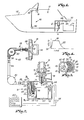
- Figure 1 is a schematic view of a boat depicting a fire suppressant container mounted in the engine compartment, with an actuator in accordance with the present invention mounted adjacent to the fire suppressant container and connected by a cable and pulley mechanism to a remote operating station;
- Fig. 2 is a fragmentary view partially in schematic form and partially in section, depicting an overall system having an actuator, fire suppressant apparatus, cable and pulley assembly, and remote pull station; .
- Fig. 3 is a sectional view taken along the line of 3-3 of Fig. 1; and
- Fig. 4 illustrates the electrical wave form generated by the actuator hereof.
- Referring to the drawing, a fire
suppressant apparatus 10 in accordance with the invention broadly includes a hazardsuppressant container 12 including an electrically firedinitiator 14, a mechanical-electrical actuator 16, aremote operating station 18 and amechanical linkage 20 connecting thestation 18 and theactuator 16. - The
container 12 is conventional and has an externally threaded,tubular outlet 22. An internally threadedoutlet extension 24 is threaded ontooutlet 22. Anannular mating washer 26 is interposed between thetubular outlet 22 and theoutlet extension 24. Theend 28 ofoutlet 22 is sealed by a transversely extending rupturable metallic burst element ormembrane 30.Membrane 30 is a relatively thin, frangible diaphragm characterized by the quality of being resistant to rupture until a predetermined pressure is exceeded, but will undergo rupture upon application of a force above the pressure for which it was designed.Membrane 30 is further distinguished by the circular, concave-convex, dome-shaped configuration of the central portion thereof. The membrane is positioned overend 28 ofoutlet 22 with its concave face directed towards thecontainer 12. Theoutlet extension 24 includes a bell-shapedsuppressant distributor head 32. - The
initiator 14 includes adetonator 34, a detonator-receivingreceptacle 36 andconnection wires 38. Theinitiator 14 is threadably received within theoutlet extension 24 such that oneend 40 of thedetonator 36 is in adjacent or abutting relationship with theconvex face 42 of themembrane 30. - The mechanical-
electrical actuator 16 is connected to the firesuppressant container 12, adjacent to thedetonator receptacle 36. Theactuator 16 includes a rotatable, cantilever- mountedpulley 44, agear assembly 46 operatively connected to thepulley 44, adrive spring 48 and a directcurrent generator 50. A ball anddetent assembly 52, comprising a springbiased ball 54 mounted on thehousing 56 of theactuator 16 and amachined recess 58 on the face of thepulley 44, is positioned to hold thepulley 44 in a rest position. - The
gear assembly 46 includes a driving gear 60 (see Fig. 3) and a smaller drivengear 62.Driven gear 62 is mounted on thearmature 64 of thegenerator 50, whereaspulley 44 andgear 60 are mounted for rotation about afixed shaft 66. - The
drive spring 48 is a coil spring, and is received within anenclosure 68 that projects from thegenerator housing 50. Theinternal end 70 of thedrive spring 48 is operably connected to thearmature 64 of thegenerator 50, and theexternal end 72 of thespring 48 is secured to theenclosure 68. - The
circumferential edge 74 of thedriving gear 60 includes an untoothed gap or notch 76. The circumference of thedriving gear 60 is preferably equal to or greater than about one and one quarter inches. The gear ratio of the driving gear to the driven gear is preferably from about 5:1 to about 10:1. - The
mechanical linkage 20 includes acable assembly 78 and a plurality ofcorner pulleys 80. The cable asscmbly 78 includes acable 82 shiftably received in acable carrying conduit 84. - The actuator end of
cable 82 extends through a suitable gasketed elbow fitting 86 intohousing 56 and is operatively connected topulley 44. The opposite end ofcable 82 extends through anapertured plate 88 affixed to bulkhead 90 and is coupled to anend fitting 92; the latter is secured to ahandle 94 as best seen in Fig. 2. - A brass sleeve (not shown) may advantageously be crimped on the
cable 82, and positioned on thecable 82 so as to abut the outer surface of theactuator housing 56 when thecable 82 is fully wound on thepulley 44. - The
generator 50 is connected byoutput wires 96 to theinitiator wires 38. Ablocking diode 98 is interposed on oneoutput wire 96. As is depicted in Fig. 2, firesuppressant apparatus 10 of the present invention may be interconnected with a conventional, automatic, hazard-sensingelectronic firing mechanism 100 bywires 102. Thewires 102 are received within theactuator housing 56 through fluidtight gasket 104. - It will be noted that the
wires actuator housing 56 andreceptacle 36. - The
container 12 can be mounted bymounts 106 to abulkhead 108 of the space to be protected, such as anengine room 110 of aship 112 having anengine 114. - % In operation of
apparatus 10, the operator releases fire suppressant substance (not shown) from thecontainer 12 by manually grasping thehandle 94 and pulling thehandle 94 away from its rest position abutting theplate 88, and thereby shifting thecable 82 within theconduit 84. Shifting of thecable 82 in turn rotates thepulley 44 and thedriving gear 60 in a counterclockwise rotation as depicted in Fig. 3. Rotation of thedriving gear 60 rotates the drivengear 62 and the .drive coil spring 48 is thereby tensioned and stores a quantum of mechanical energy derived from rotation of thegear assembly 46. - Rotation of the
gears gear 60 reaches a point (almost at the end of a full 360° revolution thereof) whengear 62 clears the peripheral teeth of thegear 60 and enters the notch 76. At this point thegear 62 and therebyarmature 64 are free to rotate independently ofgear 60, and rapidly do so under the influence of the tensioneddrive spring 48. Such rotation of thearmature 64 converts the stored mechanical energy into electrical energy and creates an electrical signal having the characteristics necessary to fire thedetonator 34. - Figure 4 depicts a typical waveform generated by the
actuator 16. The waveform includes a rapidly risingleading edge 116, a generally level,intermediate portion 118, and a gradually descending,parabolic trailing edge 120. - It will be noted that the
cable 82 will not be wrapped around thepulley 44 once thehandle 94 has been shifted and theactuator 16 thereby operated. Theactuator 16 will not be operable until thecable 82 is manually rewound around thepulley 44. Thehandle 94 will remain in a shifted position until thecable 82 is rewound,-and will serve as a "tell-tale" sign that the fire suppressant has been discharged from thecontainer 12. - In a typical system, the voltage generated by the
generator 50 will rapidly rise to a level of about 36 volts and will maintain that voltage for a time span of two to three seconds. Aconventional initiator 14, such as the Elll DuPont initiator, requires 500 milliamps applied for 2 milliseconds to fire. Since the resistance of the Elll initiator is about 1 ohm, those skilled in the art will realize that theactuator 16 provides a signal over 30 times greater than that required to fire an initiator, and for a period of time well in excess of that required for initiation. Thus it will be seen that the electrical signal provided by theactuator 16 is more than ample to insure consistent, predictable firing of theinitiator 14, and oneactuator 16 can be used to fire a plurality ofinitiators 14 if desired. - Those skilled in the art will also realize that while the
gear assembly 46 is being rotated and mechanical energy is being stored in thedrive spring 48,armature 64 will slowly rotate within thegenerator 50 and will thereby produce an electrical signal of reverse polarity to that generated when thedrive spring 48 is released to rapidly rotate thearmature 64. Blockingdiode 98 interposed in one of thewires 96 prevents the transmission of such reverse polarity electrical signals to thedetonator 34.
Claims (16)
1. Hazard suppression apparatus, comprising: menus for selectively delivering a quantity of a hazard supressing substance;
electrically operated initiation means coupled to said delivery means and actuatable in response to sensing an electrical signal of predetermined electrical characteristics;
means coupled to said initiation means for selectively generating an electrical signal having said predetermined electrical characterisitcs; and
manually shiftable mechanical linkage means coupled to said generating means for operating said generating means to thereby generate said signal in response to shifting of said linkage means.
2. Hazard suppression apparatus, comprising: means for selectively delivering a quantity of a hazard suppressing substance;
electrically operated initiation means coupled to said delivery means and actuatable in response to sensing an electrical signal of predetermined electrical characteristics;
manually operable manipulative means remote from said delivery means;
means operably coupling said manipulative means and said initiating means for delivering an electrical signal of said predetermined characteristics to said initiation means in response to operation of said manipulative means, said coupling means including an electrical signal generator having a shiftable operating member, and a mechanical linkage operatively connecting said member and manipulative means for shifting of the member and consequent generation of said electrical signal upon operation of the manipulative means.
3. Hazard suppression apparatus as in Claim 2, said shiftable operating member being a gear assembly.
4. Hazard suppression apparatus as in Claim 2, including means operatively connected to said shiftable operating member and said generator for storing mechanical energy derived from shifting of said operating member, and for thereafter rapidly releasing said mechanical energy to drive said generator for generation of said electrical signal.
5. Hazard suppression apparatus as in Claim 4, said means for storing mechanical energy comprising a spring.
6. A method for initiating the operation of a hazard suppression apparatus or the like, said apparatus including a container for storing hazard suppressant substance, a frangible seal for sealing said container, and an electrically fired initiator for selectively rupturing said seal, comprising the steps of:
developing a quantum of mechanical energy;
converting said mechanical energy into an electrical signal having characteristics sufficient for firing said initiator; and
applying said signal to said initiator for firing thereof and consequent rupturing . of said frangible seal. .\
7. A method as in Claim 6, including the step of storing said quantum of mechanical energy and thereafter rapidly releasing said mechanical energy.
8. A mechanical-electrical actuator for use with an electrically primed initiator for a fire suppression apparatus or the like comprising:
a selectively rotatable pulley;
a driving gear operatively coupled to said pulley for rotation therewith;
a driven gear operatively coupled to said driving gear;
means operatively coupled to said driven gear for storing mechanical energy; and
means operatively coupled to said energy storing means for converting said mechanical energy to electrical energy.
9. A mechanical-electrical actuator as in Claim 8, said driving gear including structure defining a notch in the circumferential edge thereof.
10. A mechanical-electrical actuator as in Claim 8, said means for storing mechanical energy comprising a spring.
11. A mechanical-electrical actuator as in Claim 8, said converting means comprising a direct current generator.
. 12. A mechanical-electrical actuator as in Claim 8, including means for rotating said pulley from a remote station.
13. A mechanical-electrical actuator for use with an electrically primed initiator for a fire suppression apparatus or the like comprising:
means for storing and thereafter rapidly releasing mechanical energy; and
means operatively connected to said storing and releasing means for converting said mechanical energy to electrical energy.
14. A mechanical-electrical actuator as in Claim 13, said means for storing and rapidly releasing mechanical energy including:
a selectively rotatable pulley;
a driving gear operatively coupled to said pulley for rotation therewith;
a driven gear operatively coupled to said driving gear; and
a spring operatively coupled to said driven gear.
15. A mechanical-electrical actuator as in Claim 13, said converting means comprising a direct current generator.
16. A mechanical-electrical actuator as in Claim 13, including means for rotating said pulley from a remote station.
Applications Claiming Priority (2)
| Application Number | Priority Date | Filing Date | Title |
|---|---|---|---|
| US31271781A | 1981-10-19 | 1981-10-19 | |
| US312717 | 1981-10-19 |
Publications (2)
| Publication Number | Publication Date |
|---|---|
| EP0077602A2 true EP0077602A2 (en) | 1983-04-27 |
| EP0077602A3 EP0077602A3 (en) | 1983-12-14 |
Family
ID=23212692
Family Applications (1)
| Application Number | Title | Priority Date | Filing Date |
|---|---|---|---|
| EP82303503A Withdrawn EP0077602A3 (en) | 1981-10-19 | 1982-07-02 | Mechanical fire suppressant release station |
Country Status (2)
| Country | Link |
|---|---|
| EP (1) | EP0077602A3 (en) |
| JP (1) | JPS5872900A (en) |
Cited By (1)
| Publication number | Priority date | Publication date | Assignee | Title |
|---|---|---|---|---|
| EP2216076A1 (en) * | 2007-03-02 | 2010-08-11 | Ansul, LLC | Fire suppression system and emergency annunciation system |
Family Cites Families (3)
| Publication number | Priority date | Publication date | Assignee | Title |
|---|---|---|---|---|
| FR451547A (en) * | 1912-12-06 | 1913-04-21 | Xavier Flury | Automatic start for internal combustion engines |
| GB1545776A (en) * | 1976-05-11 | 1979-05-16 | Edwards Ltd C | Fire extinguishing devices |
| DE2828789A1 (en) * | 1978-06-30 | 1980-01-03 | Grescha Ges Grefe & Scharf | Fire precaution smoke flap electric release mechanism - has current independently supplied by hand driven dynamo machine |
-
1982
- 1982-07-02 EP EP82303503A patent/EP0077602A3/en not_active Withdrawn
- 1982-09-01 JP JP15248382A patent/JPS5872900A/en active Pending
Cited By (4)
| Publication number | Priority date | Publication date | Assignee | Title |
|---|---|---|---|---|
| EP2216076A1 (en) * | 2007-03-02 | 2010-08-11 | Ansul, LLC | Fire suppression system and emergency annunciation system |
| AU2008223154B2 (en) * | 2007-03-02 | 2014-04-24 | Tyco Fire Products Lp | Fire suppression system and emergency annunciation system |
| US9352176B2 (en) | 2007-03-02 | 2016-05-31 | Tyco Fire Products Lp | Fire suppression system and emergency annunciation system |
| US10398916B2 (en) | 2007-03-02 | 2019-09-03 | Tyco Fire Products Lp | Fire suppression system and emergency annunciation system |
Also Published As
| Publication number | Publication date |
|---|---|
| EP0077602A3 (en) | 1983-12-14 |
| JPS5872900A (en) | 1983-04-30 |
Similar Documents
| Publication | Publication Date | Title |
|---|---|---|
| US1933694A (en) | Electrically controlled actuating device | |
| US3986560A (en) | Fire protection means | |
| US2593432A (en) | Automatically operated radio buoy | |
| US8037823B2 (en) | Networked pyrotechnic actuator incorporating high-pressure bellows | |
| US2721913A (en) | Shock and static pressure discriminating switch | |
| US4482333A (en) | Automatic inflation system | |
| EP0077602A2 (en) | Mechanical fire suppressant release station | |
| US2775939A (en) | Drill mine | |
| US4495849A (en) | Remotely activated cable cutter | |
| US3552495A (en) | Fire extinguisher | |
| US3072415A (en) | Miniature waterproof pressure seal | |
| US4306127A (en) | Corrosion sensor | |
| US3482484A (en) | Cutting tool | |
| US4782470A (en) | Hydrophone with extended operational life | |
| US3780752A (en) | Explosively actuated valve | |
| US3267672A (en) | Gas generating device with initiator insulating means | |
| US5199004A (en) | Sealed acoustical element using conductive epoxy | |
| US4498491A (en) | Thermo-electric valve | |
| US2901997A (en) | Sound generator | |
| US2408816A (en) | Piezoelectric gauge and method of making the same | |
| US4207626A (en) | Acoustic decoy and jammer | |
| US5396845A (en) | Modular fuze | |
| US4457328A (en) | Combined positive seal and repetitive actuation isolation valve | |
| US2961961A (en) | Torpedo exploder mechanism | |
| US5068162A (en) | Reserve activated electrochemical cell |
Legal Events
| Date | Code | Title | Description |
|---|---|---|---|
| PUAI | Public reference made under article 153(3) epc to a published international application that has entered the european phase |
Free format text: ORIGINAL CODE: 0009012 |
|
| AK | Designated contracting states |
Designated state(s): AT BE CH DE FR GB IT LI LU NL SE |
|
| PUAL | Search report despatched |
Free format text: ORIGINAL CODE: 0009013 |
|
| AK | Designated contracting states |
Designated state(s): AT BE CH DE FR GB IT LI LU NL SE |
|
| STAA | Information on the status of an ep patent application or granted ep patent |
Free format text: STATUS: THE APPLICATION HAS BEEN WITHDRAWN |
|
| 18W | Application withdrawn |
Withdrawal date: 19840717 |
|
| RIN1 | Information on inventor provided before grant (corrected) |
Inventor name: STRALEY DANIEL L. Inventor name: SHEMA, JOHN S. |