EP0077875B1 - Squash court with walls made of pressboard panels coated with plastics - Google Patents
Squash court with walls made of pressboard panels coated with plastics Download PDFInfo
- Publication number
- EP0077875B1 EP0077875B1 EP82103828A EP82103828A EP0077875B1 EP 0077875 B1 EP0077875 B1 EP 0077875B1 EP 82103828 A EP82103828 A EP 82103828A EP 82103828 A EP82103828 A EP 82103828A EP 0077875 B1 EP0077875 B1 EP 0077875B1
- Authority
- EP
- European Patent Office
- Prior art keywords
- squash court
- court according
- squash
- plates
- profile
- Prior art date
- Legal status (The legal status is an assumption and is not a legal conclusion. Google has not performed a legal analysis and makes no representation as to the accuracy of the status listed.)
- Expired
Links
- 235000009854 Cucurbita moschata Nutrition 0.000 title claims abstract description 51
- 235000009852 Cucurbita pepo Nutrition 0.000 title claims abstract description 51
- 235000020354 squash Nutrition 0.000 title claims abstract description 51
- 239000004033 plastic Substances 0.000 title claims abstract description 5
- 229920003023 plastic Polymers 0.000 title claims abstract description 5
- 240000001980 Cucurbita pepo Species 0.000 title claims abstract 23
- 239000011093 chipboard Substances 0.000 claims abstract description 19
- VYPSYNLAJGMNEJ-UHFFFAOYSA-N Silicium dioxide Chemical compound O=[Si]=O VYPSYNLAJGMNEJ-UHFFFAOYSA-N 0.000 claims abstract description 13
- 239000004576 sand Substances 0.000 claims abstract description 8
- 229920005989 resin Polymers 0.000 claims abstract description 6
- 239000011347 resin Substances 0.000 claims abstract description 6
- 239000000654 additive Substances 0.000 claims abstract description 5
- 239000004814 polyurethane Substances 0.000 claims abstract description 5
- 229920002635 polyurethane Polymers 0.000 claims abstract description 4
- 239000002904 solvent Substances 0.000 claims abstract description 4
- 238000010276 construction Methods 0.000 claims abstract description 3
- 239000004922 lacquer Substances 0.000 claims abstract 2
- 229910000831 Steel Inorganic materials 0.000 claims description 6
- 239000011521 glass Substances 0.000 claims description 6
- 239000010959 steel Substances 0.000 claims description 6
- XAGFODPZIPBFFR-UHFFFAOYSA-N aluminium Chemical compound [Al] XAGFODPZIPBFFR-UHFFFAOYSA-N 0.000 claims description 5
- 229910052782 aluminium Inorganic materials 0.000 claims description 5
- 239000004411 aluminium Substances 0.000 claims 1
- 239000013013 elastic material Substances 0.000 claims 1
- 239000011796 hollow space material Substances 0.000 claims 1
- 230000002787 reinforcement Effects 0.000 claims 1
- 239000006004 Quartz sand Substances 0.000 abstract description 4
- 240000004244 Cucurbita moschata Species 0.000 description 28
- 239000011248 coating agent Substances 0.000 description 8
- 238000000576 coating method Methods 0.000 description 8
- 239000000463 material Substances 0.000 description 7
- 239000004567 concrete Substances 0.000 description 5
- RNFJDJUURJAICM-UHFFFAOYSA-N 2,2,4,4,6,6-hexaphenoxy-1,3,5-triaza-2$l^{5},4$l^{5},6$l^{5}-triphosphacyclohexa-1,3,5-triene Chemical compound N=1P(OC=2C=CC=CC=2)(OC=2C=CC=CC=2)=NP(OC=2C=CC=CC=2)(OC=2C=CC=CC=2)=NP=1(OC=1C=CC=CC=1)OC1=CC=CC=C1 RNFJDJUURJAICM-UHFFFAOYSA-N 0.000 description 3
- 239000003063 flame retardant Substances 0.000 description 3
- 239000003973 paint Substances 0.000 description 3
- 239000002245 particle Substances 0.000 description 3
- 238000005299 abrasion Methods 0.000 description 2
- 239000000853 adhesive Substances 0.000 description 2
- 230000001070 adhesive effect Effects 0.000 description 2
- 239000010425 asbestos Substances 0.000 description 2
- 239000003822 epoxy resin Substances 0.000 description 2
- 230000002349 favourable effect Effects 0.000 description 2
- 229920000647 polyepoxide Polymers 0.000 description 2
- 229910052895 riebeckite Inorganic materials 0.000 description 2
- KXGFMDJXCMQABM-UHFFFAOYSA-N 2-methoxy-6-methylphenol Chemical compound [CH]OC1=CC=CC([CH])=C1O KXGFMDJXCMQABM-UHFFFAOYSA-N 0.000 description 1
- 240000000731 Fagus sylvatica Species 0.000 description 1
- 235000010099 Fagus sylvatica Nutrition 0.000 description 1
- 238000005452 bending Methods 0.000 description 1
- 230000015572 biosynthetic process Effects 0.000 description 1
- 239000004568 cement Substances 0.000 description 1
- 230000001419 dependent effect Effects 0.000 description 1
- 238000001035 drying Methods 0.000 description 1
- 230000000694 effects Effects 0.000 description 1
- 239000000945 filler Substances 0.000 description 1
- 238000009415 formwork Methods 0.000 description 1
- 239000003292 glue Substances 0.000 description 1
- 238000009434 installation Methods 0.000 description 1
- 230000009191 jumping Effects 0.000 description 1
- 229920001568 phenolic resin Polymers 0.000 description 1
- 239000005011 phenolic resin Substances 0.000 description 1
- 230000001739 rebound effect Effects 0.000 description 1
- 239000011150 reinforced concrete Substances 0.000 description 1
- 239000007787 solid Substances 0.000 description 1
- 229920003002 synthetic resin Polymers 0.000 description 1
- 239000000057 synthetic resin Substances 0.000 description 1
- 230000007704 transition Effects 0.000 description 1
- XLYOFNOQVPJJNP-UHFFFAOYSA-N water Substances O XLYOFNOQVPJJNP-UHFFFAOYSA-N 0.000 description 1
Images


Classifications
-
- A—HUMAN NECESSITIES
- A63—SPORTS; GAMES; AMUSEMENTS
- A63C—SKATES; SKIS; ROLLER SKATES; DESIGN OR LAYOUT OF COURTS, RINKS OR THE LIKE
- A63C19/00—Design or layout of playing courts, rinks, bowling greens or areas for water-skiing; Covers therefor
- A63C19/02—Shaping of the surface of courts according to the necessities of the different games
-
- E—FIXED CONSTRUCTIONS
- E04—BUILDING
- E04H—BUILDINGS OR LIKE STRUCTURES FOR PARTICULAR PURPOSES; SWIMMING OR SPLASH BATHS OR POOLS; MASTS; FENCING; TENTS OR CANOPIES, IN GENERAL
- E04H3/00—Buildings or groups of buildings for public or similar purposes; Institutions, e.g. infirmaries or prisons
- E04H3/10—Buildings or groups of buildings for public or similar purposes; Institutions, e.g. infirmaries or prisons for meetings, entertainments, or sports
- E04H3/14—Gymnasiums; Other sporting buildings
Definitions
- the invention relates to a squash court, consisting of a base plate and four walls, which consist of spaced plastic-coated chipboard by means of supports and a plate space which is filled with a sand filling.
- the squash ball game is also becoming increasingly popular in Europe.
- the playing field consists of a rectangular courtyard with a length of 9.75 m and a width of 6.40 m.
- the base of the playing field is a wooden swing floor, preferably made of beech straps.
- the height of the playing field is 4.57 m on one of the two shorter end walls and 2.13 m on the other end wall opposite.
- the upper boundary of the playing field is marked by a 5 cm wide stripe, preferably a red stripe. This strip can be used in a hall that can be set up in a hall, and at the same time the upper boundary of the side walls.
- Such a courtyard must be set up in a roofed room, the height of which allows free play from the floor to the ceiling of 6 m.
- walls with an all-round height of at least 6 m are required.
- the squash ball game is played in pairs with a ball that partially converts the impulse given to it into impact work when it strikes or strikes, so it is not fully elastic. This ball is alternately struck by either player on any of the four courtyard walls and must have touched the larger front wall between two successive strikes by the two players.
- squash court consisting of a base plate and four walls, which consist of plates spaced apart by struts and a filling material located in the space between the plates, in which the walls are made of struts
- struts which consist of plates spaced apart by struts and a filling material located in the space between the plates, in which the walls are made of struts
- Mutually spaced asbestos cement plates exist, in which the space between the plates is filled up to a certain filling level: squash courts of this type also essentially have the disadvantages already mentioned above, which are generally associated with the use of concrete, the walls in particular not have sufficiently good and defined rebound properties.
- a disadvantage of this squash court is that the wall panels, made of asbestos elements, are kept at a distance by relatively solid beam construction, which means that optimal rebound properties of the walls cannot be achieved, since the rebound properties of the wall areas captured by the respective struts are elastically "dead".
- a squash field of the type mentioned is described in DE-A-27 31 484, in which the chipboard by means of I Profiles are held, the flange outer sides of which are firmly connected, preferably glued, to the inner sides of the chipboard.
- the I-profiles are preferably made of aluminum and can also bear the load of the roof structure.
- the invention is therefore based on the object of improving the generic squash field in such a way that overall optimized playing properties are achieved and in particular the rigidity and mountability of the field walls is made more favorable.
- this object is achieved in a squash field of the generic type in that the sand filling arranged between the particle boards consists of fire-dried quartz sand with a grain size of 1-3 mm; and that the prefabricated chipboard with a first, factory-applied primer made of a low-solvent two-component polyurethane system with flame retardant additives and a top coating applied at the installation site from one highly abrasion-resistant paint resin system coated with an aqueous epoxy resin.
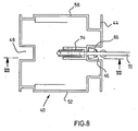
- a hollow support 10 which is made of sheet steel and has a cross section of about 90 x 90 mm in the support area.
- the hollow support 10 has at its lower end a base plate 12 which is firmly connected to it, preferably welded to it, with dimensions of approx. 380 x 180 x 15 mm, which is provided with four screw holes 14, by means of which the base plate is doweled with the base can.
- Two threaded holes 16 are used to receive an adjusting screw 18 with a lock nut.
- 1 and 2 are preferably arranged in the third points of the 9.75.m long side wall of a squash field, optionally also in the game wall at various spaced-apart locations, and there firmly with the hollow supports 10 or loader U-profiles spaced plastic-coated chipboard 20, 22 connected, preferably glued, which makes it possible to align and stiffen the wall in question both horizontally and vertically without affecting the critical rebound properties of the wall in a negative way would.
- Fig. 3 shows two abutting squash playing fields with playing areas 24 and 26.
- a play wall generally designated 28
- side wall 30 is located on the front side of the two playing areas 24, 26.
- the playing surface 26 shown at the top in FIG. 3 is delimited on its side facing away from the playing wall 28 by an input wall 32, while a glass wall 34 is located at the corresponding point on the playing surface 24.
- the game walls 28, the side wall 30 and the input wall 32 are each constructed in the manner known in principle from DE-OS 27 31 484 from particle boards 20, 22, which are made of aluminum or steel by U-profiles 36 serving as vertical wall closures, furthermore kept at a distance by vertical profiles, preferably I-profiles made of aluminum, which are arranged at a distance in the plate interspace 38 and are spaced apart.
- the pressboard 20, 22 consist of highly compressed material with a comparatively large proportion of phenolic resin, the large-area pressboard forming the walls of the squash field being constructed from individual plates which are seamlessly bonded to one another on the spot.
- the pressboard 20, 22 are coated at the factory with a two-component polyurethane system with flame-retardant additives as a primer, which cause flame resistance.
- the coating system is a low-solvent coating system, with a double primer with the material available under the trade name Pefalon 115 Primer FH preferably being used as the coating at the factory.
- abutting chipboards are then glued together seamlessly horizontally, but possibly also vertically, whereby the two-component material available under the trade name COMPAKTA PU adhesive VP 621-007, for example, can be used directly on the glue points when assembling.
- the adhesive is strongly pressed together during the horizontal bonding, whereby the excess material is pressed out laterally. After drying for about 1 to 2 days, the excess material is repelled, whereupon the surface is coated with a synthetic resin spatula, for example one under the trade name Metall-Spachtel SCHRAMM 616/83/7500 GFS 022 available two-component filler can be used.
- a synthetic resin spatula for example one under the trade name Metall-Spachtel SCHRAMM 616/83/7500 GFS 022 available two-component filler can be used.
- a top coating by means of a two-component water-based paint system with highly abrasion-resistant paint resins based on epoxy resin, also with flame-retardant additives, preferably a material available under the trade name Pefalon-XL top coating can be used.
- This final coating is precisely adapted to the needs of the squash game both in its color and in the degree of roughness, preferably by adding sand according to the
- the space between the plates 38 is filled with annealed, i.e. fire-dried quartz sand with a grain size of 1-3 mm, the smaller the grain size, the smaller the grain, the smaller the momentum that returns the ball to the playing field after hitting one of the walls.
- annealed i.e. fire-dried quartz sand with a grain size of 1-3 mm
- Fig. 3 also shows a serving as a vertical wall closure and for connecting adjoining walls, in the embodiment shown the side wall 30 and the input wall 32 and the glass wall 34, hollow support profile 40, which has a substantially square basic cross section in horizontal section.
- Two mutually opposite side surfaces 42, 44 of the support profile 40 have external central longitudinal grooves 46, 48 which run symmetrically to the longitudinal axis of the profile and which are arranged to accommodate wall attachments (e.g., as arranged above the actual walls 28, 30, 32, 34 to be described) 50 shown in Fig. 9) serve.
- the two essentially flat side surfaces 52, 54 arranged perpendicular to the side surfaces 42, 44 of the support profile 40 are essentially continuous, so that here, as in the rest of the case, also in the manner shown in FIG. 3, on the side surfaces 44, 42 , vertical U-profiles 36 serving to close the wall, in particular can be screwed on, but in each case a corner shoulder 56, 58 is provided in the edge area of the side surfaces 62, 54 facing the side surface 44, which is intended for receiving a glass wall 34 or the like, but can also serve to receive the protruding longitudinal edge region of pressboard plates 20, 22 over the U-profile 36, as shown in FIG. 3 at the top right for the case of the corner heel 58 and the pressboard plate 20.
- the support profiles 40 which are preferably made of aluminum, are installed, for example, in the manner shown in FIG. 3 on the rear of the side walls 30, i.e. thus they are located in the transition area from side wall 30 and rear wall 32 or 34.
- the support profiles 40 can have both glass panes 34 and normal playing field walls, for example 30 or 32, and also wall attachments 50 (FIG. 9) in their corresponding form vertical vertical grooves 46, 38 or corner shoulders 56, 58 or recesses 60, 62 or connected to the corresponding U-profiles 36, in particular screwed.
- FIG. 4 shows a side view of a side wall 30 of the type already described, the upper edge of which from the game wall 28 (shown on the right in FIG. 4) to the entrance wall 32 (shown on the left in FIG. 4) slopes obliquely in the manner customary for squash courts runs below.
- a profiled section 64 is provided as the upper end of the side wall 30, the details of which are described in detail below with reference to FIG. 9.
- An identical profile 64 also runs along the upper edge of the game wall 26, the details "A", "B” and “C” of FIG. 4 being explained and described in more detail below.
- FIG. 5 and 6 show the detail "A" of FIG. 4.
- the support profile 40 there has on its side facing the side wall 30 of FIG. 4 in the central longitudinal groove 46 a curtain rail-like fastening device 66 which 4 by means of hook elements 68, the side catch 44 in this exemplary embodiment are provided in the manner of a flange over the corner tabs ---. + 2e 58 and 56 in the manner which is further evident from the drawing, whereby the Corner shoulders 56, 58 are formed into longitudinal grooves.
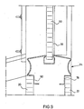
- FIG. 9 shows the cut-out profile 64 shown schematically there with the wall attachment 50 already mentioned in section.
- the details of the profile 64 which serves as a horizontal wall finish and Which, essentially U-shaped, engages with its legs 78, 80 between the chipboard 20, 22 at its upper edge, are explained in detail below with reference to FIG. 10.
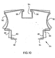
- the profiled section 64 shown in FIG. 10, as already stated, has a substantially U-shaped basic cross section, is made from resilient steel sheet with a thickness of approximately 1.25 mm.
- the legs 80, 82 are essentially bent at right angles at the end.
- a substantially rectangular corner recess 86, 88 is provided in connection with the corner flanges 82, 84 thus formed.
- a concave outline 90, 92 adjoins the corner recesses 86, 87 on both sides of the profile.
- the profile 64 On its web side, the profile 64 has an external, central longitudinal groove 94 into which the web of the U-profile merges with the formation of two internal longitudinal grooves 96, 98 with an essentially rectangular cross section.
- the profiled section 64 is used in such a way that the legs 80, 82 are brought from the position shown in broken lines in FIG. 10 by bending together into the position shown in solid lines and in this way are introduced into the plate space between pressboard plates 20, 22, whereby 9, the edge sections of the plates are then seated in the corner recesses 86, 88 in the manner shown in FIG. 9, the profiled section reliably remaining in the edge region of the space between the plates due to the resilient effect of the steel plate used.
- the longitudinal groove 94 can be used for receiving a wall attachment 50 or the like, as can also be seen in FIG. 9.
- the concave lines 90, 92 ensure reliable jumping of the ball and thus immediate recognition of a ball that is no longer valid, the walls of the squash court being optimally stiffened by the introduction of the profile 64.
- the entire profile 64 is preferably dashed in red, so that the lines 90, 92 are clearly visible.
Landscapes
- Engineering & Computer Science (AREA)
- Architecture (AREA)
- Civil Engineering (AREA)
- Structural Engineering (AREA)
- Finishing Walls (AREA)
- Pinball Game Machines (AREA)
- Laminated Bodies (AREA)
- Floor Finish (AREA)
- Building Environments (AREA)
Abstract
Description
Die Erfindung betrifft ein Squash-Spielfeld, bestehend aus einer Bodenplatte und vier Wänden, die aus durch Stützen auf Abstand gehaltenen kunststoffbeschichteten Preßspanplatten und einem Plattenzwischenraum bestehen, der durch eine Sandfüllung ausgefüllt ist.The invention relates to a squash court, consisting of a base plate and four walls, which consist of spaced plastic-coated chipboard by means of supports and a plate space which is filled with a sand filling.
Das Squash-Ballspiel erfreut sich auch in Europa zunehmender Beliebtheit. Das Spielfeld besteht aus einem rechteckigen Hof mit einer Länge von 9.75 m und einer Breite von 6,40 m. Die Basis des Spielfeldes ist ein Holzschwingboden, vorzugsweise aus Buchenriemen. Die Höhe des Spielfeldes beträgt an einer der beiden kürzeren Stirnwände 4,57 m und an der gegenüberliegenden anderen Stirnwand 2,13 m. Die obere Begrenzung des Spielfeldes ist durch einen 5 cm breiten Streifen, vorzugsweise roten Streifen, gekennzeichnet. Dieser Streifen ist bei einem in einer Halle aufstellbaren.Hof zugleich die obere Begrenzung der Seitenwände. Ein solcher Hof muß in einem überdachten Raum aufgestellt werden, dessen Höhe einen freien Spielraum vom Boden bis zur Decke von 6 m ermöglicht. Bei einem Freilandhof werden Wände mit einer allseitigen Höhe von mindestens 6 m benötigt.The squash ball game is also becoming increasingly popular in Europe. The playing field consists of a rectangular courtyard with a length of 9.75 m and a width of 6.40 m. The base of the playing field is a wooden swing floor, preferably made of beech straps. The height of the playing field is 4.57 m on one of the two shorter end walls and 2.13 m on the other end wall opposite. The upper boundary of the playing field is marked by a 5 cm wide stripe, preferably a red stripe. This strip can be used in a hall that can be set up in a hall, and at the same time the upper boundary of the side walls. Such a courtyard must be set up in a roofed room, the height of which allows free play from the floor to the ceiling of 6 m. For an open-air yard, walls with an all-round height of at least 6 m are required.
Das Squash-Ballspiel wird zu zweit mit einem Ball gespielt, der beim Aufprall oder beim Schlag den ihm erteilten Impuls teilweise in Verformungsarbeit umsetzt, der also nicht voll elastisch ist. Dieser Ball wird abwechselnd von beiden Spielern an irgendeine der vier Hofwände geschlagen und muß jeweils zwischen zwei aufeinanderfolgenden Schlägen der beiden Spieler die größere Stirnwand berührt haben.The squash ball game is played in pairs with a ball that partially converts the impulse given to it into impact work when it strikes or strikes, so it is not fully elastic. This ball is alternately struck by either player on any of the four courtyard walls and must have touched the larger front wall between two successive strikes by the two players.
Es war bisher weitestgehend üblich, die Wände von Squash-Spielfeldern in Stahlbeton zu gießen. Dies wurde auch als unbedingt erforderlich erachtet, da man bisher der Ansicht war, daß im wesentlichen nur Betonwände geeignet sind, den Ball in der für das Squash-Spiel geeigneten Weise abprallen zu lassen, wobei auch die Oberfläche von Beton geeignet ist, dem Ball den für das Spiel entsprechenden Drall zu verleihen. Squash-Spielfelder mit Betonwänden haftet jedoch der Nachteil an, daß sie in der Herstellung benötigen und darüber hinaus ohne Zerstörung nicht mehr von der Stelle zu bewegen sind. Außerdem müssen die Wände von Squash-Spielfeldern vollständig plan und senkrecht angeordnet sein und darüber hinaus in genauen Abständen parallel zueinander verlaufen. Die erforderliche Maßgenauigkeit läßt bei den oben angegebenen Abmessungen nur Toleranzen bis zu 2 mm zu. Eine solche Maßgenauigkeit ist mit betonierten Wänden nur sehr schwer und mit einem sehr großen Aufwand zu erreichen. Schließlich ist es auch technisch schwierig, diese Wände fugenlos herzustellen. Insbesondere ist es schwierig, die Abdrücke von Fugenbändern, welche die Schalungsfugen verschließen, zu vermeiden, bzw. nachträglich zu beseitigen.So far, it has been largely customary to pour the walls of squash courts in reinforced concrete. This was also considered to be absolutely necessary since it was previously thought that essentially only concrete walls are suitable for bouncing the ball in the manner suitable for the squash game, the surface of concrete also being suitable for the ball to give appropriate twist for the game. Squash courts with concrete walls, however, have the disadvantage that they need to be manufactured and, moreover, cannot be moved without being destroyed. In addition, the walls of squash courts must be completely flat and vertical, and must also run parallel to one another at precise intervals. The required dimensional accuracy only allows tolerances of up to 2 mm for the dimensions given above. Such dimensional accuracy is very difficult to achieve with great effort and with concrete walls. After all, it is also technically difficult to make these walls seamless. In particular, it is difficult to avoid the imprints of joint tapes that close the formwork joints or to remove them later.
Aus der GB-A- 14 29 635 ist bereits ein Squash-Spielfeld, bestehend aus einer Bodenplatte und vier Wänden, die aus durch Streben aui Abstand gehaltenen Platten und einem im Pfattenzwischenraum befindlichen Füllmaterial bestehen, bekannt, bei dem die Wände aus durch Streben auf gegenseitigem Abstand gehaltenen Asbestzementplatten bestehen, in denen Plattenzwischenraum bis zu einer bestimmten Füllhöhe Beton eingefüllt ist: Derartigen Squash-Spielfeldern haften im wesentlichen ebenfalls die weiter oben bereits aufgeführten Nachteile an, die generell mit der Verwendung von Beton verbunden sind, wobei die Wände insbesondere auch nicht über hinreichend gute und definierte Rückpralleigenschaften verfügen. Nachteilig ist bei diesem Squash-Spielfeld insbesondere, daß dort die Wandplatten, aus Asbestelement bestehend, durch ver-hältnismäßig massive Balkenkonstruktion auf Abstand gehalten sind, wodurch keine optimalen Rückpralleigenschaften der Wände erzielt werden können, da die durch die jeweiligen Streben erfaßten Wandbereiche hinsichtlich ihrer Rückpralleigenschaften elastisch "tot" sind.From GB-A-14 29 635 a squash court is already known, consisting of a base plate and four walls, which consist of plates spaced apart by struts and a filling material located in the space between the plates, in which the walls are made of struts Mutually spaced asbestos cement plates exist, in which the space between the plates is filled up to a certain filling level: squash courts of this type also essentially have the disadvantages already mentioned above, which are generally associated with the use of concrete, the walls in particular not have sufficiently good and defined rebound properties. A disadvantage of this squash court is that the wall panels, made of asbestos elements, are kept at a distance by relatively solid beam construction, which means that optimal rebound properties of the walls cannot be achieved, since the rebound properties of the wall areas captured by the respective struts are elastically "dead".
Zur Lösung der Aufgabe, mit relativ geringem Aufwand ein maßgenaues, leicht zu errichtendes Squash-Spielfeld mit optimalen Rückpralleigenschaften zu schaffen, ist in der DE-A- 27 31 484 ein Squash-Spielfeld der eingangs genannten Art beschrieben, bei dem die Spanplatten mittels I-Profilen gehaltert sind, deren Flansch-Außenseiten mit den Innenseiten der Spanplatten fest verbunden, vorzugsweise verklebt sind. Die I-Profile bestehen dabei vorzugsweise aus Aluminium und können auch die Last der Dachkonstruktion aufnehmen.To solve the task of creating a dimensionally accurate, easy-to-erect squash field with optimal rebound properties with relatively little effort, a squash field of the type mentioned is described in DE-A-27 31 484, in which the chipboard by means of I Profiles are held, the flange outer sides of which are firmly connected, preferably glued, to the inner sides of the chipboard. The I-profiles are preferably made of aluminum and can also bear the load of the roof structure.
Das bekannte Squash-Spielfeld der vorstehend beschriebenen Art hat sich im Prinzip durchaus bewährt, jedoch hat es sich gezeigt, daß hinsichtlich der genaueren Einstellbarkeit der Rückpralleigenschaften der Spielfeldwände sowie der genauen Justierbarkeit sowie leichten Montagen derselben, insgesamt hinsichtlich der Spieleigenschaften, wie zuverlässiges "Disqualifizieren" von "Aus-Bällen" etc., noch weitere Verbesserungen wünschenswert sind.The known squash field of the type described above has proven itself in principle, but it has been shown that with regard to the more precise adjustability of the rebound properties of the field walls and the exact adjustability and easy assembly thereof, overall with regard to the playing characteristics, such as reliable "disqualification" of "balls" etc., further improvements are desirable.
Der Erfindung liegt daher die Aufgabe zugrunde, das gattungsgemäße Squash-Spielfeld dahingehend zu verbessern, daß insgesamt optimierte Spieleigenschaften erzielt und insbesondere die Steifigkeit und Montierbarkeit der Spielfeldwände günstiger gestaltet wird.The invention is therefore based on the object of improving the generic squash field in such a way that overall optimized playing properties are achieved and in particular the rigidity and mountability of the field walls is made more favorable.
Erfindungsgemäß wird diese Aufgabe bei einem Squash-Spielfeld der gattungsgemäßen Art dadurch gelöst, daß die zwischen den Preßspanplatten angeordnete Sandfüllung aus feuergetrocknetem Quarzsand mit einer Körnung von 1 - 3 mm besteht; und daß die vorgefertigten Preßspanplatten mit einer ersten, werksseitig aufgebrachten Grundierung aus einem lösungsmittelarmen Zweikomponenten-Polyurethansystem mit schwer entflammbaren Zusätzen und einer am Aufstellungsort aufgebrachten Deckbeschichtung aus einem hochabriebbeständigen Lackharzsystem auf wässriger Epoxidharzbasis beschichtet sind.According to the invention, this object is achieved in a squash field of the generic type in that the sand filling arranged between the particle boards consists of fire-dried quartz sand with a grain size of 1-3 mm; and that the prefabricated chipboard with a first, factory-applied primer made of a low-solvent two-component polyurethane system with flame retardant additives and a top coating applied at the installation site from one highly abrasion-resistant paint resin system coated with an aqueous epoxy resin.
Es hat sich herausgestellt, daß feuergetrockneter Quarzsand der beanspruchten Körnung besonders günstige Rückpralleigenschaften ergibt. Die erfindungsgemäß vorgesehene Beschichtung der Preßspanplatten gewährleistet in Verbindung mit der beanspruchten Art der Sandfüllung optimale Spieleigenschaften.It has been found that fire-dried quartz sand of the claimed grain gives particularly favorable rebound properties. The coating of the particle board provided according to the invention, in conjunction with the claimed type of sand filling, ensures optimum playing properties.
Besonders bevorzugte Ausführungsformen der Erfindung sind Gegenstand der Unteransprüche.Particularly preferred embodiments of the invention are the subject of the dependent claims.
Nachstehend sind Ausführungsbeispiele der Erfindung anhand der Zeichnung im einzelnen erläutert. Dabei zeigt:
- Fig. 1 eine bei einem Squash-Spielfeld nach der Erfindung verwendete Hohlstütze mit Bodenplatte in der Draufsicht;
- Fig. 2 einen Schnitt entlang der Linie 11-11 von Fig. 1;
- Fig. 3 fünf aneinanderstoßende Wände zweier Squash-Spielfelder nach der Erfindung in der Draufsicht;
- Fig. 4 eine Seitenwand eines Squash-Spielfeldes in der Seitenansicht, teilweise geschnitten;
- Fig. 5 das Detail "A" von Fig. 4 im vertikalen Schnitt parallel zur Zeichenebene von Fig. 4, zugleich als Schnittdarstellung entsprechend.der Linie V-V von Fig.6, in Richtung der Pfeile gesehen;
- Fig. 6 eine Schnittdarstellung entlang der Linie VI-VI von Fig. 5, in Richtung der Pfeile gesehen;
- Fig. 7 das Detail "B" von Fig. 4 im vertikalen Schnitt parallel zur Zeichenebene von Fig. 4, zugleich als Schnittdarstellung entsprechend der Linie VII-VII von Fig. 8, in Richtung der Pfeile gesehen;
- Fig. 8 das Detail "B" von Fig. 4 bzw. 7 in der Draufsicht;
- Fig. 9 das Detail "C" von Fig. 4 im Schnitt parallel zur Zeichenebene von Fig. 4; und
- Fig. 10 das in Fig. 9 wiedergegebene Ausprofil eines Squash-Spielfeldes nach der Erfindung im Schnitt senkrecht zur Längserstreckung des Ausprofiles, wie in Fig. 9.
- Figure 1 is a hollow support with a base plate used in a squash court according to the invention in plan view.
- FIG. 2 shows a section along the line 11-11 of FIG. 1;
- Figure 3 shows five abutting walls of two squash courts according to the invention in plan view.
- 4 shows a side wall of a squash court in a side view, partially in section;
- Fig. 5 shows the detail "A" of Fig. 4 in vertical section parallel to the plane of Fig. 4, at the same time as a sectional view corresponding to the line VV of Fig. 6, seen in the direction of the arrows;
- Figure 6 is a sectional view taken along the line VI-VI of Figure 5, in the direction of the arrows.
- 7 shows the detail "B" from FIG. 4 in a vertical section parallel to the plane of FIG. 4, at the same time as a sectional view along the line VII-VII from FIG. 8, seen in the direction of the arrows;
- Fig. 8 shows the detail "B" of Figures 4 and 7 in plan view.
- FIG. 9 shows the detail "C" from FIG. 4 in a section parallel to the drawing plane from FIG. 4; and
- 10 shows the profile of a squash field according to the invention shown in FIG. 9 in section perpendicular to the longitudinal extent of the profile, as in FIG. 9.
In Fig. 1 und 2 der Zeichnung ist eine Hohlstütze 10 gezeigt, die aus Stahlblech hergestellt ist und im Stützenbereich einen Querschnitt von ca. 90 x 90 mm hat. Die Hohlstütze 10 weist an ihrem unteren Ende eine fest mit ihr verbundene, vorzugsweise mit ihr verschweißte Bodenplatte 12 mit Abmessungen von ca. 380 x 180 x 15 mm auf, welche mit vier Schraublöchern 14 versehen ist, mittels welcher die Bodenplatte mit der Unterlage verdübelt werden kann. Zwei Gewindebohrungen 16 dienen zum Aufnehmen je einer Justierschraube 18 mit Kontermutter. Hohlstützen der in Fig. 1 und 2 beschriebenen Art sind vorzugsweise jeweils in den Drittelpunkten der 9,75.m langen Seitenwand eines Squash-Spielfeldes, gegebenenfalls zusätzlich auch in der Spielwand an verschiedenen auf Abstand stehenden Stellen, angeordnet und dort fest mit durch die Hohlstützen 10 bzw. lader U-Profile auf Abstand gehaltenen kunststoffbeschichteten Preßspanplatten 20, 22 verbunden, vorzugsweise verklebt, wodurch es möglich ist, die betreffende Wand einwandfrei sowohl horizontal als auch vertikal auszurichten und zu versteifen, ohne daß die kritischen Rückpralleigenschaften der Wand in negativer Weise beeinflußt würden.1 and 2 of the drawing, a
Fig. 3 zeigt zwei aneinanderstoßende Squash-Spielfelder mit Spielflächen 24 bzw. 26. An der Stirnseite der beiden Spielflächen 24, 26 ist jeweils eine im Ganzen mit 28 bezeichnete Spielwand angeordnet, während sich zwischen den beiden Spielflächen 24, 26 eine senkrecht zur Spielwand 28 verlaufende Seitenwand 30 befindet. Die in Fig. 3 oben gezeigte Spielfläche 26 ist an ihrer der Spielwand 28 abgewandten Seite durch eine Eingangswand 32 begrenzt, während sich an der entsprechenden Stelle bei der Spielfläche 24 eine Glaswand 34 befindet. Die Spielwände 28, die Seitenwand 30 und die Eingangswand 32 sind jeweils in der im Prinzip aus der DE-OS 27 31 484 bekannten Weise aus Preßspanplatten 20, 22 aufgebaut, die durch als vertikale Wandabschlüsse dienende U-Profile 36 aus Aluminium oder Stahl bestehend, weiterhin durch nicht-gezeigte, im Plattenzwischenraum 38 mit Abstand angeordnete vertikale Profile, vorzugsweise I-Profile aus Aluminium, auf Abstand gehalten. Die Preßspanplatten 20, 22 bestehen bei dem Squash-Spielfeld nach der Erfindung aus hochverdichtetem Material mit verhältnismäßig großem Phenolharzanteil, wobei die die Wände des Squash-Spielfeldes bildenden großflächigen Preßspanplatten aus an Ort und Stelle fugenlos miteinander verklebten Einzelplatten aufgebaut sind. Werkseitig sind die Preßspanplatten 20, 22 mit einem Zweikomponenten Polyurethansystem mit schwer entflammbaren Zusätzen als Grundierung beschichtet, die eine Flammwidrigkeit hervorrufen. Das Beschichtungssystem stellt ein lösungsmittelarmes Lacksystem dar, wobei als Beschichtung vorzugsweise werkseitig eine zweifache Grundierung mit dem unter dem Handelsnamen Pefalon 115 Grundierung FH erhältliches Material verwendet wird. Beim Aufbau des Squash-Spielfeldes werden aneinanderstoßende Preßspanplatten dann horizontal, gegebenenfalls aber auch vertikal, fugenlos miteinander verklebt, wobei als Kleber beim Zusammensetzen unmittelbar auf den Klebestellen beispielsweise das unter dem Handelsnamen COMPAKTA PU-Kleber VP 621-007 erhältliche Zweikomponentenmaterial verwendet werden kann. Durch das Gewicht der oberen, aufzusetzenden und einzufügenden Preßspanplatte wird bei der horizontalen Verklebung der Kleber stark zusammengepreßt, wobei das überschüssige Material seitlich herausgedrückt wird. Nach einem Abtrocknen von ungefähr 1 bis 2 Tagen wird das überstehende Material abgestoßen, woraufhin die Fläche mit einem Kunstharzspachtel, beispielsweise eines unter dem Handelsnamen Metall-Spachtel SCHRAMM 616/83/7500 GFS 022 erhältlicher Zweikomponentenspachtel verwendet werden kann. Im Anschluß hieran erfolgt eine Deckbeschichtung mittels eines Zweikomponenten-Farbsystems auf wäßriger Basis mit hochabriebbeständigen Lackharzen auf Epoxidharzgrundlage, ebenfalls mit flammhemmenden Zusätzen, wobei vorzugsweise ein unter dem Handelsnamen Pefalon-XL-Deckbeschichtung erhältliches Material verwendet werden kann. Diese Endbeschichtung ist sowohl in ihrer Farbe als auch im Rauhigkeitsgrad, vorzugsweise durch Sandzusatz nach der Lehre der DE-OS 27 31 484, den Bedürfnissen des Squash-Spieles genau angepaßt, wobei die Farbe vorzugsweise ein gelbgrau getöntes Weiß ist.Fig. 3 shows two abutting squash playing fields with
Der Plattenzwischenraum 38 ist mit ausgeglühtem, also feuergetrocknetem Quarzsand mit einer Körnung von 1 - 3 mm gefüllt, wobei der Impuls, der den Ball nach dem Auftreffen auf eine der Wände in das Spielfeld zurückbringt, um so kleiner ist, je kleiner die Körnung ist. Hierdurch läßt sich ein Spielfeld also entweder entsprechend "schnell" oder entsprechend "langsam" einstellen, je nach den klimatischen Verhältnissen etc. da der gasgefüllte Squash-Ball in Ländern mit verhältnismäßig heißem Klima besonders schnell ist, während andererseits in kälteren Klimazonen eingerichtete Anlagen verhältnismäßig schnell eingestellt werden müssen, wegen der dort geringeren Rückprallwirkung auf den gasgefüllten Ball bzw. dessen "weicherer" Elastizität.The space between the
Fig. 3 läßt weiterhin ein als vertikaler Wandabschluß sowie zum Verbinden aneinanderstoßender Wände, bei dem gezeigten Ausführungsbeispiel der Seitenwand 30 und der Eingangswand 32 sowie der Glaswand 34, dienendes hohles Stützprofil 40 erkennen, welches im horizontalen Schnitt im wesentlichen quadratischen Grundquerschnitt hat. Zwei einander gegenüberliegende Seitenflächen 42, 44 des Stützprofiles 40 weisen im wesenhlichen symmetrisch zur Profillängsachse verlaufende außenliegende Mittel-Längsnuten 46, 48 auf, die zum Aufnehmen von oberhalb der eigentlichen Wände 28, 30, 32, 34 angeordneten, noch zu beschreibenden Wandaufsätzen (z.B. als 50 in Fig. 9 gezeigt)dienen. Weiterhin sind die beiden senkrecht zu den Seitenflächen 42, 44 des Stützprofiles 40 angeordneten im wesentlichen ebeneh Seitenflächen 52, 54 im wesentlichen durchgehend ausgebildet, so daß hier, wie im übrigen aber auch in der aus Fig. 3 ersichtlichen Weise an den Seitenflächen 44, 42, vertikale, dem Wandabschluß dienende U-Profile 36 befestigt, insbesondere angeschraubt werden können, wobei jedoch in dem der Seitenfläche 44 zugewandten Randbereich der Seitenflächen, 62, 54 jeweils ein Eckabsatz 56, 58 vorgesehen ist, der zum Aufnehmen einer Glaswand 34 oder dergleichen, aber auch zum Aufnehmen des über das U-Profil 36 vorspringenden Längskantenbereiches von Preßspanplatten 20, 22 dienen kann, wie dies in Fig. 3 rechts oben für den Fall des Eckabsatzes 58 und die Preßspan-platte 20 gezeigt ist. An der den Eckabsätzen 56, 58 abgewandten Längskante der Seitenflächen 52, 54 sind Vertiefungen 60, 62 vorgesehen, die ebenfalls zum Aufnehmen überstehender Randbereiche der dort jeweils anzuordnenden Preßspanplatten 22 bzw. 20 dienen. Die Stützprofile 40, die vorzugsweise aus Aluminium hergestellt sind, werden beispielsweise in der aus Fig. 3 ersichtlichen Weise an der Rückseite der Seitenwände 30 eingebaut, d.h. also sie befinden sich im Übergangsbereich von Seitenwand 30 und Rückwand 32 bzw. 34. Infolge der beschriebenen Form können die Stützprofile 40 sowohl Glasscheiben 34 als auch normale Spielfeldwände, beispielsweise 30 bzw. 32, und auch Wandaufsätze 50 (Fig. 9) in ihren entsprechenden vertikalen Längsnuten 46, 38 bzw. Eckabsätzen 56, 58 bzw. Vertiefungen 60, 62 aufnehmen oder mit den entsprechenden U-Profilen 36 verbunden, insbesondere verschraubt werden.Fig. 3 also shows a serving as a vertical wall closure and for connecting adjoining walls, in the embodiment shown the
Fig. 4 zeigt in der Seitenansicht eine Seitenwand 30 der bereits beschriebenen Art, deren Oberkante von der Spielwand 28 (in Fig. 4 rechts gezeigt) zur Eingangswand 32 (in Fig. 4 links gezeigt) in der für Squash-Spielfelder üblichen Weise schräg nach unten verläuft. Als oberer Abschluß der Seitenwand 30 ist ein Ausprofil 64 vorgesehen, dessen Einzelheiten weiter unten noch unter Bezugnahme auf Fig. 9 ausführlich beschrieben werden. Ein identisches Ausprofil 64 verläuft auch entlang der Oberkante der Spielwand 26, wobei die Details "A", "B" und "C" von Fig. 4 nachstehend noch näher erläutert und beschrieben sind.FIG. 4 shows a side view of a
Fig. 5 und 6-zeigen das Detail "A" von Fig. 4. Wie hieraus hervorgeht, weist das Stützprofil 40 dort an seiner der Seitenwand 30 von Fig. 4 zugewandten Seite in der Mittel-Längsnut 46 eine vorhangschienenartige Befestigungseinrichtung 66 auf, welche mittels Hakenelementen 68 ein in Fig. 4 gezeigtes Ballfangnetz 70 haltern, wobei die Seitenfläche 44 bei diesem Ausführungsbeispiel über die Eckabs---.+2e 58 bzw. 56 in der aus der Zeichnung ohn.- weiteres ersichtlichen Weise flanschartig vorgesehen sind, wodurch die Eckabsätze 56, 58 zu Längsnuten umgebildet sind.5 and 6 show the detail "A" of FIG. 4. As can be seen from this, the
Hinsichtlich des Details "B" von Fig. 4 geht aus den Fig. 7 und 8 hervor, daß das Ballfangnetz 70 von Fig. 4, welches oberhalb der Seitenwand 30 angeordnet ist, über ein Spannseil 72 dauernd unter Spannung gehalten ist, welches über eine Umlenkrolle 74 läuft, die nahe dem oberen Ende des Stützprofiles 40 innerhalb des inneren Hohlraumes desselben angeordnet ist, wobei am unteren Ende des Spannseiles 72 ein Gewicht 76 hängt. Hierdurch ist auf raumsparende, ästhetisch ansprechende Weise ein stetes Straffhalten des Ballfangnetzes gewährleistet.With regard to the detail "B" of FIG. 4, it is apparent from FIGS. 7 and 8 that the
Hinsichtlich Detail "C" von Fig. 4 zeigt Fig. 9 das dort schematisch wiedergegebene Ausprofil 64 mit dem bereits erwähnten Wandaufsatz 50 im Schnitt. Die Einzelheiten des Ausprofils 64, welches als horizontaler Wandabschluß dient und welches, im wesentlichen U-förmig ausgebildet, mit seinen Schenkeln 78, 80 zwischen die Preßspanplatten 20, 22 an deren oberem Rand eingreift, werden nachfolgend anhand von Fig. 10 im einzelnen erläutert.With regard to detail "C" from FIG. 4, FIG. 9 shows the cut-
Das in Fig. 10 gezeigte Ausprofil 64 mit, wie bereits ausgeführt, im wesentlichen U-förmigem Grundquerschnitt, ist aus federndem Stahlblech mit einef Stärke von ca. 1,25 mm hergestellt. Die Schenkel 80, 82 sind am Ende nach innen im wesentlichen rechtwinklig abgeknickt. In Anschluß an die so gebildeten Eckflansche 82, 84 ist jeweils ein im wesentlichen rechtwinkliger Eckrücksprung 86, 88 vorgesehen. An die Eckrücksprünge 86, 87 schließt auf beiden Seiten des Ausprofiles jeweils eine konkave Auslinie 90, 92 an. An seiner Stegseite weist das Ausprofil 64 eine außenliegende, mittige Längsnut 94 auf, in welche der.Steg des U-Profiles unter Bildung zweier innenliegender Längsnuten 96, 98 mit im wesentlichen rechteckigem Querschnitt übergeht.The profiled
Das Ausprofil 64 wird in der Weise verwendet, daß die Schenkel 80, 82 aus der in Fig. 10 gestrichelt wiedergegebenen Position unter Zusammenbiegen in die in ausgezogenen Linien wiedergegebene Position gebracht und auf diese Weise in den Plattenzwischenraum zwischen Preßspanplatten 20, 22 eingebracht werden, wobei also die Randabschnitte der Platten dann anschließend in der in Fig. 9 gezeigten Weise in den Eckrücksprüngen 86, 88 sitzen, wobei das Ausprofil durch die rückfedernde Wirkung des verwendeten Stahlbleches zuverlässig im Randbereich des Plattenzwischenraumes sitzenbleibt. Die Längsnut 94 kann zur Aufnahme eines Wandaufsatzes 50 o. dgl. verwedet werden, wie dies ebenfalls in Fig. 9 erkennbar ist. Die konkaven Auslinien 90, 92 gewährleisten ein zuverlässiges Verspringen des Balles und damit ein sofortiges Erkennen eines nicht mehr gültigen Balles, wobei durch das Einbringen des Ausprofiles 64 die Wände des Squash-Spielfeldes im übrigen optimal versteift werden. Das gesamte Ausprofil 64 ist vorzugsweise in roter Farbe gestrichelt, so daß die Auslinien 90, 92 optisch gut erkennbar sind.The profiled
Claims (21)
Priority Applications (1)
| Application Number | Priority Date | Filing Date | Title |
|---|---|---|---|
| AT82103828T ATE18275T1 (en) | 1981-10-28 | 1982-05-05 | SQUASH COURT WITH WALLS FORMED BY PLASTIC-COATED CHIPBOARDS. |
Applications Claiming Priority (2)
| Application Number | Priority Date | Filing Date | Title |
|---|---|---|---|
| DE3142809A DE3142809C2 (en) | 1981-10-28 | 1981-10-28 | Squash playing field with walls formed by plastic-coated chipboard |
| DE3142809 | 1981-10-28 |
Publications (2)
| Publication Number | Publication Date |
|---|---|
| EP0077875A1 EP0077875A1 (en) | 1983-05-04 |
| EP0077875B1 true EP0077875B1 (en) | 1986-02-26 |
Family
ID=6145055
Family Applications (1)
| Application Number | Title | Priority Date | Filing Date |
|---|---|---|---|
| EP82103828A Expired EP0077875B1 (en) | 1981-10-28 | 1982-05-05 | Squash court with walls made of pressboard panels coated with plastics |
Country Status (3)
| Country | Link |
|---|---|
| EP (1) | EP0077875B1 (en) |
| AT (1) | ATE18275T1 (en) |
| DE (2) | DE3142809C2 (en) |
Families Citing this family (4)
| Publication number | Priority date | Publication date | Assignee | Title |
|---|---|---|---|---|
| DE3228279A1 (en) * | 1982-07-29 | 1984-02-02 | Squash Court Service GmbH, 2100 Hamburg | Device for the colour marking of a line on a wall of a squash court by means of a strip to be attached to the wall |
| JPS6055977A (en) * | 1983-09-02 | 1985-04-01 | ホルスト バビンスキー | Skash court having wall comprising plastic coated press board |
| DE3403848A1 (en) * | 1983-11-07 | 1985-08-14 | Horst 8225 Traunreut Babinsky | Wall structure and process for strengthening a boundary wall of a squash court |
| DE102010034733B4 (en) * | 2010-08-19 | 2019-05-16 | Horst Babinsky | Wall construction for a squash court and squash court |
Family Cites Families (5)
| Publication number | Priority date | Publication date | Assignee | Title |
|---|---|---|---|---|
| GB1429635A (en) * | 1972-03-17 | 1976-03-24 | Richardson D S | Squash court |
| US4068840A (en) * | 1976-08-09 | 1978-01-17 | Spaulding Jr Charles A | Playing surface for handball and racquetball courts |
| DE2731484C2 (en) * | 1977-07-12 | 1983-01-05 | Horst 8225 Traunreut Babinsky | Squash court |
| DE2844393A1 (en) * | 1978-10-12 | 1980-05-08 | Christian Warnick | Smooth squash court wall - has cladding vertically clamped and floating parallel to surface on support skeleton |
| DE2927910A1 (en) * | 1979-07-11 | 1981-01-29 | Ila Bau Gmbh & Co Kg | KIT FOR BUILDING A BUILDING WALL |
-
1981
- 1981-10-28 DE DE3142809A patent/DE3142809C2/en not_active Expired
-
1982
- 1982-05-05 DE DE8282103828T patent/DE3269311D1/en not_active Expired
- 1982-05-05 EP EP82103828A patent/EP0077875B1/en not_active Expired
- 1982-05-05 AT AT82103828T patent/ATE18275T1/en active
Also Published As
| Publication number | Publication date |
|---|---|
| DE3269311D1 (en) | 1986-04-03 |
| DE3142809A1 (en) | 1983-05-11 |
| DE3142809C2 (en) | 1985-06-05 |
| EP0077875A1 (en) | 1983-05-04 |
| ATE18275T1 (en) | 1986-03-15 |
Similar Documents
| Publication | Publication Date | Title |
|---|---|---|
| DE4226742A1 (en) | Cladding element for floors, ceilings, walls and facades | |
| DE2636531A1 (en) | Prefabricated hollow wall building panel - has disc extensions glued to panel inside and spacer bar ends | |
| EP0378725A1 (en) | Skate board tracks made from individual modules | |
| EP0077875B1 (en) | Squash court with walls made of pressboard panels coated with plastics | |
| DE3229262A1 (en) | Wooden structural element in the form of a panel | |
| DE3152991A1 (en) | Plastics coated chipboard panel walled squash court - has outside profile horizontally finishing sand-filled panel gaps with concave line | |
| DE2731484C2 (en) | Squash court | |
| DE8131541U1 (en) | Squash playing field with walls formed by plastic-coated chipboard | |
| DE3152993A1 (en) | Squash court with supporting structure for the walls | |
| WO1984001598A1 (en) | Separation device for door-case on different height floors | |
| AT15447U1 (en) | Back cork façade base plate and thermal insulation composite system with cork facade base plate | |
| DE3152992A1 (en) | Squash court with corner supports | |
| DE19738571B4 (en) | wall unit | |
| CH683443A5 (en) | Blockhouse-type building. | |
| DE4302006C2 (en) | Scaffold composite screed | |
| DE202019106901U1 (en) | Screen system for outdoors | |
| DE3225513A1 (en) | Panel-shaped building member having connection profile bars attached to the edges | |
| DE8708808U1 (en) | Sound absorbing and reflecting wall with wall cladding | |
| DE3520066C2 (en) | ||
| DE10218855B4 (en) | Plate-shaped component | |
| DE19522740C2 (en) | Device for protecting masonry of buildings against flooding | |
| DE3442759C2 (en) | ||
| DE3636874A1 (en) | Edge-guard profile, in particular stair nosing, and process for fastening it on a stair | |
| DE3504657C2 (en) | ||
| DE9115434U1 (en) | Children's playground kit for building play structures |
Legal Events
| Date | Code | Title | Description |
|---|---|---|---|
| PUAI | Public reference made under article 153(3) epc to a published international application that has entered the european phase |
Free format text: ORIGINAL CODE: 0009012 |
|
| AK | Designated contracting states |
Designated state(s): AT CH DE FR GB IT LI NL SE |
|
| 17P | Request for examination filed |
Effective date: 19831013 |
|
| GRAA | (expected) grant |
Free format text: ORIGINAL CODE: 0009210 |
|
| AK | Designated contracting states |
Designated state(s): AT CH DE FR GB IT LI NL SE |
|
| PG25 | Lapsed in a contracting state [announced via postgrant information from national office to epo] |
Ref country code: NL Effective date: 19860226 Ref country code: IT Free format text: LAPSE BECAUSE OF FAILURE TO SUBMIT A TRANSLATION OF THE DESCRIPTION OR TO PAY THE FEE WITHIN THE PRESCRIBED TIME-LIMIT;WARNING: LAPSES OF ITALIAN PATENTS WITH EFFECTIVE DATE BEFORE 2007 MAY HAVE OCCURRED AT ANY TIME BEFORE 2007. THE CORRECT EFFECTIVE DATE MAY BE DIFFERENT FROM THE ONE RECORDED. Effective date: 19860226 Ref country code: FR Free format text: THE PATENT HAS BEEN ANNULLED BY A DECISION OF A NATIONAL AUTHORITY Effective date: 19860226 |
|
| REF | Corresponds to: |
Ref document number: 18275 Country of ref document: AT Date of ref document: 19860315 Kind code of ref document: T |
|
| PG25 | Lapsed in a contracting state [announced via postgrant information from national office to epo] |
Ref country code: SE Effective date: 19860228 |
|
| REF | Corresponds to: |
Ref document number: 3269311 Country of ref document: DE Date of ref document: 19860403 |
|
| PGFP | Annual fee paid to national office [announced via postgrant information from national office to epo] |
Ref country code: AT Payment date: 19860521 Year of fee payment: 5 |
|
| NLV1 | Nl: lapsed or annulled due to failure to fulfill the requirements of art. 29p and 29m of the patents act | ||
| EN | Fr: translation not filed | ||
| PLBE | No opposition filed within time limit |
Free format text: ORIGINAL CODE: 0009261 |
|
| STAA | Information on the status of an ep patent application or granted ep patent |
Free format text: STATUS: NO OPPOSITION FILED WITHIN TIME LIMIT |
|
| 26N | No opposition filed | ||
| PG25 | Lapsed in a contracting state [announced via postgrant information from national office to epo] |
Ref country code: AT Effective date: 19870505 |
|
| PG25 | Lapsed in a contracting state [announced via postgrant information from national office to epo] |
Ref country code: LI Effective date: 19870531 Ref country code: CH Effective date: 19870531 |
|
| REG | Reference to a national code |
Ref country code: CH Ref legal event code: PL |
|
| PGFP | Annual fee paid to national office [announced via postgrant information from national office to epo] |
Ref country code: GB Payment date: 20010502 Year of fee payment: 20 |
|
| PGFP | Annual fee paid to national office [announced via postgrant information from national office to epo] |
Ref country code: DE Payment date: 20010531 Year of fee payment: 20 |
|
| REG | Reference to a national code |
Ref country code: GB Ref legal event code: IF02 |
|
| PG25 | Lapsed in a contracting state [announced via postgrant information from national office to epo] |
Ref country code: GB Free format text: LAPSE BECAUSE OF EXPIRATION OF PROTECTION Effective date: 20020504 |
|
| REG | Reference to a national code |
Ref country code: GB Ref legal event code: PE20 Effective date: 20020504 |