EP0077875B1 - Court de squash à parois constituées de panneaux de couches de matières plastiques pressées - Google Patents
Court de squash à parois constituées de panneaux de couches de matières plastiques pressées Download PDFInfo
- Publication number
- EP0077875B1 EP0077875B1 EP82103828A EP82103828A EP0077875B1 EP 0077875 B1 EP0077875 B1 EP 0077875B1 EP 82103828 A EP82103828 A EP 82103828A EP 82103828 A EP82103828 A EP 82103828A EP 0077875 B1 EP0077875 B1 EP 0077875B1
- Authority
- EP
- European Patent Office
- Prior art keywords
- squash court
- court according
- squash
- plates
- profile
- Prior art date
- Legal status (The legal status is an assumption and is not a legal conclusion. Google has not performed a legal analysis and makes no representation as to the accuracy of the status listed.)
- Expired
Links
- 235000009854 Cucurbita moschata Nutrition 0.000 title claims abstract description 51
- 235000009852 Cucurbita pepo Nutrition 0.000 title claims abstract description 51
- 235000020354 squash Nutrition 0.000 title claims abstract description 51
- 239000004033 plastic Substances 0.000 title claims abstract description 5
- 229920003023 plastic Polymers 0.000 title claims abstract description 5
- 240000001980 Cucurbita pepo Species 0.000 title claims abstract 23
- 239000011093 chipboard Substances 0.000 claims abstract description 19
- VYPSYNLAJGMNEJ-UHFFFAOYSA-N Silicium dioxide Chemical compound O=[Si]=O VYPSYNLAJGMNEJ-UHFFFAOYSA-N 0.000 claims abstract description 13
- 239000004576 sand Substances 0.000 claims abstract description 8
- 229920005989 resin Polymers 0.000 claims abstract description 6
- 239000011347 resin Substances 0.000 claims abstract description 6
- 239000000654 additive Substances 0.000 claims abstract description 5
- 239000004814 polyurethane Substances 0.000 claims abstract description 5
- 229920002635 polyurethane Polymers 0.000 claims abstract description 4
- 239000002904 solvent Substances 0.000 claims abstract description 4
- 238000010276 construction Methods 0.000 claims abstract description 3
- 239000004922 lacquer Substances 0.000 claims abstract 2
- 229910000831 Steel Inorganic materials 0.000 claims description 6
- 239000011521 glass Substances 0.000 claims description 6
- 239000010959 steel Substances 0.000 claims description 6
- XAGFODPZIPBFFR-UHFFFAOYSA-N aluminium Chemical compound [Al] XAGFODPZIPBFFR-UHFFFAOYSA-N 0.000 claims description 5
- 229910052782 aluminium Inorganic materials 0.000 claims description 5
- 239000004411 aluminium Substances 0.000 claims 1
- 239000013013 elastic material Substances 0.000 claims 1
- 239000011796 hollow space material Substances 0.000 claims 1
- 230000002787 reinforcement Effects 0.000 claims 1
- 239000006004 Quartz sand Substances 0.000 abstract description 4
- 240000004244 Cucurbita moschata Species 0.000 description 28
- 239000011248 coating agent Substances 0.000 description 8
- 238000000576 coating method Methods 0.000 description 8
- 239000000463 material Substances 0.000 description 7
- 239000004567 concrete Substances 0.000 description 5
- RNFJDJUURJAICM-UHFFFAOYSA-N 2,2,4,4,6,6-hexaphenoxy-1,3,5-triaza-2$l^{5},4$l^{5},6$l^{5}-triphosphacyclohexa-1,3,5-triene Chemical compound N=1P(OC=2C=CC=CC=2)(OC=2C=CC=CC=2)=NP(OC=2C=CC=CC=2)(OC=2C=CC=CC=2)=NP=1(OC=1C=CC=CC=1)OC1=CC=CC=C1 RNFJDJUURJAICM-UHFFFAOYSA-N 0.000 description 3
- 239000003063 flame retardant Substances 0.000 description 3
- 239000003973 paint Substances 0.000 description 3
- 239000002245 particle Substances 0.000 description 3
- 238000005299 abrasion Methods 0.000 description 2
- 239000000853 adhesive Substances 0.000 description 2
- 230000001070 adhesive effect Effects 0.000 description 2
- 239000010425 asbestos Substances 0.000 description 2
- 239000003822 epoxy resin Substances 0.000 description 2
- 230000002349 favourable effect Effects 0.000 description 2
- 229920000647 polyepoxide Polymers 0.000 description 2
- 229910052895 riebeckite Inorganic materials 0.000 description 2
- KXGFMDJXCMQABM-UHFFFAOYSA-N 2-methoxy-6-methylphenol Chemical compound [CH]OC1=CC=CC([CH])=C1O KXGFMDJXCMQABM-UHFFFAOYSA-N 0.000 description 1
- 240000000731 Fagus sylvatica Species 0.000 description 1
- 235000010099 Fagus sylvatica Nutrition 0.000 description 1
- 238000005452 bending Methods 0.000 description 1
- 230000015572 biosynthetic process Effects 0.000 description 1
- 239000004568 cement Substances 0.000 description 1
- 230000001419 dependent effect Effects 0.000 description 1
- 238000001035 drying Methods 0.000 description 1
- 230000000694 effects Effects 0.000 description 1
- 239000000945 filler Substances 0.000 description 1
- 238000009415 formwork Methods 0.000 description 1
- 239000003292 glue Substances 0.000 description 1
- 238000009434 installation Methods 0.000 description 1
- 230000009191 jumping Effects 0.000 description 1
- 229920001568 phenolic resin Polymers 0.000 description 1
- 239000005011 phenolic resin Substances 0.000 description 1
- 230000001739 rebound effect Effects 0.000 description 1
- 239000011150 reinforced concrete Substances 0.000 description 1
- 239000007787 solid Substances 0.000 description 1
- 229920003002 synthetic resin Polymers 0.000 description 1
- 239000000057 synthetic resin Substances 0.000 description 1
- 230000007704 transition Effects 0.000 description 1
- XLYOFNOQVPJJNP-UHFFFAOYSA-N water Substances O XLYOFNOQVPJJNP-UHFFFAOYSA-N 0.000 description 1
Images


Classifications
-
- A—HUMAN NECESSITIES
- A63—SPORTS; GAMES; AMUSEMENTS
- A63C—SKATES; SKIS; ROLLER SKATES; DESIGN OR LAYOUT OF COURTS, RINKS OR THE LIKE
- A63C19/00—Design or layout of playing courts, rinks, bowling greens or areas for water-skiing; Covers therefor
- A63C19/02—Shaping of the surface of courts according to the necessities of the different games
-
- E—FIXED CONSTRUCTIONS
- E04—BUILDING
- E04H—BUILDINGS OR LIKE STRUCTURES FOR PARTICULAR PURPOSES; SWIMMING OR SPLASH BATHS OR POOLS; MASTS; FENCING; TENTS OR CANOPIES, IN GENERAL
- E04H3/00—Buildings or groups of buildings for public or similar purposes; Institutions, e.g. infirmaries or prisons
- E04H3/10—Buildings or groups of buildings for public or similar purposes; Institutions, e.g. infirmaries or prisons for meetings, entertainments, or sports
- E04H3/14—Gymnasiums; Other sporting buildings
Definitions
- the invention relates to a squash court, consisting of a base plate and four walls, which consist of spaced plastic-coated chipboard by means of supports and a plate space which is filled with a sand filling.
- the squash ball game is also becoming increasingly popular in Europe.
- the playing field consists of a rectangular courtyard with a length of 9.75 m and a width of 6.40 m.
- the base of the playing field is a wooden swing floor, preferably made of beech straps.
- the height of the playing field is 4.57 m on one of the two shorter end walls and 2.13 m on the other end wall opposite.
- the upper boundary of the playing field is marked by a 5 cm wide stripe, preferably a red stripe. This strip can be used in a hall that can be set up in a hall, and at the same time the upper boundary of the side walls.
- Such a courtyard must be set up in a roofed room, the height of which allows free play from the floor to the ceiling of 6 m.
- walls with an all-round height of at least 6 m are required.
- the squash ball game is played in pairs with a ball that partially converts the impulse given to it into impact work when it strikes or strikes, so it is not fully elastic. This ball is alternately struck by either player on any of the four courtyard walls and must have touched the larger front wall between two successive strikes by the two players.
- squash court consisting of a base plate and four walls, which consist of plates spaced apart by struts and a filling material located in the space between the plates, in which the walls are made of struts
- struts which consist of plates spaced apart by struts and a filling material located in the space between the plates, in which the walls are made of struts
- Mutually spaced asbestos cement plates exist, in which the space between the plates is filled up to a certain filling level: squash courts of this type also essentially have the disadvantages already mentioned above, which are generally associated with the use of concrete, the walls in particular not have sufficiently good and defined rebound properties.
- a disadvantage of this squash court is that the wall panels, made of asbestos elements, are kept at a distance by relatively solid beam construction, which means that optimal rebound properties of the walls cannot be achieved, since the rebound properties of the wall areas captured by the respective struts are elastically "dead".
- a squash field of the type mentioned is described in DE-A-27 31 484, in which the chipboard by means of I Profiles are held, the flange outer sides of which are firmly connected, preferably glued, to the inner sides of the chipboard.
- the I-profiles are preferably made of aluminum and can also bear the load of the roof structure.
- the invention is therefore based on the object of improving the generic squash field in such a way that overall optimized playing properties are achieved and in particular the rigidity and mountability of the field walls is made more favorable.
- this object is achieved in a squash field of the generic type in that the sand filling arranged between the particle boards consists of fire-dried quartz sand with a grain size of 1-3 mm; and that the prefabricated chipboard with a first, factory-applied primer made of a low-solvent two-component polyurethane system with flame retardant additives and a top coating applied at the installation site from one highly abrasion-resistant paint resin system coated with an aqueous epoxy resin.
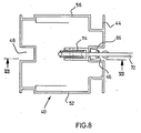
- a hollow support 10 which is made of sheet steel and has a cross section of about 90 x 90 mm in the support area.
- the hollow support 10 has at its lower end a base plate 12 which is firmly connected to it, preferably welded to it, with dimensions of approx. 380 x 180 x 15 mm, which is provided with four screw holes 14, by means of which the base plate is doweled with the base can.
- Two threaded holes 16 are used to receive an adjusting screw 18 with a lock nut.
- 1 and 2 are preferably arranged in the third points of the 9.75.m long side wall of a squash field, optionally also in the game wall at various spaced-apart locations, and there firmly with the hollow supports 10 or loader U-profiles spaced plastic-coated chipboard 20, 22 connected, preferably glued, which makes it possible to align and stiffen the wall in question both horizontally and vertically without affecting the critical rebound properties of the wall in a negative way would.
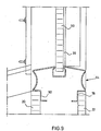
- Fig. 3 shows two abutting squash playing fields with playing areas 24 and 26.
- a play wall generally designated 28
- side wall 30 is located on the front side of the two playing areas 24, 26.
- the playing surface 26 shown at the top in FIG. 3 is delimited on its side facing away from the playing wall 28 by an input wall 32, while a glass wall 34 is located at the corresponding point on the playing surface 24.
- the game walls 28, the side wall 30 and the input wall 32 are each constructed in the manner known in principle from DE-OS 27 31 484 from particle boards 20, 22, which are made of aluminum or steel by U-profiles 36 serving as vertical wall closures, furthermore kept at a distance by vertical profiles, preferably I-profiles made of aluminum, which are arranged at a distance in the plate interspace 38 and are spaced apart.
- the pressboard 20, 22 consist of highly compressed material with a comparatively large proportion of phenolic resin, the large-area pressboard forming the walls of the squash field being constructed from individual plates which are seamlessly bonded to one another on the spot.
- the pressboard 20, 22 are coated at the factory with a two-component polyurethane system with flame-retardant additives as a primer, which cause flame resistance.
- the coating system is a low-solvent coating system, with a double primer with the material available under the trade name Pefalon 115 Primer FH preferably being used as the coating at the factory.
- abutting chipboards are then glued together seamlessly horizontally, but possibly also vertically, whereby the two-component material available under the trade name COMPAKTA PU adhesive VP 621-007, for example, can be used directly on the glue points when assembling.
- the adhesive is strongly pressed together during the horizontal bonding, whereby the excess material is pressed out laterally. After drying for about 1 to 2 days, the excess material is repelled, whereupon the surface is coated with a synthetic resin spatula, for example one under the trade name Metall-Spachtel SCHRAMM 616/83/7500 GFS 022 available two-component filler can be used.
- a synthetic resin spatula for example one under the trade name Metall-Spachtel SCHRAMM 616/83/7500 GFS 022 available two-component filler can be used.
- a top coating by means of a two-component water-based paint system with highly abrasion-resistant paint resins based on epoxy resin, also with flame-retardant additives, preferably a material available under the trade name Pefalon-XL top coating can be used.
- This final coating is precisely adapted to the needs of the squash game both in its color and in the degree of roughness, preferably by adding sand according to the
- the space between the plates 38 is filled with annealed, i.e. fire-dried quartz sand with a grain size of 1-3 mm, the smaller the grain size, the smaller the grain, the smaller the momentum that returns the ball to the playing field after hitting one of the walls.
- annealed i.e. fire-dried quartz sand with a grain size of 1-3 mm
- Fig. 3 also shows a serving as a vertical wall closure and for connecting adjoining walls, in the embodiment shown the side wall 30 and the input wall 32 and the glass wall 34, hollow support profile 40, which has a substantially square basic cross section in horizontal section.
- Two mutually opposite side surfaces 42, 44 of the support profile 40 have external central longitudinal grooves 46, 48 which run symmetrically to the longitudinal axis of the profile and which are arranged to accommodate wall attachments (e.g., as arranged above the actual walls 28, 30, 32, 34 to be described) 50 shown in Fig. 9) serve.
- the two essentially flat side surfaces 52, 54 arranged perpendicular to the side surfaces 42, 44 of the support profile 40 are essentially continuous, so that here, as in the rest of the case, also in the manner shown in FIG. 3, on the side surfaces 44, 42 , vertical U-profiles 36 serving to close the wall, in particular can be screwed on, but in each case a corner shoulder 56, 58 is provided in the edge area of the side surfaces 62, 54 facing the side surface 44, which is intended for receiving a glass wall 34 or the like, but can also serve to receive the protruding longitudinal edge region of pressboard plates 20, 22 over the U-profile 36, as shown in FIG. 3 at the top right for the case of the corner heel 58 and the pressboard plate 20.
- the support profiles 40 which are preferably made of aluminum, are installed, for example, in the manner shown in FIG. 3 on the rear of the side walls 30, i.e. thus they are located in the transition area from side wall 30 and rear wall 32 or 34.
- the support profiles 40 can have both glass panes 34 and normal playing field walls, for example 30 or 32, and also wall attachments 50 (FIG. 9) in their corresponding form vertical vertical grooves 46, 38 or corner shoulders 56, 58 or recesses 60, 62 or connected to the corresponding U-profiles 36, in particular screwed.
- FIG. 4 shows a side view of a side wall 30 of the type already described, the upper edge of which from the game wall 28 (shown on the right in FIG. 4) to the entrance wall 32 (shown on the left in FIG. 4) slopes obliquely in the manner customary for squash courts runs below.
- a profiled section 64 is provided as the upper end of the side wall 30, the details of which are described in detail below with reference to FIG. 9.
- An identical profile 64 also runs along the upper edge of the game wall 26, the details "A", "B” and “C” of FIG. 4 being explained and described in more detail below.
- FIG. 5 and 6 show the detail "A" of FIG. 4.
- the support profile 40 there has on its side facing the side wall 30 of FIG. 4 in the central longitudinal groove 46 a curtain rail-like fastening device 66 which 4 by means of hook elements 68, the side catch 44 in this exemplary embodiment are provided in the manner of a flange over the corner tabs ---. + 2e 58 and 56 in the manner which is further evident from the drawing, whereby the Corner shoulders 56, 58 are formed into longitudinal grooves.
- FIG. 9 shows the cut-out profile 64 shown schematically there with the wall attachment 50 already mentioned in section.
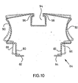
- the details of the profile 64 which serves as a horizontal wall finish and Which, essentially U-shaped, engages with its legs 78, 80 between the chipboard 20, 22 at its upper edge, are explained in detail below with reference to FIG. 10.
- the profiled section 64 shown in FIG. 10, as already stated, has a substantially U-shaped basic cross section, is made from resilient steel sheet with a thickness of approximately 1.25 mm.
- the legs 80, 82 are essentially bent at right angles at the end.
- a substantially rectangular corner recess 86, 88 is provided in connection with the corner flanges 82, 84 thus formed.
- a concave outline 90, 92 adjoins the corner recesses 86, 87 on both sides of the profile.
- the profile 64 On its web side, the profile 64 has an external, central longitudinal groove 94 into which the web of the U-profile merges with the formation of two internal longitudinal grooves 96, 98 with an essentially rectangular cross section.
- the profiled section 64 is used in such a way that the legs 80, 82 are brought from the position shown in broken lines in FIG. 10 by bending together into the position shown in solid lines and in this way are introduced into the plate space between pressboard plates 20, 22, whereby 9, the edge sections of the plates are then seated in the corner recesses 86, 88 in the manner shown in FIG. 9, the profiled section reliably remaining in the edge region of the space between the plates due to the resilient effect of the steel plate used.
- the longitudinal groove 94 can be used for receiving a wall attachment 50 or the like, as can also be seen in FIG. 9.
- the concave lines 90, 92 ensure reliable jumping of the ball and thus immediate recognition of a ball that is no longer valid, the walls of the squash court being optimally stiffened by the introduction of the profile 64.
- the entire profile 64 is preferably dashed in red, so that the lines 90, 92 are clearly visible.
Landscapes
- Engineering & Computer Science (AREA)
- Architecture (AREA)
- Civil Engineering (AREA)
- Structural Engineering (AREA)
- Finishing Walls (AREA)
- Pinball Game Machines (AREA)
- Laminated Bodies (AREA)
- Floor Finish (AREA)
- Building Environments (AREA)
Claims (21)
Priority Applications (1)
| Application Number | Priority Date | Filing Date | Title |
|---|---|---|---|
| AT82103828T ATE18275T1 (de) | 1981-10-28 | 1982-05-05 | Squash-spielfeld mit durch kunststoffbeschichtete pressspanplatten gebildeten waenden. |
Applications Claiming Priority (2)
| Application Number | Priority Date | Filing Date | Title |
|---|---|---|---|
| DE3142809A DE3142809C2 (de) | 1981-10-28 | 1981-10-28 | Squash-Spielfeld mit durch kunststoffbeschichtete Preßspanplatten gebildeten Wänden |
| DE3142809 | 1981-10-28 |
Publications (2)
| Publication Number | Publication Date |
|---|---|
| EP0077875A1 EP0077875A1 (fr) | 1983-05-04 |
| EP0077875B1 true EP0077875B1 (fr) | 1986-02-26 |
Family
ID=6145055
Family Applications (1)
| Application Number | Title | Priority Date | Filing Date |
|---|---|---|---|
| EP82103828A Expired EP0077875B1 (fr) | 1981-10-28 | 1982-05-05 | Court de squash à parois constituées de panneaux de couches de matières plastiques pressées |
Country Status (3)
| Country | Link |
|---|---|
| EP (1) | EP0077875B1 (fr) |
| AT (1) | ATE18275T1 (fr) |
| DE (2) | DE3142809C2 (fr) |
Families Citing this family (4)
| Publication number | Priority date | Publication date | Assignee | Title |
|---|---|---|---|---|
| DE3228279A1 (de) * | 1982-07-29 | 1984-02-02 | Squash Court Service GmbH, 2100 Hamburg | Vorrichtung zur farbigen markierung einer auslinie auf einer wand eines squashplatzes durch eine auf der wand zu befestigende leiste |
| JPS6055977A (ja) * | 1983-09-02 | 1985-04-01 | ホルスト バビンスキー | プラスチツク被覆プレスボードからなる壁を有するスカツシユコート |
| DE3403848A1 (de) * | 1983-11-07 | 1985-08-14 | Horst 8225 Traunreut Babinsky | Wandkonstruktion sowie verfahren zur ertuechtigung einer begrenzungswand eines squash-spielhofes |
| DE102010034733B4 (de) * | 2010-08-19 | 2019-05-16 | Horst Babinsky | Wandkonstruktion für ein Squash-Spielfeld und Squash-Spielfeld |
Family Cites Families (5)
| Publication number | Priority date | Publication date | Assignee | Title |
|---|---|---|---|---|
| GB1429635A (en) * | 1972-03-17 | 1976-03-24 | Richardson D S | Squash court |
| US4068840A (en) * | 1976-08-09 | 1978-01-17 | Spaulding Jr Charles A | Playing surface for handball and racquetball courts |
| DE2731484C2 (de) * | 1977-07-12 | 1983-01-05 | Horst 8225 Traunreut Babinsky | Squash-Spielfeld |
| DE2844393A1 (de) * | 1978-10-12 | 1980-05-08 | Christian Warnick | Spielwand fuer squash-sportfelder |
| DE2927910A1 (de) * | 1979-07-11 | 1981-01-29 | Ila Bau Gmbh & Co Kg | Bausatz zum errichten einer gebaeudewand |
-
1981
- 1981-10-28 DE DE3142809A patent/DE3142809C2/de not_active Expired
-
1982
- 1982-05-05 DE DE8282103828T patent/DE3269311D1/de not_active Expired
- 1982-05-05 EP EP82103828A patent/EP0077875B1/fr not_active Expired
- 1982-05-05 AT AT82103828T patent/ATE18275T1/de active
Also Published As
| Publication number | Publication date |
|---|---|
| DE3269311D1 (en) | 1986-04-03 |
| DE3142809A1 (de) | 1983-05-11 |
| DE3142809C2 (de) | 1985-06-05 |
| EP0077875A1 (fr) | 1983-05-04 |
| ATE18275T1 (de) | 1986-03-15 |
Similar Documents
| Publication | Publication Date | Title |
|---|---|---|
| DE4226742A1 (de) | Verkleidungselement für Böden, Decken, Wände und Fassaden | |
| DE2636531A1 (de) | Fertigbauelement | |
| EP0378725A1 (fr) | Piste pour planche à roulettes fabriquée à partir d'éléments uniques | |
| EP0077875B1 (fr) | Court de squash à parois constituées de panneaux de couches de matières plastiques pressées | |
| DE3229262A1 (de) | Plattenfoermiges bauelement aus holz | |
| DE3152991A1 (de) | Squash-Spielfeld mit horizontalem Wandabschluß | |
| DE2731484C2 (de) | Squash-Spielfeld | |
| DE8131541U1 (de) | Squash-Spielfeld mit durch kunststoffbeschichtete Preßspanplatten gebildeten Wänden | |
| DE3152993A1 (de) | Squash-spielfeld mit stuetzkonstruktion fuer die spielwaende | |
| WO1984001598A1 (fr) | Installation de separation pour huisserie de porte sur planchers de hauteurs differentes | |
| AT15447U1 (de) | Backkork-Fassadensockelplatte und Wärmedämmverbundsystem mit Backkork-Fassadensockelplatte | |
| DE3152992A1 (de) | Squash-spielfeld mit eckstuetzen | |
| DE19738571B4 (de) | Schrankwand | |
| CH683443A5 (de) | Blockhausartiges Gebäude. | |
| DE4302006C2 (de) | Gerüstverbundbohle | |
| DE202019106901U1 (de) | Sichtblendensystem für den Außenbereich | |
| DE3225513A1 (de) | Plattenfoermiges bauteil mit an den raendern angebrachten verbindungs-profilstaeben | |
| DE8708808U1 (de) | Schallabsorbierende und reflektierende Wand mit Wandverkleidung | |
| DE3520066C2 (fr) | ||
| DE10218855B4 (de) | Plattenförmiges Bauelement | |
| DE19522740C2 (de) | Vorrichtung zum Schutz des Mauerwerks von Bauwerken gegen Hochwasser | |
| DE3442759C2 (fr) | ||
| DE3636874A1 (de) | Kantenschutzprofil, insbesondere treppenvorstossschiene und verfahren zu dessen befestigung an einer trittstufe | |
| DE3504657C2 (fr) | ||
| DE9115434U1 (de) | Bausatz für Kinderspielplätze zum Errichten von Spielbauten |
Legal Events
| Date | Code | Title | Description |
|---|---|---|---|
| PUAI | Public reference made under article 153(3) epc to a published international application that has entered the european phase |
Free format text: ORIGINAL CODE: 0009012 |
|
| AK | Designated contracting states |
Designated state(s): AT CH DE FR GB IT LI NL SE |
|
| 17P | Request for examination filed |
Effective date: 19831013 |
|
| GRAA | (expected) grant |
Free format text: ORIGINAL CODE: 0009210 |
|
| AK | Designated contracting states |
Designated state(s): AT CH DE FR GB IT LI NL SE |
|
| PG25 | Lapsed in a contracting state [announced via postgrant information from national office to epo] |
Ref country code: NL Effective date: 19860226 Ref country code: IT Free format text: LAPSE BECAUSE OF FAILURE TO SUBMIT A TRANSLATION OF THE DESCRIPTION OR TO PAY THE FEE WITHIN THE PRESCRIBED TIME-LIMIT;WARNING: LAPSES OF ITALIAN PATENTS WITH EFFECTIVE DATE BEFORE 2007 MAY HAVE OCCURRED AT ANY TIME BEFORE 2007. THE CORRECT EFFECTIVE DATE MAY BE DIFFERENT FROM THE ONE RECORDED. Effective date: 19860226 Ref country code: FR Free format text: THE PATENT HAS BEEN ANNULLED BY A DECISION OF A NATIONAL AUTHORITY Effective date: 19860226 |
|
| REF | Corresponds to: |
Ref document number: 18275 Country of ref document: AT Date of ref document: 19860315 Kind code of ref document: T |
|
| PG25 | Lapsed in a contracting state [announced via postgrant information from national office to epo] |
Ref country code: SE Effective date: 19860228 |
|
| REF | Corresponds to: |
Ref document number: 3269311 Country of ref document: DE Date of ref document: 19860403 |
|
| PGFP | Annual fee paid to national office [announced via postgrant information from national office to epo] |
Ref country code: AT Payment date: 19860521 Year of fee payment: 5 |
|
| NLV1 | Nl: lapsed or annulled due to failure to fulfill the requirements of art. 29p and 29m of the patents act | ||
| EN | Fr: translation not filed | ||
| PLBE | No opposition filed within time limit |
Free format text: ORIGINAL CODE: 0009261 |
|
| STAA | Information on the status of an ep patent application or granted ep patent |
Free format text: STATUS: NO OPPOSITION FILED WITHIN TIME LIMIT |
|
| 26N | No opposition filed | ||
| PG25 | Lapsed in a contracting state [announced via postgrant information from national office to epo] |
Ref country code: AT Effective date: 19870505 |
|
| PG25 | Lapsed in a contracting state [announced via postgrant information from national office to epo] |
Ref country code: LI Effective date: 19870531 Ref country code: CH Effective date: 19870531 |
|
| REG | Reference to a national code |
Ref country code: CH Ref legal event code: PL |
|
| PGFP | Annual fee paid to national office [announced via postgrant information from national office to epo] |
Ref country code: GB Payment date: 20010502 Year of fee payment: 20 |
|
| PGFP | Annual fee paid to national office [announced via postgrant information from national office to epo] |
Ref country code: DE Payment date: 20010531 Year of fee payment: 20 |
|
| REG | Reference to a national code |
Ref country code: GB Ref legal event code: IF02 |
|
| PG25 | Lapsed in a contracting state [announced via postgrant information from national office to epo] |
Ref country code: GB Free format text: LAPSE BECAUSE OF EXPIRATION OF PROTECTION Effective date: 20020504 |
|
| REG | Reference to a national code |
Ref country code: GB Ref legal event code: PE20 Effective date: 20020504 |