EP0077990A1 - Method of applying cover members to play-balls - Google Patents
Method of applying cover members to play-balls Download PDFInfo
- Publication number
- EP0077990A1 EP0077990A1 EP82109584A EP82109584A EP0077990A1 EP 0077990 A1 EP0077990 A1 EP 0077990A1 EP 82109584 A EP82109584 A EP 82109584A EP 82109584 A EP82109584 A EP 82109584A EP 0077990 A1 EP0077990 A1 EP 0077990A1
- Authority
- EP
- European Patent Office
- Prior art keywords
- magazine
- cover part
- ball
- cover
- cover parts
- Prior art date
- Legal status (The legal status is an assumption and is not a legal conclusion. Google has not performed a legal analysis and makes no representation as to the accuracy of the status listed.)
- Granted
Links
- 238000000034 method Methods 0.000 title claims abstract description 12
- 238000005096 rolling process Methods 0.000 claims abstract description 6
- 239000003292 glue Substances 0.000 claims abstract description 3
- 230000000295 complement effect Effects 0.000 claims description 3
- 230000002093 peripheral effect Effects 0.000 claims description 2
- 239000000853 adhesive Substances 0.000 claims 1
- 230000001070 adhesive effect Effects 0.000 claims 1
- 238000004026 adhesive bonding Methods 0.000 description 4
- 238000003825 pressing Methods 0.000 description 3
- 238000003780 insertion Methods 0.000 description 2
- 230000037431 insertion Effects 0.000 description 2
- 239000011248 coating agent Substances 0.000 description 1
- 238000000576 coating method Methods 0.000 description 1
- 238000000151 deposition Methods 0.000 description 1
- 238000002360 preparation method Methods 0.000 description 1
- 238000004073 vulcanization Methods 0.000 description 1
Images


Classifications
-
- B—PERFORMING OPERATIONS; TRANSPORTING
- B29—WORKING OF PLASTICS; WORKING OF SUBSTANCES IN A PLASTIC STATE IN GENERAL
- B29D—PRODUCING PARTICULAR ARTICLES FROM PLASTICS OR FROM SUBSTANCES IN A PLASTIC STATE
- B29D22/00—Producing hollow articles
- B29D22/04—Spherical articles, e.g. balls
-
- B—PERFORMING OPERATIONS; TRANSPORTING
- B29—WORKING OF PLASTICS; WORKING OF SUBSTANCES IN A PLASTIC STATE IN GENERAL
- B29C—SHAPING OR JOINING OF PLASTICS; SHAPING OF MATERIAL IN A PLASTIC STATE, NOT OTHERWISE PROVIDED FOR; AFTER-TREATMENT OF THE SHAPED PRODUCTS, e.g. REPAIRING
- B29C63/00—Lining or sheathing, i.e. applying preformed layers or sheathings of plastics; Apparatus therefor
- B29C63/0073—Lining or sheathing, i.e. applying preformed layers or sheathings of plastics; Apparatus therefor of non-flat surfaces, e.g. curved, profiled
-
- Y—GENERAL TAGGING OF NEW TECHNOLOGICAL DEVELOPMENTS; GENERAL TAGGING OF CROSS-SECTIONAL TECHNOLOGIES SPANNING OVER SEVERAL SECTIONS OF THE IPC; TECHNICAL SUBJECTS COVERED BY FORMER USPC CROSS-REFERENCE ART COLLECTIONS [XRACs] AND DIGESTS
- Y10—TECHNICAL SUBJECTS COVERED BY FORMER USPC
- Y10T—TECHNICAL SUBJECTS COVERED BY FORMER US CLASSIFICATION
- Y10T156/00—Adhesive bonding and miscellaneous chemical manufacture
- Y10T156/10—Methods of surface bonding and/or assembly therefor
- Y10T156/1002—Methods of surface bonding and/or assembly therefor with permanent bending or reshaping or surface deformation of self sustaining lamina
- Y10T156/1028—Methods of surface bonding and/or assembly therefor with permanent bending or reshaping or surface deformation of self sustaining lamina by bending, drawing or stretch forming sheet to assume shape of configured lamina while in contact therewith
- Y10T156/103—Encasing or enveloping the configured lamina
-
- Y—GENERAL TAGGING OF NEW TECHNOLOGICAL DEVELOPMENTS; GENERAL TAGGING OF CROSS-SECTIONAL TECHNOLOGIES SPANNING OVER SEVERAL SECTIONS OF THE IPC; TECHNICAL SUBJECTS COVERED BY FORMER USPC CROSS-REFERENCE ART COLLECTIONS [XRACs] AND DIGESTS
- Y10—TECHNICAL SUBJECTS COVERED BY FORMER USPC
- Y10T—TECHNICAL SUBJECTS COVERED BY FORMER US CLASSIFICATION
- Y10T156/00—Adhesive bonding and miscellaneous chemical manufacture
- Y10T156/17—Surface bonding means and/or assemblymeans with work feeding or handling means
- Y10T156/1702—For plural parts or plural areas of single part
- Y10T156/1744—Means bringing discrete articles into assembled relationship
- Y10T156/1763—Magazine stack directly contacting separate work
-
- Y—GENERAL TAGGING OF NEW TECHNOLOGICAL DEVELOPMENTS; GENERAL TAGGING OF CROSS-SECTIONAL TECHNOLOGIES SPANNING OVER SEVERAL SECTIONS OF THE IPC; TECHNICAL SUBJECTS COVERED BY FORMER USPC CROSS-REFERENCE ART COLLECTIONS [XRACs] AND DIGESTS
- Y10—TECHNICAL SUBJECTS COVERED BY FORMER USPC
- Y10T—TECHNICAL SUBJECTS COVERED BY FORMER US CLASSIFICATION
- Y10T156/00—Adhesive bonding and miscellaneous chemical manufacture
- Y10T156/17—Surface bonding means and/or assemblymeans with work feeding or handling means
- Y10T156/1785—Magazine stack directly contacting work
Definitions
- the invention relates to a method for covering balls, in particular tennis balls, with a cover layer, in which two substantially dumbbell-shaped cover parts are applied one after the other by rolling the ball core over the designed dumbbell-shaped cover parts onto a glued ball core, and one Device for its implementation.
- the aim of the present invention is to provide a method and a device for the allocation of game balls, with the aid of which a fully automated allocation of game balls, in particular tennis balls, is achieved with a significantly reduced design effort.
- the invention consists in that the cover parts are stacked into a magazine and the magazine is provided with a layer of glue in such a way that the cover parts are glued only on their peripheral surfaces, whereupon the glued ball cores are successively first in a longitudinal direction over the Magazine are rolled that the ball core, beginning with the touch of the uppermost cover part, a distance corresponding to the cover part length plus half of the intermediate gap covered and at the end of this path by means of a second pressing device over a blind section corresponding to a 1/2 ball circumference and 1/2 intermediate gap and extending transversely to the first pressing track and then over a further cover parts magazine.
- the invention provides a method for the allocation of game balls, in particular tennis balls, by means of which the allocation can be carried out fully automatically in online operation, manual handling no longer being necessary.
- the insertion of the cover parts in the single insert into the occupancy device, which is required in the known method, is eliminated, as is the insertion of the ball core into the position required for the gluing.
- the coating takes place in a two-phase operation, in which a complete covering of the ball core with a cover layer is achieved in preparation for the subsequent vulcanization step.
- the device according to the invention for carrying out the method described above consists of a flat work table with two mutually perpendicular covering tracks for the ball cores, in each of which a recess corresponding to the size of the cover parts is provided and above which a pressure and
- the feed device is arranged from two slides, one inside the other at an angle of 90 °, each with a ball guide groove the dimensions and movements of which are matched to one another and to the position of the recesses, such that the ball core is first rolled from the first slide over the first magazine and is transferred to the slide running transversely by a distance corresponding to half the cover part gap, whereupon the now partially occupied ball core is moved by moving the second carriage in the first carriage held in its end position over the second magazine, the front edge of which is approximately 3/4 ball circumference from the transfer line in such a way that the front edge of the cover part with visible seam distance engages in the bay of the already applied deck part.
- this structurally extremely simple device which consists of a roller table, a lifting device and the pressure and feed device formed from two mutually guided slides
- the placement of game balls can be carried out in a fully automated manner, with each ball being fully occupied with every two-phase work cycle .
- the cover parts but also the ball cores themselves can also be set up fully automatically with the aid of a funnel or belt inlet or another suitable transport device, at the outlet of which the balls are brought into contact with an inlet section of the first sled individually from below by means of a lifting device by moving the ball core is transferred to the roller table and transported to the document line.
- Such a device can consist, for example, of a conveyor belt for the glued ball cores provided with shells which are open at the bottom, and a lifting plate under the first pressure device, with the aid of which the ball cores are lifted individually from the feed conveyor belt until they come into contact with the pressure device.
- the document device can consist of a document table with two document tracks and a recess in each document track corresponding to the shape of the cover parts, under each of which a lifting device for the cyclical lifting of a cover part magazine by one cover part thickness is arranged, and one each Endless pressure and transport link belt with grooved links that complement one another to form a guideway for the ball core, which links are connected to one another by means of a conveyor belt that extends transversely to the link belt of the first loading table and at a distance that corresponds to the ball core thickness and extends parallel under the link belt of the second slip track , wherein the speeds of the conveyor belt and the link belt of the second covering track are coordinated with one another in such a way that the partially occupied ball core results due to the result of the two different rotational speeds Movement until the magazine of the second document path reaches a rotation of 270 ° forwards or 90 ° backwards.
- a continuous allocation of game balls can also be carried out in fully automated online operation, the throughput sequence being determined only by the time required for lifting the cover part magazine E after each ball core pass.
- the lifting device is advantageously provided with an elastically flexible or flexible covering.
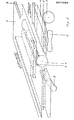
- 1 denotes a ball core and 2, 3 dumbbell-shaped covering parts, which are to be applied in an interlocking manner at an angle of 90 ° by rolling the glued ball core over the dumbbell-shaped cover parts laid out on the ball core 1.
- Fig. 1 of the drawing only one dumbbell-shaped cover part 2, 3 is shown schematically. It can therefore be assumed that a cover part magazine is provided instead of the individually shown dumbbell-shaped cover parts.
- a first pressure device in the form of a slide 4, which is located one above the other Magazine of the cover parts 2 or the corresponding table opening extending spherically curved pressure and guide channel 5 and can be moved back and forth in the direction of the longitudinal axis of the cover part magazine opening. This direction is defined in the drawing as "1st direction of movement”.
- a further slide 6 is also provided with a guide and pressure channel 7, which can be moved back and forth in a direction offset by 90 ° with respect to the slide 4, the guide channel extending in the longitudinal direction over the magazine of the cover parts 3 extends.
- either the first carriage 4 can be guided in the carriage 6 and this in turn can be guided in a table-fixed guide 8, but both carriages can also be guided separately in a table-fixed guide.
- Fig. 2 of the drawing in the rest of the corresponding parts with the same reference numerals as in Fig. 1, 9 denotes a conveyor belt, which is provided with downwardly open trays 10 and with the help of the ball cores 1 individually be brought into the area of the first carriage 4.
- a lifting plate 11 is located under the conveyor belt in the area of the slide 4, with the aid of which the ball core 1 can be lifted by reaching through the open shell 10 and brought into contact with the slide 4 or the guide channel 5.
- the work table of the device is shown at 12, in which there is an opening 13 corresponding to the contour of the cover parts, under which in turn a magazine carrier 14 is arranged.
- the magazine carrier can be lifted in cycles by one cover part thickness in such a way that the cover part 2 lying at the top of the magazine is in the plane of the work table.
- the lifting device used is a lifting plate 14 with two link belts 15 guiding the magazine on opposite side surfaces, but instead of which any other suitable lifting and guiding device can be provided.
- the ball core is first transported into the area of the slide 4 with the aid of the conveyor belt 9 and raised so far by means of the lifting plate 11 that the ball core comes into contact with the guide channel 5. Then the carriage 4 - see FIG. 1 - is moved in the first direction of movement, the ball core 1 being rolled on the work table over the cover part magazine 2, from which it removes the top cover part by gluing due to its surface gluing. By appropriate advancement of the carriage 4, the now partially occupied ball core is released from the carriage 4 and reaches the region of the guide channel 7, from which it is gripped and rolled over the second cover part magazine 3 by movement of the carriage 6 in the second direction of movement from which he removes the top cover part with gluing in the same way.
- the movement distances and track spacings are coordinated with one another in such a way that the two dumbbell-shaped cover parts are applied in an interlocking manner at an angle of 90 ° and the loop seam typical for balls thus occupied is formed.
- the occupancy process is now complete and the sledges are returned to their starting position for taking over and occupying the next ball core.
- a loading table 12 is also provided with recesses 13 corresponding to the shape of the cover parts 2, under each of which there is a lifting device for the cyclical lifting of a cover part magazine by one cover part thickness is arranged.
- the pressure device consists of a link belt 16 or 17 with grooved links which complement one another to form a guide track for the ball core and which extend parallel to the link belt by means of a distance which extends transversely to the link belt 16 of the first covering track and at a distance corresponding to the ball thickness of the second document track reaching conveyor belt 19 are connected to one another, the speeds of the conveyor belt 19 and the link belt 17 of the second document track being matched to one another such that the partially occupied ball core due to the due to the two different speeds of rotation resulting movement until reaching the magazine of the second document web makes a rotation of about 270 ° forwards or 90 ° backwards in such a way that the front edge of the cover part adjoins the bay edge of the cover part already applied with a visible seam distance.
- the balls can be continuously occupied in a short time cycle and without interruption because the device must be returned to the zero position.
Landscapes
- Engineering & Computer Science (AREA)
- Mechanical Engineering (AREA)
- Manufacturing & Machinery (AREA)
- Delivering By Means Of Belts And Rollers (AREA)
- Adhesives Or Adhesive Processes (AREA)
- Automatic Assembly (AREA)
Abstract
Verfahren zum Belegen von Spielbällen, insbesondere Tennisbällen, bei dem auf einen beleimten Ballkern (1) zwei im wesentlichen hantelförmige Deckteile (2, 3) in einem Winkel von 90° ineinandergreifend nacheinader durch Rollen über die ausgelegten hantelförmigen Deckteile (2, 3) aufgebracht werden. Es werden die Deckteile (2, 3) zu einem Magazin gestapelt und derart mit einer Leimschicht versehen, daß die Deckteile (2, 3) nur an ihren Umfangsflächen beleimt sind, worauf die beleimten Ballkerne (1) nacheinander zunächst mittels eine Andruckeinrichtung (4, 16) in Längsrichtung über ein erstes Druckteilemagazin und anschließend mittels einer zweiten. sich quer zur ersten Andruckbahn erstreckenden Andruckeinrichtung (6, 17) über eine etwa 3/4 Ballumfang entsprechende Blindstrecken und danach über ein weiteres Deckteilemagazin gerollt werden derart, daß die Kante des zweiten Deckteiles (3) mit Ziernahtabstand in die Bucht des bereits aufgebrachten Deckteiles (2) eingreift.Method for covering game balls, in particular tennis balls, in which two essentially dumbbell-shaped cover parts (2, 3) are applied to one another at a glued ball core (1) at an angle of 90 ° one after the other by rolling over the dumbbell-shaped cover parts (2, 3) . The cover parts (2, 3) are stacked to form a magazine and provided with a glue layer in such a way that the cover parts (2, 3) are glued only on their circumferential surfaces, whereupon the glued ball cores (1) are successively first applied by means of a pressure device (4, 16) in the longitudinal direction via a first pressure parts magazine and then by means of a second. the pressure device (6, 17), which extends transversely to the first pressure track, is rolled over a blind distance corresponding to approximately 3/4 ball circumference and then over a further cover part magazine in such a way that the edge of the second cover part (3) with a decorative seam distance into the bay of the cover part already applied ( 2) intervenes.
Description
Die Erfindung betrifft ein Verfahren zum Belegen von Spielbällen, insbesondere von Tennisbällen mit einem Deckbelag, bei dem auf einen beleimten Ballkern zwei im wesentlichen hantelförmige Deckteile in einem Winkel von 90° ineinandergreifend nacheinander durch Rollen des Ballkernes über die ausgelegten hantelförmigen Deckteile aufgebracht werden, sowie eine Vorrichtung zu seiner Durchführung.The invention relates to a method for covering balls, in particular tennis balls, with a cover layer, in which two substantially dumbbell-shaped cover parts are applied one after the other by rolling the ball core over the designed dumbbell-shaped cover parts onto a glued ball core, and one Device for its implementation.
Es ist aus der US-PS 2 509 528 eine Einrichtung zum Belegen von Spielbällen, insbesondere Tennisbällen, bekannt geworden, die aus einem Rundlauftisch mit insgesamt sechs im wesentlichen gleichgestalteten Arbeitstischen besteht, in die jeweils zwei Deckteile und ein Ballkern von Hand eingelegt werden und die nacheinander an fünf Arbeitsköpfen angestellt werden, von denen aktweise die verschiedenen Rollvorgänge zum Andrücken der Deckteile an den Ballkern ausgeführt werden. Bei der bekannten Einrichtung handelt es sich um eine konstruktiv außerordentlich aufwendige Einrichtung, wobei trotz des erheblichen konstruktiven Aufwandes nur ein teilautomatischer Arbeitsablauf erreicht wird insofern, als sowohl die beiden Deckteile als auch der Ballkern einzeln manuell in die Einrichtung eingelegt werden müssen, wobei bei einem Umlauf des Arbeitstisches nur jeweils ein Ball fertiggestellt werden kann.It has become known from US-PS 2 509 528 a device for covering game balls, especially tennis balls, which consists of a rotary table with a total of six essentially identical work tables, in each of which two deck parts and a ball core are inserted by hand and the to one another are employed on five working heads, of which the various rolling processes for pressing the cover parts against the core of the ball are carried out. The known device is a structurally extremely complex device, and despite the considerable design effort, only a partially automatic workflow is achieved insofar as both the two cover parts and the ball core have to be manually inserted individually into the device, with one cycle only one ball can be completed on the work table.
Ziel der vorliegenden Erfindung ist die Schaffung eines Verfahrens und einer Vorrichtung zum Belegen von Spielbällen, mit deren Hilfe bei wesentlich verringertem konstruktivem Aufwand eine vollautomatisierte Belegung von Spielbällen, insbesondere Tennisbällen erreicht wird. Die Erfindung besteht darin, daß die Deckteile zu mehreren zu einem Magazin gestaptelt werden und das Magazin derart mit einer Leimschicht versehen wird, daß die Deckteile nur an ihren Umfangsflächen beleimt sind, worauf die beleimten Ballkerne nacheinander zunächst mittels einer ersten Andruckeinrichtung derart in Längsrichtung über das Magazin gerollt werden, daß der Ballkern beginnend mit der Berührung des zuoberst liegenden Deckteiles eine der Deckteillänge zuzüglich der Hälfte des Zwischenspaltes entsprechende Wegstrecke zurücklegt und am Ende dieses Weges mittels einer zweiten Andruckeinrichtung über eine einem 1/2 Ballumfanq und 1/2 Zwischenspalt entsprechende, sich quer zur ersten Andruckbahn erstreckende Blindstrecke und danach über ein weiteres Deckteilemagazin gerollt wird.The aim of the present invention is to provide a method and a device for the allocation of game balls, with the aid of which a fully automated allocation of game balls, in particular tennis balls, is achieved with a significantly reduced design effort. The invention consists in that the cover parts are stacked into a magazine and the magazine is provided with a layer of glue in such a way that the cover parts are glued only on their peripheral surfaces, whereupon the glued ball cores are successively first in a longitudinal direction over the Magazine are rolled that the ball core, beginning with the touch of the uppermost cover part, a distance corresponding to the cover part length plus half of the intermediate gap covered and at the end of this path by means of a second pressing device over a blind section corresponding to a 1/2 ball circumference and 1/2 intermediate gap and extending transversely to the first pressing track and then over a further cover parts magazine.
Durch die Erfindung ist ein Verfahren zum Belegen von Spielbällen, insbesondere Tennisbällen, geschaffen, mit dessen Hilfe die Belegung im On-Line-Betrieb vollautomatisiert erfolgen kann, wobei eine manuelle Handhabung nicht mehr erforderlich ist. Das bei dem bekannten Verfahren erforderliche Einlegen der Deckteile in Einzeleinlage in die Belegungseinrichtung entfällt, ebenso das Einlegen des Ballkernes in die für die Verklebung erforderliche Stellung. Die Belegung erfolgt in einem zweiphasigen Arbeitsgang, in dem eine vollständige Belegung des Ballkernes mit einer Deckschicht als Vorbereitung für die nachfolgende Vulkanisierstufe erreicht wird.The invention provides a method for the allocation of game balls, in particular tennis balls, by means of which the allocation can be carried out fully automatically in online operation, manual handling no longer being necessary. The insertion of the cover parts in the single insert into the occupancy device, which is required in the known method, is eliminated, as is the insertion of the ball core into the position required for the gluing. The coating takes place in a two-phase operation, in which a complete covering of the ball core with a cover layer is achieved in preparation for the subsequent vulcanization step.
In einer - taktweise arbeitenden - Ausführungsform besteht die erfindungsgemäße Vorrichtung zur Durchführung des vorstehend beschriebenen Verfahrens aus einem ebenen Arbeitstisch mit zwei rechtwinklig zueinander stehenden Belegbahnen für die Ballkerne, in denen jeweils eine der Größe der Deckteile entsprechende Ausnehmung vorgesehen ist und über dem eine Andruck- und Vorschubeinrichtung aus zwei in einem Winkel von 90° ineinander geführten, jeweils eine Ballführungskehlung aufweisenden Schlitten angeordnet ist, deren Dimensionierung und Bewegungen derart aufeinander und auf die Lage der Ausnehmungen abgestimmt sind, daß der Ballkern zunächst von dem ersten Schlitten über das erste Magazin gerollt und durch weiteren Vorschub um eine dem halben Deckteilspalt entsprechende Strecke auf den hierzu quer verlaufenden Schlitten übergeben wird, worauf der nunmehr teilbelegte Ballkern durch Bewegung des zweiten Schlittens in dem in seiner Endstellung gehaltenen ersten Schlitten über das zweite Magazin gerollt wird, dessen Vorderkante sich in einem etwa dem 3/4 Ballkernumfang entsprechenden Abstand von der Übergabelinie befindet derart, daß die vordere Deckteilkante mit Sichtnahtabstand in die Bucht des bereits aufgebrachten Deckteils eingreift.In one - intermittently working - embodiment, the device according to the invention for carrying out the method described above consists of a flat work table with two mutually perpendicular covering tracks for the ball cores, in each of which a recess corresponding to the size of the cover parts is provided and above which a pressure and The feed device is arranged from two slides, one inside the other at an angle of 90 °, each with a ball guide groove the dimensions and movements of which are matched to one another and to the position of the recesses, such that the ball core is first rolled from the first slide over the first magazine and is transferred to the slide running transversely by a distance corresponding to half the cover part gap, whereupon the now partially occupied ball core is moved by moving the second carriage in the first carriage held in its end position over the second magazine, the front edge of which is approximately 3/4 ball circumference from the transfer line in such a way that the front edge of the cover part with visible seam distance engages in the bay of the already applied deck part.
Mit Hilfe dieser konstruktiv außerordentlich einfachen, lediglich aus einem Rolltisch, einer Hubvorrichtung und der aus zwei ineinandergeführten Schlitten gebildeten Andruck- und Vorschubeinrichtung gebildeten Vorrichtung kann in taktweisem Betrieb vollautomatisiert das Belegen von Spielbällen erfolgen, wobei mit jedem lediglich zweiphasigen Arbeitstakt das vollständige Belegen eines Spielballes erfolgt. Hierbei kann das Anstellen nicht nur der Deckteile sondern auch der Ballkerne selbst ebenfalls vollautomatisch mit Hilfe eines Trichter- oder Bandeinlaufes oder einer anderen geeigneten Transporteinrichtung erfolgen, an deren Auslauf die Bälle taktweise einzeln von unten mittels einer Hubeinrichtung in Anlage an eine Einlaufstrecke des ersten Schlittens gebracht werden, durch dessen Bewegung der Ballkern auf den Rolltisch überführt und in die Belegstrecke transportiert wird. Eine derartige Einrichtung kann etwa aus einem mit nach unten offenen Schalen versehenen Transportband für die beleimten Ballkerne sowie einem Hubteller unter der ersten Andruckeinrichtung bestehen, mit dessen Hilfe die Ballkerne einzeln von dem Zuführungstransportband bis zur Berührung mit der Andruckeinrichtung angehoben werden.With the help of this structurally extremely simple device, which consists of a roller table, a lifting device and the pressure and feed device formed from two mutually guided slides, the placement of game balls can be carried out in a fully automated manner, with each ball being fully occupied with every two-phase work cycle . Here, not only the cover parts but also the ball cores themselves can also be set up fully automatically with the aid of a funnel or belt inlet or another suitable transport device, at the outlet of which the balls are brought into contact with an inlet section of the first sled individually from below by means of a lifting device by moving the ball core is transferred to the roller table and transported to the document line. Such a device can consist, for example, of a conveyor belt for the glued ball cores provided with shells which are open at the bottom, and a lifting plate under the first pressure device, with the aid of which the ball cores are lifted individually from the feed conveyor belt until they come into contact with the pressure device.
In einer anderen Ausführungsform der Erfindung kann die Belegvorrichtung aus einem Belegtisch mit zwei Belegbahnen sowie jeweils einer der Form der Deckteile entsprechenden Ausnehmung in jeder Belegbahn bestehen, unter denen sich jeweils eine Hubeinrichtung zum taktweisen Heben eines Deckteilemagazines um jeweils eine Deckteilstärke angeordnet ist, sowie jeweils einem endlosen Andruck- und Transport-Gliederband mit gekehlten, sich zu einer Führungsbahn für den Ballkern ergänzenden Gliedern, die mittels eines sich quer zum Gliederband des ersten Belegtisches erstreckenden und in einem der Ballkerndicke entsprechenden Abstand parallel unter das Gliederband der zweiten Belegbahn reichenden Transportbandes miteinander verbunden sind, wobei die Geschwindigkeiten des Transportbandes und des Gliederbandes der zweiten Belegbahn derart aufeinander abgestimmt sind, daß der teilbelegte Ballkern aufgrund der durch die beiden unterschiedlichen Umlaufgeschwindigkeiten bewirkte resultierenden Bewegung bis zum Erreichen des Magazines der zweiten Belegbahn eine Drehung um 270° nach vorn oder 90° nach rückwärts ausführt.In another embodiment of the invention, the document device can consist of a document table with two document tracks and a recess in each document track corresponding to the shape of the cover parts, under each of which a lifting device for the cyclical lifting of a cover part magazine by one cover part thickness is arranged, and one each Endless pressure and transport link belt with grooved links that complement one another to form a guideway for the ball core, which links are connected to one another by means of a conveyor belt that extends transversely to the link belt of the first loading table and at a distance that corresponds to the ball core thickness and extends parallel under the link belt of the second slip track , wherein the speeds of the conveyor belt and the link belt of the second covering track are coordinated with one another in such a way that the partially occupied ball core results due to the result of the two different rotational speeds Movement until the magazine of the second document path reaches a rotation of 270 ° forwards or 90 ° backwards.
Mit Hilfe dieser Ausführungsform einer Belegeinrichtung kann in ebenfalls vollautomatisiertem On-Line-Betrieb eine kontinuierliche Belegung von Spielbällen vorgenommen werden, wobei die Durchlauffolge nur durch die für das Anheben des DeckteilemagazineE nach jedem Ballkerndurchlauf benötigte Zeit bestimmt wird.With the help of this embodiment of a depositing device, a continuous allocation of game balls can also be carried out in fully automated online operation, the throughput sequence being determined only by the time required for lifting the cover part magazine E after each ball core pass.
Zur Gewährleistung eines ausreichend flächigen Andruckes der Ballkerne an die Deckteile auch in den unteren Magazinbereichen, in denen der Deckteilestapel nur noch eine geringe Eigenflexibilität besitzt, ist die Hubeinrichtung vorteilhaft mit einem elastisch nachgiebigen bzw. flexiblen Belag versehen.In order to ensure that the ball cores are pressed sufficiently flat against the cover parts, even in the lower magazine areas, in which the stack of cover parts has little inherent flexibility, the lifting device is advantageously provided with an elastically flexible or flexible covering.
Die Erfindung ist in der Zeichnung bespielsweise veranschaulicht. Es zeigen
- Fig. l in perspektivischer Darstellung das Schema einer Belegeinrichtung für taktweisen Betrieb
- Fig. 2 eine Ballkernzuführungseinrichtung in schematischer Seitenansicht
- Fig. 3 eine Hubvorrichtung für ein Deckteilemagazin in schematischer Seitenansicht
- Fig. 4 eine perspektivisch-schematische Wiedergabe einer Belegeinrichtung für kontinuierlichen On-Line-Betrieb
- Fig. 5 eine schematische Seitenansicht des ersten Belegtisches der in Fig. 4 dargestellten Einrichtung.
- Fig. L is a perspective view of the scheme of a document device for cyclical operation
- Fig. 2 shows a ball core feed device in a schematic side view
- Fig. 3 shows a lifting device for a cover parts magazine in a schematic side view
- Fig. 4 is a perspective-schematic representation of a document device for continuous online operation
- Fig. 5 is a schematic side view of the first occupancy table of the device shown in Fig. 4.
In der Zeichnung sind mit 1 jeweils ein Ballkern und mit 2, 3 hantelförmige Belegteile bezeichnet, die in einem Winkel von 90° ineinandergreifend nacheinander durch Rollen des beleimten Ballkernes über die ausgelegten hantelförmigen Deckteile auf den Ballkern 1 aufgebracht werden sollen. In Fig. 1 der Zeichnung ist jeweils nur ein hantelförmiges Deckteil 2, 3 schematisch dargestellt. Es ist somit davon auszugehen, daß an Stelle der einzeln dargestellten hantelförmigen Deckteile jeweils ein Deckteilemagazin vorgesehen ist.In the drawing, 1 denotes a ball core and 2, 3 dumbbell-shaped covering parts, which are to be applied in an interlocking manner at an angle of 90 ° by rolling the glued ball core over the dumbbell-shaped cover parts laid out on the
Über dem Arbeitstisch befinden sich eine erste Andruckeinrichtung in Form eines Schlittens 4, der einen sich längs über dem Magazin der Deckteile 2 bzw. der entsprechenden Tischöffnung erstreckenden kugelig gewölbten Andruck- und Führungskanal 5 aufweist und in Richtung der Längsachse des Deckteilemagazinöffnunc hin- und herbewegbar ist. Diese Richtung ist in der Zeichnung mit "1. Bewegungsrichtung" definiert. Außer dem Schlitten 4 ist ein weiterer Schlitten 6 mit ebenfalls einem Führungs- und Andruckkanal 7 vorgesehen, der in einer um 90° gegenüber dem Schlitten 4 versetzt liegenden Richtung hin- und herbewegt werden kann,wobei sich der Führungskanal in Längsrichtung über dem Magazin der Deckteile 3 erstreckt. Hierbei kann entweder der erste Schlitten 4 in dem Schlitten 6 und dieser wiederum in einer tischfesten Führung 8 geführt sein, es können jedoch auch beide Schlitten gesondert in einer tischfesten Führung geführt werden.Above the work table are a first pressure device in the form of a
In Fig. 2 der Zeichnung, in der im übrigen die einander entsprechenden Teile mit denselben Bezugsziffern wie in Fig. 1 bezeichnet sind, ist mit 9 ein Transportband bezeichnet, das mit nach unten offenen Schalen 10 versehen ist und mit dessen Hilfe die Ballkerne 1 einzeln in den Bereich des ersten Schlittens 4 gebracht werden. Unter dem Transportband befindet sich im Bereich des Schlittens 4 ein Hubteller 11, mit dessen Hilfe unter Durchgriff durch die offene Schale 10 der Ballkern 1 angehoben und in Berührung mit dem Schlitten 4 bzw. dem Führungskanal 5 gebracht werden kann.In Fig. 2 of the drawing, in the rest of the corresponding parts with the same reference numerals as in Fig. 1, 9 denotes a conveyor belt, which is provided with downwardly
In Fig. 3 der Zeichnung ist mit 12 der Arbeitstisch der Einrichtung wiedergegeben, in dem sich eine der Kontur der Deckteile entsprechende Öffnung 13 befindet, unter der wiederum ein Magazinträger 14 angeordnet ist. Mit Hilfe einer Hubeinrichtung kann der Magazinträger taktweise um jeweils eine Deckteildicke derart angehoben werden, daß sich jeweils das an oberster Stelle des Magazines liegende Deckteil 2 in der Ebene des Arbeitstisches befindet. Als Hubvorrichtung dient im dargestellten Fall ein Hubteller 14 mit zwei das Magazin an gegenüberllegenden Seitenflächen führenden Gliederbandern 15, an deren Stelle jedoch auch jede andere geeignete Hub- und Führungseinrichtung vorgesehen sein kann.In Fig. 3 of the drawing, the work table of the device is shown at 12, in which there is an
Zur Belegung des Balles wird der Ballkern zunächst mit Hilfe des Transportbandes 9 in den Bereich des Schlittens 4 transportiert und mittels des Hubtellers 11 soweit angehoben, daß der Ballkern in Kontakt mit dem Führungskanal 5 gelangt. Danach wird der Schlitten 4 - siehe Fig. l - in der ersten Bewegungsrichtung bewegt, wobei der Ballkern 1 auf dem Arbeitstisch über das Deckteilemagazin 2 gerollt wird, von dem er aufgrund seiner Oberflächenbeleimung das oberste Deckteil unter Verklebung abnimmt. Durch entsprechenden Vorschub des Schlittens 4 kommt der nunmehr teilweise belegte Ballkern von dem Schlitten 4 frei und gelangt in den Bereich des Führungskanales 7, von dem er erfaßt und durch Bewegung des Schlittens 6 in der zweiten Bewegungsrichtung über das zweite Deckteilemagazin 3 gerollt wird, von dem er in gleicher Weise das oberste Deckteil unter Verklebung abnimmt. Hierbei sind die Bewegungsstrecken und Bahnenabstände derart aufeinander abgestimmt, daß die beiden hantelförmigen Deckteile in einem Winkel von 90° ineinandergreifend aufgebracht werden und die für derart belegte Bälle typische Schlingennaht gebildet wird. Der Belegungsvorgang ist damit abgeschlossen und die Schlitten werden in ihre Ausgangslage zur Übernahme und Belegung des nächsten Ballkernes zurückgeführt.To occupy the ball, the ball core is first transported into the area of the
Bei der in Fig. 4 und 5 wiedergegebenen, für On-Line-Betrieb geeigneten Ausführungsform ist ebenfalls ein Belegtisch 12 mit jeweils der Form der Deckteile 2 entsprechenden Ausnehmungen 13 vorgesehen, unter denen sich jeweils eine Hubvorrichtung zum taktweisen Heben eines Deckteilemagazines um jeweils eine Deckteilstärke angeordnet ist. Die Andruckeinrichtung besteht in diesem Falle aus jeweils einem Gliederband 16 bzw. 17 mit gekehlten, sich zu einer Führungsbahn für den Ballkern ergänzenden Gliedern, die mittels eines sich quer zum Gliederband 16 der ersten Belegbahn erstreckenden und in einem der Balldicke entsprechenden Abstand parallel unter das Gliederband der zweiten Belegbahn reichenden Transportbandes 19 miteinander verbunden sind, wobei die Geschwindigkeiten des Transportbandes 19 und des Gliederbandes 17 der zweiten Belegbahn derart aufeinander abgestimmt sind, daß der teilbelegte Ballkern aufgrund der durch die beiden unterschiedlichen Umlaufgeschwindigkeiten bewirkten resultierenden Bewegung bis zum Erreichen des Magazines der zweiten Belegbahn eine Drehung um etwa 270° nach vorn oder 90° nach rückwärts ausführt derart, daß die vordere Deckteilkante mit Sichtnahtabstand an die Buchtkante des bereits aufgebrachten Deckteiles anschließt. Mit Hilfe dieser Belegeinrichtung ist ein kontinuierliches Belegen der Bälle in kurzer Zeittaktfolge und ohne Unterbrechung wegen einer notwendigen Rückführung der Einrichtung in die Nullstellung möglich.In the embodiment shown in FIGS. 4 and 5, which is suitable for on-line operation, a loading table 12 is also provided with
Claims (6)
Applications Claiming Priority (4)
| Application Number | Priority Date | Filing Date | Title |
|---|---|---|---|
| DE3142065 | 1981-10-23 | ||
| DE3142065 | 1981-10-23 | ||
| DE3228341 | 1982-07-29 | ||
| DE3228341A DE3228341A1 (en) | 1981-10-23 | 1982-07-29 | METHOD FOR COVERING GAME BALLS WITH COVERING PARTS |
Publications (2)
| Publication Number | Publication Date |
|---|---|
| EP0077990A1 true EP0077990A1 (en) | 1983-05-04 |
| EP0077990B1 EP0077990B1 (en) | 1989-03-15 |
Family
ID=25796846
Family Applications (1)
| Application Number | Title | Priority Date | Filing Date |
|---|---|---|---|
| EP82109584A Expired EP0077990B1 (en) | 1981-10-23 | 1982-10-16 | Method of applying cover members to play-balls |
Country Status (3)
| Country | Link |
|---|---|
| US (1) | US4543143A (en) |
| EP (1) | EP0077990B1 (en) |
| DE (1) | DE3228341A1 (en) |
Families Citing this family (2)
| Publication number | Priority date | Publication date | Assignee | Title |
|---|---|---|---|---|
| DE3511882A1 (en) * | 1985-04-01 | 1986-10-09 | Stefan Dipl.-Ing. 5210 Troisdorf Siebertz | METHOD FOR PACKING TENNIS BARS |
| ITMI20071389A1 (en) * | 2007-07-12 | 2009-01-13 | System Plast Spa | SYSTEM OF MINI CONVEYORS |
Citations (3)
| Publication number | Priority date | Publication date | Assignee | Title |
|---|---|---|---|---|
| US2509528A (en) * | 1947-01-30 | 1950-05-30 | Roberts Robert Eldon | Apparatus for covering balls |
| GB642469A (en) * | 1947-03-05 | 1950-09-06 | Fred Thomas Roberts | Improved method and apparatus for covering balls |
| FR2128830A1 (en) * | 1971-03-12 | 1972-10-20 | Dunlop Holdings Ltd |
Family Cites Families (10)
| Publication number | Priority date | Publication date | Assignee | Title |
|---|---|---|---|---|
| US1117129A (en) * | 1911-07-14 | 1914-11-10 | Package Machinery Co | Wrapping-machine. |
| US1048092A (en) * | 1911-12-18 | 1912-12-24 | Frederick H Perry | Method of making base-balls. |
| US1117130A (en) * | 1914-03-05 | 1914-11-10 | Package Machinery Co | Wrapping-machine. |
| US1435680A (en) * | 1918-11-30 | 1922-11-14 | Allan A Adamson | Round-package-labeling machine |
| US1706384A (en) * | 1928-03-29 | 1929-03-19 | Pennsylvania Rubber Company | Tennis-ball-covering machine |
| US2045287A (en) * | 1935-05-17 | 1936-06-23 | M J B Company | Attachment for can labeling machines |
| US2299544A (en) * | 1939-05-09 | 1942-10-20 | Walter E Humphrey | Process and apparatus for covering balls |
| US3690435A (en) * | 1970-04-16 | 1972-09-12 | John W King | Article conveyor system |
| US4194941A (en) * | 1974-07-22 | 1980-03-25 | Fmc Corporation | Labelling machine |
| US4017003A (en) * | 1975-12-18 | 1977-04-12 | The Lakso Company, Incorporated | Article dispensing machine |
-
1982
- 1982-07-29 DE DE3228341A patent/DE3228341A1/en not_active Withdrawn
- 1982-10-16 EP EP82109584A patent/EP0077990B1/en not_active Expired
-
1984
- 1984-10-29 US US06/666,121 patent/US4543143A/en not_active Expired - Lifetime
Patent Citations (3)
| Publication number | Priority date | Publication date | Assignee | Title |
|---|---|---|---|---|
| US2509528A (en) * | 1947-01-30 | 1950-05-30 | Roberts Robert Eldon | Apparatus for covering balls |
| GB642469A (en) * | 1947-03-05 | 1950-09-06 | Fred Thomas Roberts | Improved method and apparatus for covering balls |
| FR2128830A1 (en) * | 1971-03-12 | 1972-10-20 | Dunlop Holdings Ltd |
Also Published As
| Publication number | Publication date |
|---|---|
| EP0077990B1 (en) | 1989-03-15 |
| DE3228341A1 (en) | 1983-05-05 |
| US4543143A (en) | 1985-09-24 |
Similar Documents
| Publication | Publication Date | Title |
|---|---|---|
| DE4107224C1 (en) | ||
| CH403811A (en) | Method and device for inserting inserts into folded envelope sheets | |
| EP0909728A1 (en) | Device and method for decorating objects | |
| DE3222657A1 (en) | DEVICE AND METHOD FOR AUTOMATICALLY MOUNTING PARTS ON CHASSIS | |
| DE69422661T2 (en) | Method and device for wrapping objects | |
| DE3042519A1 (en) | DEVICE FOR STACKING PRODUCTS | |
| DE2365901C3 (en) | Device for aligning pears | |
| DE2649638C2 (en) | Device for processing the upper edge of an open container | |
| DE2800846C3 (en) | Device for applying final sheets or the like. on leaf layers | |
| EP0006505B1 (en) | Labelling apparatus for flat articles, such us audio cassettes, video cassettes or similar articles | |
| DE4224522C1 (en) | Press equipment for producing plate-shaped workpieces veneered on both sides - involves workpieces glued on both sides, application of top and bottom veneers, and then passed to press | |
| DE3726726A1 (en) | PCB CHANGING DEVICE | |
| EP0077990B1 (en) | Method of applying cover members to play-balls | |
| DE3505597C2 (en) | Device for the formation of spaced successive transverse rows of filled waffle cuts, oriented transversely to the transport direction | |
| EP1318958A1 (en) | Method and device for supplying regularly objects to a work station | |
| DE3704050C2 (en) | Sheet conveyors | |
| DE2942748C2 (en) | Conveyor device for one or more puncture painting of rod-shaped or sleeve-shaped workpieces that can be removed from a magazine | |
| DE2150021C3 (en) | Application device | |
| DE2365779B2 (en) | Device for aligning cans | |
| DE4205197C2 (en) | Device for filling filling material into an envelope, in particular an envelope | |
| DD215269A1 (en) | DEVICE FOR STORING COMPLETE TOOL MAGAZINES ON AUTOMATIC TOOL MACHINES | |
| DE10355391A1 (en) | Transport device and method for tobacco bales and containers | |
| EP3951039B1 (en) | Sewing machine feeding device for automatically feeding sewing pieces to a sewing machine | |
| DE3137241A1 (en) | METHOD AND DEVICE FOR STICKING FABRIC PATTERN SAMPLES IN CATALOGS | |
| DE1299278B (en) | Device for the serial collation of printed individual sheets and carbon papers to form sets, carbon copy pads and the like. like |
Legal Events
| Date | Code | Title | Description |
|---|---|---|---|
| PUAI | Public reference made under article 153(3) epc to a published international application that has entered the european phase |
Free format text: ORIGINAL CODE: 0009012 |
|
| AK | Designated contracting states |
Designated state(s): FR GB IT SE |
|
| 17P | Request for examination filed |
Effective date: 19831018 |
|
| GRAA | (expected) grant |
Free format text: ORIGINAL CODE: 0009210 |
|
| AK | Designated contracting states |
Kind code of ref document: B1 Designated state(s): FR GB IT SE |
|
| ITF | It: translation for a ep patent filed | ||
| ET | Fr: translation filed | ||
| GBT | Gb: translation of ep patent filed (gb section 77(6)(a)/1977) | ||
| PGFP | Annual fee paid to national office [announced via postgrant information from national office to epo] |
Ref country code: SE Payment date: 19890929 Year of fee payment: 8 |
|
| ITTA | It: last paid annual fee | ||
| PLBE | No opposition filed within time limit |
Free format text: ORIGINAL CODE: 0009261 |
|
| STAA | Information on the status of an ep patent application or granted ep patent |
Free format text: STATUS: NO OPPOSITION FILED WITHIN TIME LIMIT |
|
| 26N | No opposition filed | ||
| PG25 | Lapsed in a contracting state [announced via postgrant information from national office to epo] |
Ref country code: SE Effective date: 19901017 |
|
| PGFP | Annual fee paid to national office [announced via postgrant information from national office to epo] |
Ref country code: GB Payment date: 19920923 Year of fee payment: 11 |
|
| PGFP | Annual fee paid to national office [announced via postgrant information from national office to epo] |
Ref country code: FR Payment date: 19921030 Year of fee payment: 11 |
|
| PG25 | Lapsed in a contracting state [announced via postgrant information from national office to epo] |
Ref country code: GB Effective date: 19931016 |
|
| GBPC | Gb: european patent ceased through non-payment of renewal fee |
Effective date: 19931016 |
|
| PG25 | Lapsed in a contracting state [announced via postgrant information from national office to epo] |
Ref country code: FR Effective date: 19940630 |
|
| REG | Reference to a national code |
Ref country code: FR Ref legal event code: ST |
|
| EUG | Se: european patent has lapsed |
Ref document number: 82109584.1 Effective date: 19910603 |