EP0077990A1 - Procédé pour l'application des pièces d'enveloppe sur des balles de jeu - Google Patents
Procédé pour l'application des pièces d'enveloppe sur des balles de jeu Download PDFInfo
- Publication number
- EP0077990A1 EP0077990A1 EP82109584A EP82109584A EP0077990A1 EP 0077990 A1 EP0077990 A1 EP 0077990A1 EP 82109584 A EP82109584 A EP 82109584A EP 82109584 A EP82109584 A EP 82109584A EP 0077990 A1 EP0077990 A1 EP 0077990A1
- Authority
- EP
- European Patent Office
- Prior art keywords
- magazine
- cover part
- ball
- cover
- cover parts
- Prior art date
- Legal status (The legal status is an assumption and is not a legal conclusion. Google has not performed a legal analysis and makes no representation as to the accuracy of the status listed.)
- Granted
Links
- 238000000034 method Methods 0.000 title claims abstract description 12
- 238000005096 rolling process Methods 0.000 claims abstract description 6
- 239000003292 glue Substances 0.000 claims abstract description 3
- 230000000295 complement effect Effects 0.000 claims description 3
- 230000002093 peripheral effect Effects 0.000 claims description 2
- 239000000853 adhesive Substances 0.000 claims 1
- 230000001070 adhesive effect Effects 0.000 claims 1
- 238000004026 adhesive bonding Methods 0.000 description 4
- 238000003825 pressing Methods 0.000 description 3
- 238000003780 insertion Methods 0.000 description 2
- 230000037431 insertion Effects 0.000 description 2
- 239000011248 coating agent Substances 0.000 description 1
- 238000000576 coating method Methods 0.000 description 1
- 238000000151 deposition Methods 0.000 description 1
- 238000002360 preparation method Methods 0.000 description 1
- 238000004073 vulcanization Methods 0.000 description 1
Images


Classifications
-
- B—PERFORMING OPERATIONS; TRANSPORTING
- B29—WORKING OF PLASTICS; WORKING OF SUBSTANCES IN A PLASTIC STATE IN GENERAL
- B29D—PRODUCING PARTICULAR ARTICLES FROM PLASTICS OR FROM SUBSTANCES IN A PLASTIC STATE
- B29D22/00—Producing hollow articles
- B29D22/04—Spherical articles, e.g. balls
-
- B—PERFORMING OPERATIONS; TRANSPORTING
- B29—WORKING OF PLASTICS; WORKING OF SUBSTANCES IN A PLASTIC STATE IN GENERAL
- B29C—SHAPING OR JOINING OF PLASTICS; SHAPING OF MATERIAL IN A PLASTIC STATE, NOT OTHERWISE PROVIDED FOR; AFTER-TREATMENT OF THE SHAPED PRODUCTS, e.g. REPAIRING
- B29C63/00—Lining or sheathing, i.e. applying preformed layers or sheathings of plastics; Apparatus therefor
- B29C63/0073—Lining or sheathing, i.e. applying preformed layers or sheathings of plastics; Apparatus therefor of non-flat surfaces, e.g. curved, profiled
-
- Y—GENERAL TAGGING OF NEW TECHNOLOGICAL DEVELOPMENTS; GENERAL TAGGING OF CROSS-SECTIONAL TECHNOLOGIES SPANNING OVER SEVERAL SECTIONS OF THE IPC; TECHNICAL SUBJECTS COVERED BY FORMER USPC CROSS-REFERENCE ART COLLECTIONS [XRACs] AND DIGESTS
- Y10—TECHNICAL SUBJECTS COVERED BY FORMER USPC
- Y10T—TECHNICAL SUBJECTS COVERED BY FORMER US CLASSIFICATION
- Y10T156/00—Adhesive bonding and miscellaneous chemical manufacture
- Y10T156/10—Methods of surface bonding and/or assembly therefor
- Y10T156/1002—Methods of surface bonding and/or assembly therefor with permanent bending or reshaping or surface deformation of self sustaining lamina
- Y10T156/1028—Methods of surface bonding and/or assembly therefor with permanent bending or reshaping or surface deformation of self sustaining lamina by bending, drawing or stretch forming sheet to assume shape of configured lamina while in contact therewith
- Y10T156/103—Encasing or enveloping the configured lamina
-
- Y—GENERAL TAGGING OF NEW TECHNOLOGICAL DEVELOPMENTS; GENERAL TAGGING OF CROSS-SECTIONAL TECHNOLOGIES SPANNING OVER SEVERAL SECTIONS OF THE IPC; TECHNICAL SUBJECTS COVERED BY FORMER USPC CROSS-REFERENCE ART COLLECTIONS [XRACs] AND DIGESTS
- Y10—TECHNICAL SUBJECTS COVERED BY FORMER USPC
- Y10T—TECHNICAL SUBJECTS COVERED BY FORMER US CLASSIFICATION
- Y10T156/00—Adhesive bonding and miscellaneous chemical manufacture
- Y10T156/17—Surface bonding means and/or assemblymeans with work feeding or handling means
- Y10T156/1702—For plural parts or plural areas of single part
- Y10T156/1744—Means bringing discrete articles into assembled relationship
- Y10T156/1763—Magazine stack directly contacting separate work
-
- Y—GENERAL TAGGING OF NEW TECHNOLOGICAL DEVELOPMENTS; GENERAL TAGGING OF CROSS-SECTIONAL TECHNOLOGIES SPANNING OVER SEVERAL SECTIONS OF THE IPC; TECHNICAL SUBJECTS COVERED BY FORMER USPC CROSS-REFERENCE ART COLLECTIONS [XRACs] AND DIGESTS
- Y10—TECHNICAL SUBJECTS COVERED BY FORMER USPC
- Y10T—TECHNICAL SUBJECTS COVERED BY FORMER US CLASSIFICATION
- Y10T156/00—Adhesive bonding and miscellaneous chemical manufacture
- Y10T156/17—Surface bonding means and/or assemblymeans with work feeding or handling means
- Y10T156/1785—Magazine stack directly contacting work
Definitions
- the invention relates to a method for covering balls, in particular tennis balls, with a cover layer, in which two substantially dumbbell-shaped cover parts are applied one after the other by rolling the ball core over the designed dumbbell-shaped cover parts onto a glued ball core, and one Device for its implementation.
- the aim of the present invention is to provide a method and a device for the allocation of game balls, with the aid of which a fully automated allocation of game balls, in particular tennis balls, is achieved with a significantly reduced design effort.
- the invention consists in that the cover parts are stacked into a magazine and the magazine is provided with a layer of glue in such a way that the cover parts are glued only on their peripheral surfaces, whereupon the glued ball cores are successively first in a longitudinal direction over the Magazine are rolled that the ball core, beginning with the touch of the uppermost cover part, a distance corresponding to the cover part length plus half of the intermediate gap covered and at the end of this path by means of a second pressing device over a blind section corresponding to a 1/2 ball circumference and 1/2 intermediate gap and extending transversely to the first pressing track and then over a further cover parts magazine.
- the invention provides a method for the allocation of game balls, in particular tennis balls, by means of which the allocation can be carried out fully automatically in online operation, manual handling no longer being necessary.
- the insertion of the cover parts in the single insert into the occupancy device, which is required in the known method, is eliminated, as is the insertion of the ball core into the position required for the gluing.
- the coating takes place in a two-phase operation, in which a complete covering of the ball core with a cover layer is achieved in preparation for the subsequent vulcanization step.
- the device according to the invention for carrying out the method described above consists of a flat work table with two mutually perpendicular covering tracks for the ball cores, in each of which a recess corresponding to the size of the cover parts is provided and above which a pressure and
- the feed device is arranged from two slides, one inside the other at an angle of 90 °, each with a ball guide groove the dimensions and movements of which are matched to one another and to the position of the recesses, such that the ball core is first rolled from the first slide over the first magazine and is transferred to the slide running transversely by a distance corresponding to half the cover part gap, whereupon the now partially occupied ball core is moved by moving the second carriage in the first carriage held in its end position over the second magazine, the front edge of which is approximately 3/4 ball circumference from the transfer line in such a way that the front edge of the cover part with visible seam distance engages in the bay of the already applied deck part.
- this structurally extremely simple device which consists of a roller table, a lifting device and the pressure and feed device formed from two mutually guided slides
- the placement of game balls can be carried out in a fully automated manner, with each ball being fully occupied with every two-phase work cycle .
- the cover parts but also the ball cores themselves can also be set up fully automatically with the aid of a funnel or belt inlet or another suitable transport device, at the outlet of which the balls are brought into contact with an inlet section of the first sled individually from below by means of a lifting device by moving the ball core is transferred to the roller table and transported to the document line.
- Such a device can consist, for example, of a conveyor belt for the glued ball cores provided with shells which are open at the bottom, and a lifting plate under the first pressure device, with the aid of which the ball cores are lifted individually from the feed conveyor belt until they come into contact with the pressure device.
- the document device can consist of a document table with two document tracks and a recess in each document track corresponding to the shape of the cover parts, under each of which a lifting device for the cyclical lifting of a cover part magazine by one cover part thickness is arranged, and one each Endless pressure and transport link belt with grooved links that complement one another to form a guideway for the ball core, which links are connected to one another by means of a conveyor belt that extends transversely to the link belt of the first loading table and at a distance that corresponds to the ball core thickness and extends parallel under the link belt of the second slip track , wherein the speeds of the conveyor belt and the link belt of the second covering track are coordinated with one another in such a way that the partially occupied ball core results due to the result of the two different rotational speeds Movement until the magazine of the second document path reaches a rotation of 270 ° forwards or 90 ° backwards.
- a continuous allocation of game balls can also be carried out in fully automated online operation, the throughput sequence being determined only by the time required for lifting the cover part magazine E after each ball core pass.
- the lifting device is advantageously provided with an elastically flexible or flexible covering.
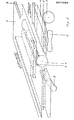
- 1 denotes a ball core and 2, 3 dumbbell-shaped covering parts, which are to be applied in an interlocking manner at an angle of 90 ° by rolling the glued ball core over the dumbbell-shaped cover parts laid out on the ball core 1.
- Fig. 1 of the drawing only one dumbbell-shaped cover part 2, 3 is shown schematically. It can therefore be assumed that a cover part magazine is provided instead of the individually shown dumbbell-shaped cover parts.
- a first pressure device in the form of a slide 4, which is located one above the other Magazine of the cover parts 2 or the corresponding table opening extending spherically curved pressure and guide channel 5 and can be moved back and forth in the direction of the longitudinal axis of the cover part magazine opening. This direction is defined in the drawing as "1st direction of movement”.
- a further slide 6 is also provided with a guide and pressure channel 7, which can be moved back and forth in a direction offset by 90 ° with respect to the slide 4, the guide channel extending in the longitudinal direction over the magazine of the cover parts 3 extends.
- either the first carriage 4 can be guided in the carriage 6 and this in turn can be guided in a table-fixed guide 8, but both carriages can also be guided separately in a table-fixed guide.
- Fig. 2 of the drawing in the rest of the corresponding parts with the same reference numerals as in Fig. 1, 9 denotes a conveyor belt, which is provided with downwardly open trays 10 and with the help of the ball cores 1 individually be brought into the area of the first carriage 4.
- a lifting plate 11 is located under the conveyor belt in the area of the slide 4, with the aid of which the ball core 1 can be lifted by reaching through the open shell 10 and brought into contact with the slide 4 or the guide channel 5.
- the work table of the device is shown at 12, in which there is an opening 13 corresponding to the contour of the cover parts, under which in turn a magazine carrier 14 is arranged.
- the magazine carrier can be lifted in cycles by one cover part thickness in such a way that the cover part 2 lying at the top of the magazine is in the plane of the work table.
- the lifting device used is a lifting plate 14 with two link belts 15 guiding the magazine on opposite side surfaces, but instead of which any other suitable lifting and guiding device can be provided.
- the ball core is first transported into the area of the slide 4 with the aid of the conveyor belt 9 and raised so far by means of the lifting plate 11 that the ball core comes into contact with the guide channel 5. Then the carriage 4 - see FIG. 1 - is moved in the first direction of movement, the ball core 1 being rolled on the work table over the cover part magazine 2, from which it removes the top cover part by gluing due to its surface gluing. By appropriate advancement of the carriage 4, the now partially occupied ball core is released from the carriage 4 and reaches the region of the guide channel 7, from which it is gripped and rolled over the second cover part magazine 3 by movement of the carriage 6 in the second direction of movement from which he removes the top cover part with gluing in the same way.
- the movement distances and track spacings are coordinated with one another in such a way that the two dumbbell-shaped cover parts are applied in an interlocking manner at an angle of 90 ° and the loop seam typical for balls thus occupied is formed.
- the occupancy process is now complete and the sledges are returned to their starting position for taking over and occupying the next ball core.
- a loading table 12 is also provided with recesses 13 corresponding to the shape of the cover parts 2, under each of which there is a lifting device for the cyclical lifting of a cover part magazine by one cover part thickness is arranged.
- the pressure device consists of a link belt 16 or 17 with grooved links which complement one another to form a guide track for the ball core and which extend parallel to the link belt by means of a distance which extends transversely to the link belt 16 of the first covering track and at a distance corresponding to the ball thickness of the second document track reaching conveyor belt 19 are connected to one another, the speeds of the conveyor belt 19 and the link belt 17 of the second document track being matched to one another such that the partially occupied ball core due to the due to the two different speeds of rotation resulting movement until reaching the magazine of the second document web makes a rotation of about 270 ° forwards or 90 ° backwards in such a way that the front edge of the cover part adjoins the bay edge of the cover part already applied with a visible seam distance.
- the balls can be continuously occupied in a short time cycle and without interruption because the device must be returned to the zero position.
Landscapes
- Engineering & Computer Science (AREA)
- Mechanical Engineering (AREA)
- Manufacturing & Machinery (AREA)
- Delivering By Means Of Belts And Rollers (AREA)
- Adhesives Or Adhesive Processes (AREA)
- Automatic Assembly (AREA)
Applications Claiming Priority (4)
| Application Number | Priority Date | Filing Date | Title |
|---|---|---|---|
| DE3142065 | 1981-10-23 | ||
| DE3142065 | 1981-10-23 | ||
| DE3228341 | 1982-07-29 | ||
| DE3228341A DE3228341A1 (de) | 1981-10-23 | 1982-07-29 | Verfahren zum belegen von spielbaellen mit deckteilen |
Publications (2)
| Publication Number | Publication Date |
|---|---|
| EP0077990A1 true EP0077990A1 (fr) | 1983-05-04 |
| EP0077990B1 EP0077990B1 (fr) | 1989-03-15 |
Family
ID=25796846
Family Applications (1)
| Application Number | Title | Priority Date | Filing Date |
|---|---|---|---|
| EP82109584A Expired EP0077990B1 (fr) | 1981-10-23 | 1982-10-16 | Procédé pour l'application des pièces d'enveloppe sur des balles de jeu |
Country Status (3)
| Country | Link |
|---|---|
| US (1) | US4543143A (fr) |
| EP (1) | EP0077990B1 (fr) |
| DE (1) | DE3228341A1 (fr) |
Families Citing this family (2)
| Publication number | Priority date | Publication date | Assignee | Title |
|---|---|---|---|---|
| DE3511882A1 (de) * | 1985-04-01 | 1986-10-09 | Stefan Dipl.-Ing. 5210 Troisdorf Siebertz | Verfahren zur belegung von tennisbaellen |
| ITMI20071389A1 (it) * | 2007-07-12 | 2009-01-13 | System Plast Spa | Sistema di mini convogliatori |
Citations (3)
| Publication number | Priority date | Publication date | Assignee | Title |
|---|---|---|---|---|
| US2509528A (en) * | 1947-01-30 | 1950-05-30 | Roberts Robert Eldon | Apparatus for covering balls |
| GB642469A (en) * | 1947-03-05 | 1950-09-06 | Fred Thomas Roberts | Improved method and apparatus for covering balls |
| FR2128830A1 (fr) * | 1971-03-12 | 1972-10-20 | Dunlop Holdings Ltd |
Family Cites Families (10)
| Publication number | Priority date | Publication date | Assignee | Title |
|---|---|---|---|---|
| US1117129A (en) * | 1911-07-14 | 1914-11-10 | Package Machinery Co | Wrapping-machine. |
| US1048092A (en) * | 1911-12-18 | 1912-12-24 | Frederick H Perry | Method of making base-balls. |
| US1117130A (en) * | 1914-03-05 | 1914-11-10 | Package Machinery Co | Wrapping-machine. |
| US1435680A (en) * | 1918-11-30 | 1922-11-14 | Allan A Adamson | Round-package-labeling machine |
| US1706384A (en) * | 1928-03-29 | 1929-03-19 | Pennsylvania Rubber Company | Tennis-ball-covering machine |
| US2045287A (en) * | 1935-05-17 | 1936-06-23 | M J B Company | Attachment for can labeling machines |
| US2299544A (en) * | 1939-05-09 | 1942-10-20 | Walter E Humphrey | Process and apparatus for covering balls |
| US3690435A (en) * | 1970-04-16 | 1972-09-12 | John W King | Article conveyor system |
| US4194941A (en) * | 1974-07-22 | 1980-03-25 | Fmc Corporation | Labelling machine |
| US4017003A (en) * | 1975-12-18 | 1977-04-12 | The Lakso Company, Incorporated | Article dispensing machine |
-
1982
- 1982-07-29 DE DE3228341A patent/DE3228341A1/de not_active Withdrawn
- 1982-10-16 EP EP82109584A patent/EP0077990B1/fr not_active Expired
-
1984
- 1984-10-29 US US06/666,121 patent/US4543143A/en not_active Expired - Lifetime
Patent Citations (3)
| Publication number | Priority date | Publication date | Assignee | Title |
|---|---|---|---|---|
| US2509528A (en) * | 1947-01-30 | 1950-05-30 | Roberts Robert Eldon | Apparatus for covering balls |
| GB642469A (en) * | 1947-03-05 | 1950-09-06 | Fred Thomas Roberts | Improved method and apparatus for covering balls |
| FR2128830A1 (fr) * | 1971-03-12 | 1972-10-20 | Dunlop Holdings Ltd |
Also Published As
| Publication number | Publication date |
|---|---|
| EP0077990B1 (fr) | 1989-03-15 |
| DE3228341A1 (de) | 1983-05-05 |
| US4543143A (en) | 1985-09-24 |
Similar Documents
| Publication | Publication Date | Title |
|---|---|---|
| DE4107224C1 (fr) | ||
| CH403811A (de) | Verfahren und Vorrichtung zum Einbringen von Einlagen in gefalzte Umschlagbogen | |
| EP0909728A1 (fr) | Dispositif et procédé de décoration d'objets | |
| DE3222657A1 (de) | Einrichtung und verfahren zum automatischen montieren von teilen auf chassis | |
| DE69422661T2 (de) | Verfahren und Vorrichtung zum Einwickeln von Gegenständen | |
| DE3042519A1 (de) | Vorrichtung zum stapeln von produkten | |
| DE2365901C3 (de) | Vorrichtung zum Ausrichten von Birnen | |
| DE2649638C2 (de) | Vorrichtung zum Bearbeiten des oberen Randes an einem offenen Behälter | |
| DE2800846C3 (de) | Vorrichtung zum Aufbringen von Abschlußblättern o.dgl. auf Blattlagen | |
| EP0006505B1 (fr) | Dispositif d'étiquetage d'articles plats tels que des minicassettes, des cassettes video ou similaires | |
| DE4224522C1 (de) | Verfahren und Pressenanlage zur Herstellung plattenförmiger, beidseitig mit Furnier versehener Werkstücke | |
| DE3726726A1 (de) | Leiterplatten-wechselvorrichtung | |
| EP0077990B1 (fr) | Procédé pour l'application des pièces d'enveloppe sur des balles de jeu | |
| DE3505597C2 (de) | Vorrichtung zum Bilden von mit Abstand aufeinanderfolgenden, quer zur Transportrichtung ausgerichteten Querreihen von gefüllten Waffelschnitten | |
| EP1318958A1 (fr) | Procede et dispositif d'apport d'objets reguliers a une station de travail | |
| DE3704050C2 (de) | Blattförderer | |
| DE2942748C2 (de) | Fördervorrichtung zum ein- oder mehrmaligen Durchstoßlackieren von einem Magazin entnehmbaren stab- oder hülsenförmigen Werkstücken | |
| DE2150021C3 (de) | Anlegevorrichtung | |
| DE2365779B2 (de) | Vorrichtung zum Ausrichten von Dosen | |
| DE4205197C2 (de) | Vorrichtung zum Einfüllen von Füllgut in eine Hülle, insbesondere einen Briefumschlag | |
| DD215269A1 (de) | Vorrichtung zur speicherung kompletter werkzeugmagazine an automatischen werkzeugmaschinen | |
| DE10355391A1 (de) | Transportvorrichtung und -verfahren für Tabakballen und -gebinde | |
| EP3951039B1 (fr) | Dispositif d'alimentation pour machines à coudre destiné au chargement automatique d'une machine à coudre en pièce à coudre | |
| DE3137241A1 (de) | Verfahren und vorrichtung zum einkleben von stoffmuster-proben in kataloge | |
| DE1299278B (de) | Vorrichtung zum serienmaessigen Zusammentragen bedruckter Einzelblaetter und Kohlepapiere zu Formularsaetzen, Durchschreibeblocks u. dgl. |
Legal Events
| Date | Code | Title | Description |
|---|---|---|---|
| PUAI | Public reference made under article 153(3) epc to a published international application that has entered the european phase |
Free format text: ORIGINAL CODE: 0009012 |
|
| AK | Designated contracting states |
Designated state(s): FR GB IT SE |
|
| 17P | Request for examination filed |
Effective date: 19831018 |
|
| GRAA | (expected) grant |
Free format text: ORIGINAL CODE: 0009210 |
|
| AK | Designated contracting states |
Kind code of ref document: B1 Designated state(s): FR GB IT SE |
|
| ITF | It: translation for a ep patent filed | ||
| ET | Fr: translation filed | ||
| GBT | Gb: translation of ep patent filed (gb section 77(6)(a)/1977) | ||
| PGFP | Annual fee paid to national office [announced via postgrant information from national office to epo] |
Ref country code: SE Payment date: 19890929 Year of fee payment: 8 |
|
| ITTA | It: last paid annual fee | ||
| PLBE | No opposition filed within time limit |
Free format text: ORIGINAL CODE: 0009261 |
|
| STAA | Information on the status of an ep patent application or granted ep patent |
Free format text: STATUS: NO OPPOSITION FILED WITHIN TIME LIMIT |
|
| 26N | No opposition filed | ||
| PG25 | Lapsed in a contracting state [announced via postgrant information from national office to epo] |
Ref country code: SE Effective date: 19901017 |
|
| PGFP | Annual fee paid to national office [announced via postgrant information from national office to epo] |
Ref country code: GB Payment date: 19920923 Year of fee payment: 11 |
|
| PGFP | Annual fee paid to national office [announced via postgrant information from national office to epo] |
Ref country code: FR Payment date: 19921030 Year of fee payment: 11 |
|
| PG25 | Lapsed in a contracting state [announced via postgrant information from national office to epo] |
Ref country code: GB Effective date: 19931016 |
|
| GBPC | Gb: european patent ceased through non-payment of renewal fee |
Effective date: 19931016 |
|
| PG25 | Lapsed in a contracting state [announced via postgrant information from national office to epo] |
Ref country code: FR Effective date: 19940630 |
|
| REG | Reference to a national code |
Ref country code: FR Ref legal event code: ST |
|
| EUG | Se: european patent has lapsed |
Ref document number: 82109584.1 Effective date: 19910603 |