EP0078134A1 - Lagerungsbehälter - Google Patents
Lagerungsbehälter Download PDFInfo
- Publication number
- EP0078134A1 EP0078134A1 EP82305486A EP82305486A EP0078134A1 EP 0078134 A1 EP0078134 A1 EP 0078134A1 EP 82305486 A EP82305486 A EP 82305486A EP 82305486 A EP82305486 A EP 82305486A EP 0078134 A1 EP0078134 A1 EP 0078134A1
- Authority
- EP
- European Patent Office
- Prior art keywords
- base
- inner container
- tank
- container
- wall
- Prior art date
- Legal status (The legal status is an assumption and is not a legal conclusion. Google has not performed a legal analysis and makes no representation as to the accuracy of the status listed.)
- Withdrawn
Links
- 238000009413 insulation Methods 0.000 claims abstract description 30
- 239000007788 liquid Substances 0.000 claims abstract description 21
- 230000004888 barrier function Effects 0.000 abstract description 41
- 230000035515 penetration Effects 0.000 abstract description 3
- 229910000831 Steel Inorganic materials 0.000 description 10
- 239000010959 steel Substances 0.000 description 10
- 239000011521 glass Substances 0.000 description 4
- 239000000463 material Substances 0.000 description 4
- 238000010276 construction Methods 0.000 description 3
- 230000002093 peripheral effect Effects 0.000 description 3
- 238000011109 contamination Methods 0.000 description 2
- 238000010438 heat treatment Methods 0.000 description 2
- 239000012774 insulation material Substances 0.000 description 2
- 230000004048 modification Effects 0.000 description 2
- 238000012986 modification Methods 0.000 description 2
- 239000000047 product Substances 0.000 description 2
- 239000004576 sand Substances 0.000 description 2
- 238000007789 sealing Methods 0.000 description 2
- 229910000975 Carbon steel Inorganic materials 0.000 description 1
- 239000010962 carbon steel Substances 0.000 description 1
- 230000001413 cellular effect Effects 0.000 description 1
- 239000006260 foam Substances 0.000 description 1
- 230000008014 freezing Effects 0.000 description 1
- 238000007710 freezing Methods 0.000 description 1
- 230000002706 hydrostatic effect Effects 0.000 description 1
- 239000002184 metal Substances 0.000 description 1
- 235000019362 perlite Nutrition 0.000 description 1
- 239000010451 perlite Substances 0.000 description 1
- 239000012466 permeate Substances 0.000 description 1
- 230000000717 retained effect Effects 0.000 description 1
- 238000009738 saturating Methods 0.000 description 1
- 210000002435 tendon Anatomy 0.000 description 1
- 230000007704 transition Effects 0.000 description 1
- 238000003466 welding Methods 0.000 description 1
Images



Classifications
-
- F—MECHANICAL ENGINEERING; LIGHTING; HEATING; WEAPONS; BLASTING
- F17—STORING OR DISTRIBUTING GASES OR LIQUIDS
- F17C—VESSELS FOR CONTAINING OR STORING COMPRESSED, LIQUEFIED OR SOLIDIFIED GASES; FIXED-CAPACITY GAS-HOLDERS; FILLING VESSELS WITH, OR DISCHARGING FROM VESSELS, COMPRESSED, LIQUEFIED, OR SOLIDIFIED GASES
- F17C13/00—Details of vessels or of the filling or discharging of vessels
- F17C13/12—Arrangements or mounting of devices for preventing or minimising the effect of explosion ; Other safety measures
- F17C13/126—Arrangements or mounting of devices for preventing or minimising the effect of explosion ; Other safety measures for large storage containers for liquefied gas
-
- F—MECHANICAL ENGINEERING; LIGHTING; HEATING; WEAPONS; BLASTING
- F17—STORING OR DISTRIBUTING GASES OR LIQUIDS
- F17C—VESSELS FOR CONTAINING OR STORING COMPRESSED, LIQUEFIED OR SOLIDIFIED GASES; FIXED-CAPACITY GAS-HOLDERS; FILLING VESSELS WITH, OR DISCHARGING FROM VESSELS, COMPRESSED, LIQUEFIED, OR SOLIDIFIED GASES
- F17C3/00—Vessels not under pressure
- F17C3/02—Vessels not under pressure with provision for thermal insulation
- F17C3/022—Land-based bulk storage containers
-
- F—MECHANICAL ENGINEERING; LIGHTING; HEATING; WEAPONS; BLASTING
- F17—STORING OR DISTRIBUTING GASES OR LIQUIDS
- F17C—VESSELS FOR CONTAINING OR STORING COMPRESSED, LIQUEFIED OR SOLIDIFIED GASES; FIXED-CAPACITY GAS-HOLDERS; FILLING VESSELS WITH, OR DISCHARGING FROM VESSELS, COMPRESSED, LIQUEFIED, OR SOLIDIFIED GASES
- F17C2203/00—Vessel construction, in particular walls or details thereof
- F17C2203/06—Materials for walls or layers thereof; Properties or structures of walls or their materials
- F17C2203/0634—Materials for walls or layers thereof
- F17C2203/0678—Concrete
Definitions
- tanks of the kind described Such tanks will be referred to hereinafter as "tanks of the kind described”.
- a tank of the kind described comprising continuous skirt means extending downwardly withrespect to and in the region of the periphery of the base of the inner container, and continuous flange means extending upwardly from the base of the outer container and radially within the skirt means, the free edge of the skirt means being lower than the free edge of the flange means to provide a vapour lock between the base insulation and the space between the inner and outer walls of the tank in the event of a leak from the wall of the inner container to limit the amount of liquid reaching the base insulation.
- the tank may be cylindrical and the skirt means and flange means annular.
- the skirt means may be of a diameter greater than the diameter of the inner container.
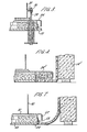
- a bedding layer 23 of sand Beneath the inner container base 12 is a bedding layer 23 of sand and beneath the bedding layer of sand 23 is a barrier sheet 24 of steel having a skirt 25 extending downwardly and continuously around the periphery of the barrier sheet 24.
- a base insulation layer 26' of foamed glass in block form, or other suitable insulation material surrounded by a'ring of lightweight insulating concrete blocks 26 and, radially inwardly of the skirt 25, a flange 27 extends continuously and upwardly from the vapour barrier 15.
- the vapour barrier 15 and the flange 27 are conveniently of steel so that the flange 27 can be secured to the vapour barrier by welding although other means may be used.
- the flange 27 extends above the base of the skirt 25 with the result that, if a leak occurs in the wall 11 of the inner container causing liquid to occupy the space between the wall 11 and the vapour barrier 15, when liquid begins to permeate the base insulation it is warmed and produces a vapour pressure which causes the combination of the skirt 25 and flange 27 to act as a vapour lock to prevent further entry of liquid from the space between the wall 11 and the vapour barrier 15 into the base insulation. In this way, wide spread contamination of the base insulation by the liquid is prevented.
- a layer 28 of wall foam insulation is provided on the inside of the vapour barrier 15.
- a further advantage of the vapour lock arrangement is that since the liquid level in the inner container would always be greater or equal to the liquid in the annular space between the wall 11 and the vapour barrier 15, there would be no danger of vapour pressure in the base insulation lifting the inner container base 12. The vapour pressure beneath the barrier 24 cannot exceed the pressure caused by liquid contained in the inner container 11.
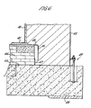
- Figure 3 shows a bracket arrangement for securing the inner container to the foundations.
- a bolt 29 is set in the foundations and passes through the vapour barrier 15 and the barrier sheet 24, sealing welds being made between the bolt 29 and the vapour barrier and barrier sheet.
- a nut 30 applies pressure to a flange 31 secured to the inner container to hold down the inner container for example to resist forces from events such as earthquakes.
- Figure 4 illustrates a base edge detail of a modified tank of the type shown in Figures 1, 2 and 3.
- barrier sheet 24 1 extending further out beyond the periphery of the inner container than was the case in the embodiment of Figures 1 to 3 and the liquid barrier is extended close to outer containment wall 14. This arrangement reduces the area over the base slab that cold temperatures could apply and could ease design on the concrete beneath the outer containment wall 14 .
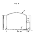
- FIG. 8 A further embodiment of a tank, generally indicated at 60, is shown in Figure 8.
- the tank 60 has an inner container 61 conveniently of steel with a dome roof.
- An insulation layer 62 covers the wall and roof of the inner container 61.
- the inner container 61 is seated, in a similar way to the embodiment of Figure 3, on a base insulation layer 63, suitably of foamed glass with a barrier 64 of steel or other suitable material between the base insulation 63 and the base of inner container 61.
- the barrier 64 has a downturned peripheral skirt 65 and a flange 66 extends from outer base 67, the skirt 65 and flange 66 providing a vapour lock in the way hereinbefore described.
- a bund wall 68 extends around the outside of the inner container 61 to prevent widespread liquid spillage in the event of a leak.
Landscapes
- Engineering & Computer Science (AREA)
- Mechanical Engineering (AREA)
- General Engineering & Computer Science (AREA)
- Physics & Mathematics (AREA)
- Thermal Sciences (AREA)
- Filling Or Discharging Of Gas Storage Vessels (AREA)
Applications Claiming Priority (2)
| Application Number | Priority Date | Filing Date | Title |
|---|---|---|---|
| GB08132392A GB2108647B (en) | 1981-10-27 | 1981-10-27 | Improvements in tanks |
| GB8132392 | 1981-10-27 |
Publications (1)
| Publication Number | Publication Date |
|---|---|
| EP0078134A1 true EP0078134A1 (de) | 1983-05-04 |
Family
ID=10525430
Family Applications (1)
| Application Number | Title | Priority Date | Filing Date |
|---|---|---|---|
| EP82305486A Withdrawn EP0078134A1 (de) | 1981-10-27 | 1982-10-14 | Lagerungsbehälter |
Country Status (2)
| Country | Link |
|---|---|
| EP (1) | EP0078134A1 (de) |
| GB (1) | GB2108647B (de) |
Cited By (4)
| Publication number | Priority date | Publication date | Assignee | Title |
|---|---|---|---|---|
| EP0915284A1 (de) * | 1997-01-31 | 1999-05-12 | KAEFER Isoliertechnik GmbH & Co. KG | Wärmedämmung für einen Kugeltank |
| WO2010098673A1 (en) * | 2009-02-27 | 2010-09-02 | Sevan Marine Asa | Flexible lower tank |
| WO2020052811A1 (de) * | 2018-09-11 | 2020-03-19 | Linde Aktiengesellschaft | Tank |
| WO2020052810A1 (de) * | 2018-09-11 | 2020-03-19 | Linde Aktiengesellschaft | Tank |
Citations (4)
| Publication number | Priority date | Publication date | Assignee | Title |
|---|---|---|---|---|
| FR1135932A (fr) * | 1955-04-06 | 1957-05-06 | Union Stock Yard & Transit Co Chicago | Réservoir isolant |
| US3208621A (en) * | 1963-08-16 | 1965-09-28 | North American Aviation Inc | Insulated tank for liquids boiling below ambient temperatures |
| GB2005397A (en) * | 1977-10-07 | 1979-04-19 | Shell Int Research | Containers for liquefied gas |
| GB2058320A (en) * | 1979-09-08 | 1981-04-08 | Dyckerhoff & Widmann Ag | Double-walled tanks for low temperature liquids |
-
1981
- 1981-10-27 GB GB08132392A patent/GB2108647B/en not_active Expired
-
1982
- 1982-10-14 EP EP82305486A patent/EP0078134A1/de not_active Withdrawn
Patent Citations (4)
| Publication number | Priority date | Publication date | Assignee | Title |
|---|---|---|---|---|
| FR1135932A (fr) * | 1955-04-06 | 1957-05-06 | Union Stock Yard & Transit Co Chicago | Réservoir isolant |
| US3208621A (en) * | 1963-08-16 | 1965-09-28 | North American Aviation Inc | Insulated tank for liquids boiling below ambient temperatures |
| GB2005397A (en) * | 1977-10-07 | 1979-04-19 | Shell Int Research | Containers for liquefied gas |
| GB2058320A (en) * | 1979-09-08 | 1981-04-08 | Dyckerhoff & Widmann Ag | Double-walled tanks for low temperature liquids |
Cited By (6)
| Publication number | Priority date | Publication date | Assignee | Title |
|---|---|---|---|---|
| EP0915284A1 (de) * | 1997-01-31 | 1999-05-12 | KAEFER Isoliertechnik GmbH & Co. KG | Wärmedämmung für einen Kugeltank |
| WO2010098673A1 (en) * | 2009-02-27 | 2010-09-02 | Sevan Marine Asa | Flexible lower tank |
| CN102325690A (zh) * | 2009-02-27 | 2012-01-18 | 塞万海洋股份有限公司 | 具有柔韧下部的储罐 |
| CN102325690B (zh) * | 2009-02-27 | 2014-10-15 | 塞万海洋股份有限公司 | 具有柔韧下部的储罐 |
| WO2020052811A1 (de) * | 2018-09-11 | 2020-03-19 | Linde Aktiengesellschaft | Tank |
| WO2020052810A1 (de) * | 2018-09-11 | 2020-03-19 | Linde Aktiengesellschaft | Tank |
Also Published As
| Publication number | Publication date |
|---|---|
| GB2108647A (en) | 1983-05-18 |
| GB2108647B (en) | 1985-06-12 |
Similar Documents
| Publication | Publication Date | Title |
|---|---|---|
| US4366654A (en) | Double-walled tank for low-temperature liquids | |
| US4041722A (en) | Impact resistant tank for cryogenic fluids | |
| US8020721B2 (en) | Tank for storing cryogenic fluids and method for constructing a fluid tight tank | |
| CA1045061A (en) | Insulated tank | |
| US4315385A (en) | High-safety container | |
| GB2058320A (en) | Double-walled tanks for low temperature liquids | |
| US3481504A (en) | Liquid storage container | |
| US3326011A (en) | Cryogenic storage facility | |
| EP0078134A1 (de) | Lagerungsbehälter | |
| US2954892A (en) | Vessel for storing cold liquids | |
| US3882809A (en) | Storage vessel for ship transport of liquefied gas | |
| JPH0610519B2 (ja) | 三重殻貯液槽 | |
| US3025993A (en) | Anchor system | |
| US3416325A (en) | Low temperature storage tank | |
| US3225955A (en) | Land storage for liquefied gases | |
| US4128187A (en) | Secondary barrier construction for low temperature liquified gas storage tank carrying vessels | |
| US3562986A (en) | Liquid storage container | |
| US3687149A (en) | Depressuring system for relieving tank anchor bolt load in case of fire | |
| US4074485A (en) | Safety wall for a storage tank | |
| JPH0123919Y2 (de) | ||
| JPS6126720Y2 (de) | ||
| JPH0338560Y2 (de) | ||
| JPH09165090A (ja) | 低温貯槽 | |
| JP2640725B2 (ja) | 地上式lngタンクのタンク構造 | |
| KR790001832B1 (ko) | 독립된 압력 화물탱크를 갖는 개량식 선박 |
Legal Events
| Date | Code | Title | Description |
|---|---|---|---|
| PUAI | Public reference made under article 153(3) epc to a published international application that has entered the european phase |
Free format text: ORIGINAL CODE: 0009012 |
|
| AK | Designated contracting states |
Designated state(s): DE FR IT NL |
|
| 17P | Request for examination filed |
Effective date: 19830426 |
|
| STAA | Information on the status of an ep patent application or granted ep patent |
Free format text: STATUS: THE APPLICATION IS DEEMED TO BE WITHDRAWN |
|
| 18D | Application deemed to be withdrawn |
Effective date: 19841009 |
|
| RIN1 | Information on inventor provided before grant (corrected) |
Inventor name: DIXON, JOHN MALCOLM |