EP0078564B1 - Câble de précontrainte pour structures de béton et structures de béton comprenant un tel câble - Google Patents
Câble de précontrainte pour structures de béton et structures de béton comprenant un tel câble Download PDFInfo
- Publication number
- EP0078564B1 EP0078564B1 EP82201303A EP82201303A EP0078564B1 EP 0078564 B1 EP0078564 B1 EP 0078564B1 EP 82201303 A EP82201303 A EP 82201303A EP 82201303 A EP82201303 A EP 82201303A EP 0078564 B1 EP0078564 B1 EP 0078564B1
- Authority
- EP
- European Patent Office
- Prior art keywords
- core wire
- wire
- strand
- treatment
- outer wires
- Prior art date
- Legal status (The legal status is an assumption and is not a legal conclusion. Google has not performed a legal analysis and makes no representation as to the accuracy of the status listed.)
- Expired
Links
- 239000004567 concrete Substances 0.000 title claims abstract description 18
- 238000011282 treatment Methods 0.000 claims abstract description 21
- 238000000151 deposition Methods 0.000 claims abstract description 5
- 239000011248 coating agent Substances 0.000 claims abstract description 4
- 238000000576 coating method Methods 0.000 claims abstract description 4
- 230000008021 deposition Effects 0.000 claims abstract description 3
- 238000005530 etching Methods 0.000 claims abstract description 3
- 238000007373 indentation Methods 0.000 claims abstract 2
- 238000000034 method Methods 0.000 claims description 17
- 238000004519 manufacturing process Methods 0.000 claims description 9
- 239000000843 powder Substances 0.000 claims description 4
- 238000003486 chemical etching Methods 0.000 claims description 3
- 238000010438 heat treatment Methods 0.000 claims description 3
- 239000011347 resin Substances 0.000 claims description 3
- 229920005989 resin Polymers 0.000 claims description 3
- 239000000126 substance Substances 0.000 claims description 3
- 230000001590 oxidative effect Effects 0.000 claims 2
- 238000012986 modification Methods 0.000 abstract description 2
- 230000004048 modification Effects 0.000 abstract description 2
- 230000003750 conditioning effect Effects 0.000 abstract 1
- 230000003647 oxidation Effects 0.000 abstract 1
- 238000007254 oxidation reaction Methods 0.000 abstract 1
- 239000000463 material Substances 0.000 description 6
- 238000012360 testing method Methods 0.000 description 5
- 238000004364 calculation method Methods 0.000 description 4
- 238000004873 anchoring Methods 0.000 description 3
- 238000010276 construction Methods 0.000 description 3
- 229910000831 Steel Inorganic materials 0.000 description 2
- 238000000227 grinding Methods 0.000 description 2
- 230000000704 physical effect Effects 0.000 description 2
- 239000010959 steel Substances 0.000 description 2
- 230000001419 dependent effect Effects 0.000 description 1
- 238000004836 empirical method Methods 0.000 description 1
- 238000005516 engineering process Methods 0.000 description 1
- 238000011835 investigation Methods 0.000 description 1
- 238000005259 measurement Methods 0.000 description 1
- 239000002245 particle Substances 0.000 description 1
- 239000011513 prestressed concrete Substances 0.000 description 1
- 230000003014 reinforcing effect Effects 0.000 description 1
- 238000007788 roughening Methods 0.000 description 1
- 229910010271 silicon carbide Inorganic materials 0.000 description 1
- 230000009897 systematic effect Effects 0.000 description 1
- 238000010998 test method Methods 0.000 description 1
Images
Classifications
-
- D—TEXTILES; PAPER
- D07—ROPES; CABLES OTHER THAN ELECTRIC
- D07B—ROPES OR CABLES IN GENERAL
- D07B1/00—Constructional features of ropes or cables
- D07B1/06—Ropes or cables built-up from metal wires, e.g. of section wires around a hemp core
- D07B1/0693—Ropes or cables built-up from metal wires, e.g. of section wires around a hemp core having a strand configuration
-
- D—TEXTILES; PAPER
- D07—ROPES; CABLES OTHER THAN ELECTRIC
- D07B—ROPES OR CABLES IN GENERAL
- D07B5/00—Making ropes or cables from special materials or of particular form
- D07B5/005—Making ropes or cables from special materials or of particular form characterised by their outer shape or surface properties
-
- E—FIXED CONSTRUCTIONS
- E04—BUILDING
- E04C—STRUCTURAL ELEMENTS; BUILDING MATERIALS
- E04C5/00—Reinforcing elements, e.g. for concrete; Auxiliary elements therefor
- E04C5/08—Members specially adapted to be used in prestressed constructions
-
- D—TEXTILES; PAPER
- D07—ROPES; CABLES OTHER THAN ELECTRIC
- D07B—ROPES OR CABLES IN GENERAL
- D07B2201/00—Ropes or cables
- D07B2201/20—Rope or cable components
- D07B2201/2047—Cores
- D07B2201/2052—Cores characterised by their structure
- D07B2201/2059—Cores characterised by their structure comprising wires
-
- D—TEXTILES; PAPER
- D07—ROPES; CABLES OTHER THAN ELECTRIC
- D07B—ROPES OR CABLES IN GENERAL
- D07B2201/00—Ropes or cables
- D07B2201/20—Rope or cable components
- D07B2201/2047—Cores
- D07B2201/2052—Cores characterised by their structure
- D07B2201/2065—Cores characterised by their structure comprising a coating
-
- D—TEXTILES; PAPER
- D07—ROPES; CABLES OTHER THAN ELECTRIC
- D07B—ROPES OR CABLES IN GENERAL
- D07B2401/00—Aspects related to the problem to be solved or advantage
- D07B2401/20—Aspects related to the problem to be solved or advantage related to ropes or cables
- D07B2401/205—Avoiding relative movement of components
-
- D—TEXTILES; PAPER
- D07—ROPES; CABLES OTHER THAN ELECTRIC
- D07B—ROPES OR CABLES IN GENERAL
- D07B2501/00—Application field
- D07B2501/20—Application field related to ropes or cables
- D07B2501/2015—Construction industries
- D07B2501/2023—Concrete enforcements
Definitions
- the invention relates to a prestressing strand for post-tensioning a concrete structure, having at least one central core wire and a plurality of outer wires extending helically around the said core wire so as to envelop the core wire.
- Such strands are often used as the tensioned reinforcing elements in prestressed concrete structures, in which they may for example be inserted in curved conduits in the concrete structure.
- the conduits are formed for example by tubes of steel or another material, which are pre-cast into the concrete structure.
- the invention also relates to a process of manufacturing such strand and to a concrete structure containing such strand.
- the core wire should be some 5 to 7% larger in diameter than the outer wires. According to Techniques de I' 1976 this slightly larger diameter of the core wire is necessary to ensure that movement of the core wire relative to the outer wires is possible during the tensioning of the strand.
- the invention arrived after extensive trials to a different insight with respect to the construction of the strand at the process of manufacturing such a strand, which will be explained in the following.
- the present invention arises because, for prestressing strand, investigations do not appear to have resulted in the most suitable practical strand construction for use in post-tensioning.
- the tension condition and the deformation condition of a prestressing strand in a curved configuration, in which the strand is subjected to transverse forces and frictional forces, is highly complex, and is dependent on a great number of factors which are related to the properties of the material and the production methods for the strand.
- the object of the present invention is therefore to make it possible to control and minimize variations in tension in prestressing strand in curved conduits.
- the inventors have realised that a considerably better consistency between the modulus of deformation and the modulus of elasticity can be obtained when the core wire can be more adequately tensioned over its whole length and can cooperate better as a load bearing element.
- One treatment method for the core is to form mechanically identations in the core wire surface.
- Another treatment method is to only modify the surface condition of the core wire so as to increase the coefficient of friction between the core wire and the outer wires.
- This frictional properties instead of accepting undesired variations in the frictional properties inside the strand, use is made of these frictional properties, by increasing this friction in order to reduce or even prevent any movement in longitudinal direction between the core wire and the outer wires.
- the surface condition of the wire can be adequately modified by subjecting it to a chemical etching treatment.
- Chemical etching treatments of steel products are generally known, which means that no further explanation needs to be given how such etching is to be performed in order to achieve a slight roughening of the surface, without unduly affecting the physical properties of the material.
- the object of the present invention may be obtained, without modifying the wire itself, if a resin coating in which an abrasive powder, e.g. a grinding powder such as carborundum, is admixed is applied to the wire.
- an abrasive powder e.g. a grinding powder such as carborundum
- the particles of the grinding power prevent or at least reduce movement between the various wires.
- wire treatment consists in depositing a friction-increasing substance upon the wire by an electrochemical or an electrostatic process.
- electrochemical or an electrostatic process there are many options available to the expert for achieving suitable deposition.
- the invention also relates to the process of manufacture of the prestressing strand and to a concrete structure containing one or more tensioned strands according to the invention, as described above.
- the manufacturing steps start from wire of surface condition hitherto conventional in this field, e.g. as supplied by wire manufacturers.
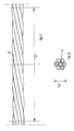
- Figs. 1 and 2 of the accompanying drawings show a prestressing strand having a single core wire b and six outer wires a in longitudinal view and in cross section respectively.
- Fig. 1 also indicates the pitch of the helices in which each of the outer wires lies. For the whole strand, this pitch S is referred to herein by the expression "helical pitch length”.
- Fig. 2 indicates the greatest cross sectional dimension which is herein called the maximum diameter of the strand. It is usual to express the helical pitch length as a multiple of the strand diameter. For prestressing strands, this length S generally lies between 12 and 18 times the diameter, although a value of S in this range is not essential for the present invention.
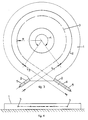
- Figs. 3 and 4 show a concrete plate 1 with a thickness of 22 cm. Through this plate 1 there extends a conduit 3 which over an angle of 5.07 radians is curved with a radius of curvature R of 100 cm. The length L 2 of the curved conduit part is consequently 507 cm. Across each end of the conduit 3 there is located a support beam 2 with at the left hand side a wedge anchoring 5 for a prestressing strand and at the right hand side a similar wedge anchoring 5 behind a hydraulic press 4 (schematically shown).
- the tensioned strand then consists of a straight section of length L, of 175 cm, a curved section of length L 2 of 507 cm and another straight section of length L 3 of 210 cm.
- Tests were carried out using the most common prestressing strand of thickness D of 0.5 inches, and having a core wire and six outer wires.
- the strand was brought under nominal tension, in order to stretch it sufficiently, whereupon the tension force was increased up to a value near the usual full load value used in tensioning technology. During the increase of the tension force, the elongation and the tension force in the strand were measured continuously.
- the strand was considered to be divided into elements, and for each element the stress and strain conditions were calculated with the application of a frictional force between the channel wall and the prestressing strand.
- frictional coefficients between the strand and the channel wall at various tension forces in the strand were determined. Per element, these friction coefficients were introduced into the calculation so that it was possible to determine by calculation, what tension forces should be present in the strand, on the basis of the total measured extension of the strand between the anchors 5. The value was compared with the actual tension forces obtained, from which a value could be obtained for the modulus of deformation in each test performed.
Landscapes
- Engineering & Computer Science (AREA)
- Architecture (AREA)
- Civil Engineering (AREA)
- Structural Engineering (AREA)
- Ropes Or Cables (AREA)
- Reinforcement Elements For Buildings (AREA)
- Curing Cements, Concrete, And Artificial Stone (AREA)
- Paper (AREA)
- Reinforced Plastic Materials (AREA)
- Investigation Of Foundation Soil And Reinforcement Of Foundation Soil By Compacting Or Drainage (AREA)
- Rod-Shaped Construction Members (AREA)
Claims (10)
Priority Applications (1)
| Application Number | Priority Date | Filing Date | Title |
|---|---|---|---|
| AT82201303T ATE28913T1 (de) | 1981-11-02 | 1982-10-20 | Vorspannkabel fuer betonkonstruktionen und betonkonstruktionen mit solchem kabel. |
Applications Claiming Priority (2)
| Application Number | Priority Date | Filing Date | Title |
|---|---|---|---|
| CH6966/81 | 1981-11-02 | ||
| CH696681 | 1981-11-02 |
Publications (3)
| Publication Number | Publication Date |
|---|---|
| EP0078564A2 EP0078564A2 (fr) | 1983-05-11 |
| EP0078564A3 EP0078564A3 (en) | 1984-05-23 |
| EP0078564B1 true EP0078564B1 (fr) | 1987-08-12 |
Family
ID=4317835
Family Applications (1)
| Application Number | Title | Priority Date | Filing Date |
|---|---|---|---|
| EP82201303A Expired EP0078564B1 (fr) | 1981-11-02 | 1982-10-20 | Câble de précontrainte pour structures de béton et structures de béton comprenant un tel câble |
Country Status (6)
| Country | Link |
|---|---|
| EP (1) | EP0078564B1 (fr) |
| AT (1) | ATE28913T1 (fr) |
| DE (1) | DE3276952D1 (fr) |
| ES (2) | ES516971A0 (fr) |
| FI (1) | FI72370C (fr) |
| NO (1) | NO165122C (fr) |
Families Citing this family (2)
| Publication number | Priority date | Publication date | Assignee | Title |
|---|---|---|---|---|
| CA1228998A (fr) * | 1982-10-28 | 1987-11-10 | Frederick F. Hunt | Cables d'acier a resistance a la corrosion et caracteristiques d'adherence ameliorees, destines surtout a la precontrainte du beton |
| JP5172028B1 (ja) * | 2012-04-12 | 2013-03-27 | 黒沢建設株式会社 | 二重防錆pc鋼より線 |
Family Cites Families (5)
| Publication number | Priority date | Publication date | Assignee | Title |
|---|---|---|---|---|
| US3131469A (en) * | 1960-03-21 | 1964-05-05 | Tyler Wayne Res Corp | Process of producing a unitary multiple wire strand |
| NL6506030A (fr) * | 1964-05-19 | 1965-11-22 | ||
| DE1525129C3 (de) * | 1965-01-02 | 1975-01-30 | Intercontinentale-Technik Gesellschaft Fuer Planung Und Konstruktion Mbh, 8000 Muenchen | Bündel aus hochfesten metallischen Längselementen |
| FR1586725A (fr) * | 1967-10-04 | 1970-02-27 | ||
| US3755003A (en) * | 1970-07-24 | 1973-08-28 | Diamond Shamrock Corp | Method of preparing and using concrete reinforcing elements |
-
1982
- 1982-10-20 AT AT82201303T patent/ATE28913T1/de not_active IP Right Cessation
- 1982-10-20 DE DE8282201303T patent/DE3276952D1/de not_active Expired
- 1982-10-20 EP EP82201303A patent/EP0078564B1/fr not_active Expired
- 1982-10-29 FI FI823701A patent/FI72370C/fi not_active IP Right Cessation
- 1982-10-29 ES ES516971A patent/ES516971A0/es active Granted
- 1982-11-01 NO NO823616A patent/NO165122C/no unknown
-
1983
- 1983-04-19 ES ES1983271531U patent/ES271531U/es active Pending
Non-Patent Citations (2)
| Title |
|---|
| HÜTTE, Bautechnik vol.1, page 726, * |
| Techniques de l'Ingénieur, pages C-360-5 and 6 * |
Also Published As
| Publication number | Publication date |
|---|---|
| DE3276952D1 (en) | 1987-09-17 |
| FI823701L (fi) | 1983-05-03 |
| NO165122B (no) | 1990-09-17 |
| FI72370B (fi) | 1987-01-30 |
| EP0078564A3 (en) | 1984-05-23 |
| ES271531U (es) | 1983-10-16 |
| EP0078564A2 (fr) | 1983-05-11 |
| ES8500372A1 (es) | 1984-10-01 |
| NO823616L (no) | 1983-05-03 |
| FI823701A0 (fi) | 1982-10-29 |
| ES516971A0 (es) | 1984-10-01 |
| FI72370C (fi) | 1987-05-11 |
| ATE28913T1 (de) | 1987-08-15 |
| NO165122C (no) | 1990-12-27 |
Similar Documents
| Publication | Publication Date | Title |
|---|---|---|
| JP3598125B2 (ja) | スチールコード | |
| EP0169588B1 (fr) | Structure de torsion pour câblé d'acier | |
| US3977174A (en) | Cable for reinforcing objects formed of elastic or easily deformable materials | |
| GB1582647A (en) | Metal cord | |
| AU9703401A (en) | Individually protected strand, its use in construction, and manufacturing process | |
| GB2034363A (en) | Metal cord | |
| EP0834662B1 (fr) | Ame pour commande à distance par câble | |
| US4608817A (en) | Single strand metal cord and method of making | |
| EP0078564B1 (fr) | Câble de précontrainte pour structures de béton et structures de béton comprenant un tel câble | |
| EP3760805A1 (fr) | Toron avec prise améliorée | |
| JP7327158B2 (ja) | 定着具 | |
| US5375404A (en) | Wide rope with reduced internal contact stresses | |
| US5307615A (en) | Flexible tension member | |
| WO2023074567A1 (fr) | Câble métallique | |
| JPH0331832B2 (fr) | ||
| EP0071292A1 (fr) | Câble de prétension pour structures de béton | |
| EP0040877A1 (fr) | Câblé métallique comportant des torons à filaments parallèles | |
| JPH11117456A (ja) | Pc鋼より線の定着部構造 | |
| RU2167968C2 (ru) | Витая проволочная структура | |
| JPH08144181A (ja) | スチールコードとゴムの複合体 | |
| EP0247130B1 (fr) | Toron pour structures en beton precontraint et son procede de fabrication | |
| JPH0791791B2 (ja) | ゴム製品補強用スチールコード | |
| KR100356313B1 (ko) | 이형 소선이 사용된 피씨 강연선 및 그 제조 장치 | |
| JPH08337980A (ja) | 高強度8ストランド型ワイヤロープ | |
| Costello | Testing of a Wire Rope |
Legal Events
| Date | Code | Title | Description |
|---|---|---|---|
| PUAI | Public reference made under article 153(3) epc to a published international application that has entered the european phase |
Free format text: ORIGINAL CODE: 0009012 |
|
| 17P | Request for examination filed |
Effective date: 19821020 |
|
| AK | Designated contracting states |
Designated state(s): AT BE CH DE FR GB LI SE |
|
| PUAL | Search report despatched |
Free format text: ORIGINAL CODE: 0009013 |
|
| AK | Designated contracting states |
Designated state(s): AT BE CH DE FR GB LI SE |
|
| GRAA | (expected) grant |
Free format text: ORIGINAL CODE: 0009210 |
|
| AK | Designated contracting states |
Kind code of ref document: B1 Designated state(s): AT BE CH DE FR GB LI SE |
|
| REF | Corresponds to: |
Ref document number: 28913 Country of ref document: AT Date of ref document: 19870815 Kind code of ref document: T |
|
| REF | Corresponds to: |
Ref document number: 3276952 Country of ref document: DE Date of ref document: 19870917 |
|
| ET | Fr: translation filed | ||
| PLBE | No opposition filed within time limit |
Free format text: ORIGINAL CODE: 0009261 |
|
| STAA | Information on the status of an ep patent application or granted ep patent |
Free format text: STATUS: NO OPPOSITION FILED WITHIN TIME LIMIT |
|
| 26N | No opposition filed | ||
| PGFP | Annual fee paid to national office [announced via postgrant information from national office to epo] |
Ref country code: FR Payment date: 19910911 Year of fee payment: 10 |
|
| PGFP | Annual fee paid to national office [announced via postgrant information from national office to epo] |
Ref country code: AT Payment date: 19910912 Year of fee payment: 10 |
|
| PGFP | Annual fee paid to national office [announced via postgrant information from national office to epo] |
Ref country code: GB Payment date: 19910913 Year of fee payment: 10 |
|
| PGFP | Annual fee paid to national office [announced via postgrant information from national office to epo] |
Ref country code: SE Payment date: 19910917 Year of fee payment: 10 Ref country code: CH Payment date: 19910917 Year of fee payment: 10 |
|
| PGFP | Annual fee paid to national office [announced via postgrant information from national office to epo] |
Ref country code: BE Payment date: 19910923 Year of fee payment: 10 |
|
| PGFP | Annual fee paid to national office [announced via postgrant information from national office to epo] |
Ref country code: DE Payment date: 19910930 Year of fee payment: 10 |
|
| PG25 | Lapsed in a contracting state [announced via postgrant information from national office to epo] |
Ref country code: GB Effective date: 19921020 Ref country code: AT Effective date: 19921020 |
|
| PG25 | Lapsed in a contracting state [announced via postgrant information from national office to epo] |
Ref country code: SE Effective date: 19921021 |
|
| PG25 | Lapsed in a contracting state [announced via postgrant information from national office to epo] |
Ref country code: LI Effective date: 19921031 Ref country code: CH Effective date: 19921031 Ref country code: BE Effective date: 19921031 |
|
| BERE | Be: lapsed |
Owner name: ESTEL NEDERLANDSE DRAADINDUSTRIE B.V. Effective date: 19921031 |
|
| GBPC | Gb: european patent ceased through non-payment of renewal fee |
Effective date: 19921020 |
|
| PG25 | Lapsed in a contracting state [announced via postgrant information from national office to epo] |
Ref country code: FR Effective date: 19930630 |
|
| REG | Reference to a national code |
Ref country code: CH Ref legal event code: PL |
|
| PG25 | Lapsed in a contracting state [announced via postgrant information from national office to epo] |
Ref country code: DE Effective date: 19930701 |
|
| REG | Reference to a national code |
Ref country code: FR Ref legal event code: ST |
|
| EUG | Se: european patent has lapsed |
Ref document number: 82201303.3 Effective date: 19930510 |