EP0078792B1 - Colonne d'incendie - Google Patents
Colonne d'incendie Download PDFInfo
- Publication number
- EP0078792B1 EP0078792B1 EP19820890162 EP82890162A EP0078792B1 EP 0078792 B1 EP0078792 B1 EP 0078792B1 EP 19820890162 EP19820890162 EP 19820890162 EP 82890162 A EP82890162 A EP 82890162A EP 0078792 B1 EP0078792 B1 EP 0078792B1
- Authority
- EP
- European Patent Office
- Prior art keywords
- mandrel
- valve
- hydrant
- pipe
- closing member
- Prior art date
- Legal status (The legal status is an assumption and is not a legal conclusion. Google has not performed a legal analysis and makes no representation as to the accuracy of the status listed.)
- Expired
Links
- 238000007789 sealing Methods 0.000 claims description 16
- 238000006073 displacement reaction Methods 0.000 claims description 3
- 239000011796 hollow space material Substances 0.000 claims 2
- XLYOFNOQVPJJNP-UHFFFAOYSA-N water Substances O XLYOFNOQVPJJNP-UHFFFAOYSA-N 0.000 description 19
- 238000010276 construction Methods 0.000 description 7
- 238000012423 maintenance Methods 0.000 description 3
- 238000011109 contamination Methods 0.000 description 2
- 230000000717 retained effect Effects 0.000 description 2
- 210000000078 claw Anatomy 0.000 description 1
- 239000000356 contaminant Substances 0.000 description 1
- 230000008014 freezing Effects 0.000 description 1
- 238000007710 freezing Methods 0.000 description 1
- 230000001771 impaired effect Effects 0.000 description 1
- 230000002093 peripheral effect Effects 0.000 description 1
- 239000010802 sludge Substances 0.000 description 1
Images


Classifications
-
- E—FIXED CONSTRUCTIONS
- E03—WATER SUPPLY; SEWERAGE
- E03B—INSTALLATIONS OR METHODS FOR OBTAINING, COLLECTING, OR DISTRIBUTING WATER
- E03B9/00—Methods or installations for drawing-off water
- E03B9/02—Hydrants; Arrangements of valves therein; Keys for hydrants
- E03B9/14—Draining devices for hydrants
Definitions
- the invention relates to an above-ground hydrant with a columnar housing, in which a valve which can be actuated with a valve spindle and a spindle nut is arranged at the lower end and which has an emptying opening which is open when the valve is closed, the end piece of the valve being connected to one in the Aligned axis of the hydrant, housing-fixed, hollow mandrel is slidably and near the lower end of the mandrel to the cavity of an outwardly leading channel is connected.
- the emptying openings of such known above-ground hydrants serve to drain off the water column remaining in the column-like housing after water has been removed from the hydrant, so that, in particular in the cold season, the hydrant is prevented from freezing up.
- the drain opening was arranged on the periphery of the columnar housing near the lower end thereof. The drain opening was ground when the end piece was lifted from the valve seat by a correspondingly large-sized sealing element and released again when the valve was closed.
- the invention aims to provide a surface hydrant, in which the closure of the drain opening is ensured for long periods of time without maintenance work even with heavily polluted water when the valve is open, and in which the drain opening is securely closed when the valve is opened.
- the invention consists in a above ground hydrant of the type specified essentially in that the end piece tightly encloses an outer smooth cylindrical portion of the mandrel and that the drain opening over the cavity of the mandrel formed by an axial bore and at least one of the valve seat lifted end piece closable radial opening opens into the space above the valve seat.
- the emptying opening opens via an axial bore of the mandrel and at least one radial opening into the space above the valve seat, central drainage of the water contained in the columnar housing after the valve is closed is achieved and the seal is limited to the peripheral surface of the mandrel , which area is at a distance above the lowest point of the hydrant, so that there is no risk of contamination by pollution.
- the seal can be formed by O-rings sliding on the circumference of the mandrel.
- the design can be such that the valve spindle is fixed in a manner known per se to be non-rotatable and axially immovable on the housing and is formed on the free end section of the mandrel and that the end piece is formed or connected to a sleeve sliding on the smooth cylindrical section of the mandrel , which in the open position of the valve sealingly engages over the radial opening (s) of the mandrel and releases it in the closed position of the valve.
- the safe closure of the emptying opening is ensured when the valve is opened by the sliding sleeve which, after opening the valve, sealingly engages over the openings for the axial bore.
- the training can also be made so that the hollow valve stem is rotatably mounted on the smoothly formed free end portion of the mandrel and that the spindle nut, or the end piece is formed or connected to a sliding sleeve on the cylindrical jacket of the mandrel, which in the Open position of the valve sealingly engages over the radial opening (s) of the mandrel and releases it in the closed position of the valve.
- the guide mandrel itself can be designed in a simple manner with a cylindrical jacket and the valve spindle can preferably be tubular and can be mounted on the guide mandrel.
- the sealing of the openings in the mandrel can be achieved in a particularly simple manner in that the sleeve near its two ends on its inner circumference sealing rings, in particular 0- Rings, wears.
- Such O-rings which only span the small diameter of the mandrel, ensure a long service life of the seal without the need for maintenance work.
- the design is such that the spindle nut or the end piece has at least one radial opening, which is in open connection with the openings of the mandrel in the closed position of the valve, in particular flush, resulting in a particularly simple construction of the entire locking mechanism for the valve .
- the spindle nut When the above-ground hydrant is designed with a tubular valve spindle, the spindle nut must be secured against rotation in order to ensure the stroke of the spindle nut, the anti-rotation device for the end piece and thus the sealing element also being essential for gentle treatment of the sealing body of the valve.
- This protection against rotation is preferably made so that the radial opening of the spindle nut or the end piece is designed as an elongated hole extending in the axial direction, in which engages a cross pin connected to the mandrel, resulting in a particularly simple construction. It is thus possible to avoid the claws on the inner circumference of the column-shaped housing, which are complex in terms of shape, as were provided in known constructions for the engagement of a part which is connected in a rotationally fixed manner to the valve body.
- the construction is expediently such that the tubular spindle carries a bush mounted on the mandrel, which at least on the side facing away from the valve the mandrel is secured against axial displacement by a locking member connected to the mandrel.
- the closing pressure of the valve is absorbed by the locking members on the mandrel and the rotatability of the tubular spindle is in no way impaired.
- Fig. 1 denotes the columnar housing of the hydrant, which is screwed to a hydrant head and a hydrant foot 3.
- Water outlet openings 4 are provided in the hydrant head 2 and can be locked by a cap 5.
- the hydrant head 2 is sealed off at the top by a cover plate 6, the cover plate 6 being connected to the hydrant head 2 in a sealing manner by means of screws 7.
- a cap 8 is rotatably mounted on the hydrant head 2 and is connected in a rotationally fixed manner to an actuating tube 9 by means of a screw 10. By turning the cap 8 and thus the tube 9, the valve is actuated.
- the actuating tube 9 is rotatably connected to a spindle nut 11 which meshes with a spindle thread of a mandrel 12 rigidly fixed in the hydrant foot 3.
- the spindle nut 11 By turning the spindle nut 11, the spindle nut is moved up and down in the axial direction of the mandrel 12.
- an end piece 13 With the spindle nut 11, an end piece 13 is axially immovably connected relative to the spindle nut and carries the sealing element 14 of the valve.
- the valve On the left side of FIG. 1, the valve is shown in the open state, whereas the right side of FIG. 1 shows the valve in the closed state.
- the pressurized water enters in the direction of arrow 15 and the pressurized water can be withdrawn via the water removal openings 4 when the valve is open.
- the spindle nut 11 can be moved downwards until the sealing element 16 lies sealingly against the valve seat.
- the water column remaining in the column-like housing 1 after closing the valve can now reach radial openings 18 on the circumference of the mandrel 12 via a radial opening 17 in the end piece 13. These radial openings 18 pass into an axial bore 19 of the mandrel 12, which opens at 20 into the drain channel 21.
- the radial openings 18 are arranged in a region of the mandrel 12 which has a smooth cylindrical outer surface.
- the end piece 13 is connected on its inside facing the mandrel 12 to a sealing sleeve 22, which carries at both ends on the periphery of the smooth cylindrical region of the mandrel 12 O-rings 23 which are guided in a sliding manner.
- this sleeve is moved together with the end piece 13 in the axial direction so far that the radial openings 18 of the dome 12 are released and are in open connection with the interior of the columnar housing 1 via the openings 17 in the end piece.
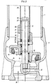
- FIG. 2 differs from the configuration according to FIG. 1 only in that the pressure water is supplied in the direction of arrow 24 from below.
- a vent valve 28 is provided in the cover plate 6, which ensures the unimpeded drainage of the water column after the valve is closed.
- a tubular rotatable spindle 29 which carries a bush 30 with an external thread at its lower end.
- the bushing 30 is mounted on a mandrel 31 which is axially immovably connected to the hydrant foot 3 and which has the radial openings 18 already designated in FIGS. 1 and 2 and the axial bore 19.
- the end piece 13 is formed in one piece with the spindle nut 11, which is in engagement with the thread of the sleeve 30. Upon rotation of the tubular spindle 29, the end piece 13 is moved up or down in the direction of the axis 32 of the mandrel 31.
- the end piece 13 again carries a sleeve 22 which is guided on the jacket of the mandrel 31 by the O-rings 23 in a sealing manner and is displaceable in the axial direction relative to the mandrel 31.
- the end piece 13 has an elongated hole 33 which extends in the axial direction and into which a pin 34 engages.
- the pin 34 passes through the mandrel 31 and a bearing ring 35, on which the sleeve 30 of the tubular spindle is supported downwards.
- the sleeve 30 in turn carries an O-ring 36, which prevents water from entering the interior of the tubular spindle 29.
- the closing forces of the valve are supported by the locking member 37 designed as a plate, which engages over the bush 30 and secures it against an axial movement upwards.
- the locking member 37 is connected to the mandrel 31 by a screw 38. 3, the reference numerals of FIGS. 1 and 2 have been retained for the same components.
Landscapes
- Health & Medical Sciences (AREA)
- Life Sciences & Earth Sciences (AREA)
- Engineering & Computer Science (AREA)
- Hydrology & Water Resources (AREA)
- Public Health (AREA)
- Water Supply & Treatment (AREA)
- Mechanically-Actuated Valves (AREA)
Claims (7)
Applications Claiming Priority (2)
| Application Number | Priority Date | Filing Date | Title |
|---|---|---|---|
| AT4726/81 | 1981-11-04 | ||
| AT472681A AT373001B (de) | 1981-11-04 | 1981-11-04 | Ueberflurhydrant |
Publications (2)
| Publication Number | Publication Date |
|---|---|
| EP0078792A1 EP0078792A1 (fr) | 1983-05-11 |
| EP0078792B1 true EP0078792B1 (fr) | 1985-05-29 |
Family
ID=3567609
Family Applications (1)
| Application Number | Title | Priority Date | Filing Date |
|---|---|---|---|
| EP19820890162 Expired EP0078792B1 (fr) | 1981-11-04 | 1982-11-03 | Colonne d'incendie |
Country Status (4)
| Country | Link |
|---|---|
| EP (1) | EP0078792B1 (fr) |
| AT (1) | AT373001B (fr) |
| DE (1) | DE3263926D1 (fr) |
| YU (1) | YU42603B (fr) |
Families Citing this family (4)
| Publication number | Priority date | Publication date | Assignee | Title |
|---|---|---|---|---|
| FR2721306B1 (fr) * | 1994-06-17 | 1996-08-09 | Pont A Mousson | Procédé et dispositif antipollution pour distribuer un fluide depuis un poste de distribution à plusieurs prises de branchement et utilisation. |
| DE102007060624B4 (de) * | 2007-12-15 | 2017-07-06 | Vag-Armaturen Gmbh | Hydrant |
| CN112982573B (zh) * | 2021-03-09 | 2024-05-24 | 列斯丽(深圳)技术有限公司 | 自排水式消火栓结构及包含它的消防井 |
| CN113137482B (zh) * | 2021-04-26 | 2023-04-07 | 陈晓东 | 一种具有防盗水功能的取水栓 |
Family Cites Families (3)
| Publication number | Priority date | Publication date | Assignee | Title |
|---|---|---|---|---|
| AT228721B (de) * | 1961-11-07 | 1963-08-12 | Franz Krammer | Hydrant, insbesondere Oberflurhydrant für Feuerlöschzwecke |
| AT330679B (de) * | 1974-03-25 | 1976-07-12 | Huebner Vamag | Uberflurhydrant |
| AT335923B (de) * | 1974-03-25 | 1977-04-12 | Huebner Vamag | Hydrant |
-
1981
- 1981-11-04 AT AT472681A patent/AT373001B/de not_active IP Right Cessation
-
1982
- 1982-11-03 EP EP19820890162 patent/EP0078792B1/fr not_active Expired
- 1982-11-03 YU YU246682A patent/YU42603B/xx unknown
- 1982-11-03 DE DE8282890162T patent/DE3263926D1/de not_active Expired
Also Published As
| Publication number | Publication date |
|---|---|
| EP0078792A1 (fr) | 1983-05-11 |
| DE3263926D1 (en) | 1985-07-04 |
| YU246682A (en) | 1986-06-30 |
| YU42603B (en) | 1988-10-31 |
| AT373001B (de) | 1983-12-12 |
| ATA472681A (de) | 1983-04-15 |
Similar Documents
| Publication | Publication Date | Title |
|---|---|---|
| DE3049613C2 (fr) | ||
| DE19839248B4 (de) | Spülventil | |
| DE7302988U (de) | Betaetigungseinrichtung,insbesondere fuer einen schieber | |
| DE3126507A1 (de) | "armatur" | |
| DE7710413U1 (de) | Vorrichtung zur anzeige der stellung eines betaetigungsgliedes | |
| DE4422749A1 (de) | Pumpenschutzventil | |
| EP0078792B1 (fr) | Colonne d'incendie | |
| EP4357000B1 (fr) | Dispositif filtre | |
| DE2751468C2 (de) | Rückflußverhinderer | |
| DE3435778A1 (de) | Hydrant, insbesondere unterflurhydrant | |
| DE102015014008A1 (de) | Zapfhahn zum Ausschank von Getränken | |
| DE3031520A1 (de) | Hydrant, insbesondere unterflur-hydrant | |
| DE4207549C1 (fr) | ||
| EP0355301B1 (fr) | Vanne d'arrêt | |
| AT399002B (de) | Oberflurhydrant | |
| DE2729305A1 (de) | Rohrtrenner | |
| EP3399112B1 (fr) | Bouche à eau pourvue de clapet antiretour dans la partie supérieure | |
| DE2413692C3 (de) | Rückschlagventil mit zusätzlicher Druckmittelbetätigung | |
| DE1609044B2 (de) | Luftbeimischvorrichtung fur einen ausziehbaren Schwenkarm | |
| AT228721B (de) | Hydrant, insbesondere Oberflurhydrant für Feuerlöschzwecke | |
| DE430855C (de) | Selbsttaetig sich schliessendes Ventil fuer Fluessigkeiten oder Gase mit Gegendruckkammer und Hilfsventil | |
| DE908475C (de) | Vorrichtung zum Fuellen von Tanks u. dgl. | |
| DE2519211A1 (de) | Absperrventil | |
| DE3520541A1 (de) | Fernhantierbare und fernbedienbare armatur, insbesondere fuer den heissen bereich radioaktiver anlagen | |
| DE1459540C (de) | Unterflurhydrant |
Legal Events
| Date | Code | Title | Description |
|---|---|---|---|
| PUAI | Public reference made under article 153(3) epc to a published international application that has entered the european phase |
Free format text: ORIGINAL CODE: 0009012 |
|
| AK | Designated contracting states |
Designated state(s): DE IT SE |
|
| 17P | Request for examination filed |
Effective date: 19830915 |
|
| ITF | It: translation for a ep patent filed | ||
| GRAA | (expected) grant |
Free format text: ORIGINAL CODE: 0009210 |
|
| AK | Designated contracting states |
Designated state(s): DE IT SE |
|
| REF | Corresponds to: |
Ref document number: 3263926 Country of ref document: DE Date of ref document: 19850704 |
|
| PLBE | No opposition filed within time limit |
Free format text: ORIGINAL CODE: 0009261 |
|
| STAA | Information on the status of an ep patent application or granted ep patent |
Free format text: STATUS: NO OPPOSITION FILED WITHIN TIME LIMIT |
|
| 26N | No opposition filed | ||
| PGFP | Annual fee paid to national office [announced via postgrant information from national office to epo] |
Ref country code: DE Payment date: 19890118 Year of fee payment: 7 |
|
| PG25 | Lapsed in a contracting state [announced via postgrant information from national office to epo] |
Ref country code: SE Effective date: 19891104 |
|
| PG25 | Lapsed in a contracting state [announced via postgrant information from national office to epo] |
Ref country code: DE Effective date: 19900801 |
|
| EUG | Se: european patent has lapsed |
Ref document number: 82890162.9 Effective date: 19900705 |