EP4357000B1 - Dispositif filtre - Google Patents
Dispositif filtre Download PDFInfo
- Publication number
- EP4357000B1 EP4357000B1 EP24151211.0A EP24151211A EP4357000B1 EP 4357000 B1 EP4357000 B1 EP 4357000B1 EP 24151211 A EP24151211 A EP 24151211A EP 4357000 B1 EP4357000 B1 EP 4357000B1
- Authority
- EP
- European Patent Office
- Prior art keywords
- filter element
- filter
- element according
- end cap
- valve
- Prior art date
- Legal status (The legal status is an assumption and is not a legal conclusion. Google has not performed a legal analysis and makes no representation as to the accuracy of the status listed.)
- Active
Links
Images




Classifications
-
- B—PERFORMING OPERATIONS; TRANSPORTING
- B01—PHYSICAL OR CHEMICAL PROCESSES OR APPARATUS IN GENERAL
- B01D—SEPARATION
- B01D29/00—Filters with filtering elements stationary during filtration, e.g. pressure or suction filters, not covered by groups B01D24/00 - B01D27/00; Filtering elements therefor
- B01D29/11—Filters with filtering elements stationary during filtration, e.g. pressure or suction filters, not covered by groups B01D24/00 - B01D27/00; Filtering elements therefor with bag, cage, hose, tube, sleeve or like filtering elements
- B01D29/13—Supported filter elements
- B01D29/15—Supported filter elements arranged for inward flow filtration
-
- B—PERFORMING OPERATIONS; TRANSPORTING
- B01—PHYSICAL OR CHEMICAL PROCESSES OR APPARATUS IN GENERAL
- B01D—SEPARATION
- B01D35/00—Filtering devices having features not specifically covered by groups B01D24/00 - B01D33/00, or for applications not specifically covered by groups B01D24/00 - B01D33/00; Auxiliary devices for filtration; Filter housing constructions
- B01D35/14—Safety devices specially adapted for filtration; Devices for indicating clogging
- B01D35/147—Bypass or safety valves
-
- B—PERFORMING OPERATIONS; TRANSPORTING
- B01—PHYSICAL OR CHEMICAL PROCESSES OR APPARATUS IN GENERAL
- B01D—SEPARATION
- B01D35/00—Filtering devices having features not specifically covered by groups B01D24/00 - B01D33/00, or for applications not specifically covered by groups B01D24/00 - B01D33/00; Auxiliary devices for filtration; Filter housing constructions
- B01D35/14—Safety devices specially adapted for filtration; Devices for indicating clogging
- B01D35/153—Anti-leakage or anti-return valves
-
- B—PERFORMING OPERATIONS; TRANSPORTING
- B01—PHYSICAL OR CHEMICAL PROCESSES OR APPARATUS IN GENERAL
- B01D—SEPARATION
- B01D2201/00—Details relating to filtering apparatus
- B01D2201/16—Valves
-
- B—PERFORMING OPERATIONS; TRANSPORTING
- B01—PHYSICAL OR CHEMICAL PROCESSES OR APPARATUS IN GENERAL
- B01D—SEPARATION
- B01D2201/00—Details relating to filtering apparatus
- B01D2201/29—Filter cartridge constructions
- B01D2201/291—End caps
-
- B—PERFORMING OPERATIONS; TRANSPORTING
- B01—PHYSICAL OR CHEMICAL PROCESSES OR APPARATUS IN GENERAL
- B01D—SEPARATION
- B01D2201/00—Details relating to filtering apparatus
- B01D2201/40—Special measures for connecting different parts of the filter
- B01D2201/4007—Use of cam or ramp systems
-
- B—PERFORMING OPERATIONS; TRANSPORTING
- B01—PHYSICAL OR CHEMICAL PROCESSES OR APPARATUS IN GENERAL
- B01D—SEPARATION
- B01D2201/00—Details relating to filtering apparatus
- B01D2201/40—Special measures for connecting different parts of the filter
- B01D2201/4084—Snap or Seeger ring connecting means
Definitions
- the invention relates to a filter element.
- a filter device is from the subsequently published DE 10 2020 004 489 known.
- the filter device has a filter housing that has a connection point for the supply of an unfiltered stream and another connection point for the discharge of a filtrate stream.
- a hollow cylindrical filter element with a filter material is arranged in the filter device in order to filter unfiltered material.
- a separating device is also provided to separate the connection points from one another. This separating device is arranged in the filter housing in the form of an inclined partition and can be rotated to shut off the supply and discharge.
- Such a filter device offers many advantages when changing the filter element, particularly when the hydraulic lines that are connected to the connection points are depressurized. This is because the filter element can then be removed from the filter device after unscrewing a cover, with relatively little fluid flowing from the hydraulic lines into the filter housing.
- the DE 10 2008 036 055 A1 describes a filter element for a filter device with the features in the preamble of claim 1 with a filter housing, which has at least two connection points, such as an inlet for unfiltered material and an outlet for filtrate, and accommodates a replaceable filter element, wherein at least one valve device is provided which, in an open position, enables a fluid flow between one of the connection points and the filter element and, in a closed position, prevents this fluid flow, wherein the valve device is movable between the open position and the closed position by means of a control device, wherein the filter element has a filter material which is arranged between the upper end cap and a lower end cap and is enclosed by the latter, and wherein a support tube with a perforation is provided on an inner side of the filter material.
- Additional filter elements come from the DE 20 2019 102 432 U1 , the DE 10 2017 009 255 A1 and the DE 20 2007 008 483 U1 out.
- the invention is based on the object of demonstrating a filter element that enables a service-friendly filter element change, in particular even when the hydraulic lines connected to the filter device are still under pressure.
- a filter element having the features of patent claim 1 solves this problem.
- a slotted guide and at least one pin are provided on the upper end cap, and that the respective pin is arranged on an inner side of a threaded connector of the filter element.
- the valve device is provided which, in the open position, enables the flow of fluid between one of the connection points and the filter element and, in the closed position, prevents this flow of fluid; and the valve device can be moved between the open position and the closed position by means of the control device.
- the flow of hydraulic fluid into the housing during a filter element change can be reliably prevented, even when the hydraulic lines are under pressure.
- This makes opening the filter housing and replacing the used filter element with a new one much easier. For example, no or fewer precautions need to be taken against fluid dripping from the filter housing.
- the amount of fluid in the filter housing that could escape when the filter housing is opened is also limited or at least greatly reduced.
- a valve device is particularly advantageously an inflow valve which is arranged in the fluid flow between the inlet and an outside of the filter element and has an inflow valve closing member which comes into sealing contact with a valve seat on a housing bore of the inlet and is urged into the closed position by a spring.
- the inflow valve can effectively block the fluid connection between the inlet and the filter element.
- the inflow valve closing member advantageously goes into the blocked position automatically when not actuated and when the fluid pressure in the supply decreases.
- the inflow valve can be moved between the closed position and the open position by rotating the filter element; and a guide rail can be provided on an adjacent end cap of the filter element, which guide rail moves the inflow valve closing member via a driver. In this way, the inflow valve can advantageously be opened and kept open when the filter element is inserted into the filter housing.
- the inlet valve When removing the filter element from the filter housing, the inlet valve is moved to the closed position, preferably before the filter housing is opened.
- the driver is advantageously an integral part of the inflow valve closing element.
- the driver is a captive part of the valve closing element and the immediate actuation of the inflow valve closing element by the slotted guide of the filter element is ensured when screwing in.
- the guide may be an annular axial projection forming a semicircle on the adjacent end cap of the filter element, which has a greater radial distance from a longitudinal axis of the filter element at one end than at another end. In this way, the inflow valve is actuated and moved into its open position during the last rotation of the filter element by 180°.
- the axial projection of the guide rail can be larger at one end than at the other. This provides compensation for the approach of the filter element to the inlet valve when the filter element is being screwed in.
- a slanted separating disc is conveniently arranged in a fixed position in the valve housing to separate the inlet from the outlet, and the inflow valve is arranged on the separating disc.
- the inflow valve can be easily installed in the filter housing and replaced together with the separating disc.
- Another advantage is that the inflow valve can be prefabricated with the separating disc as an assembly.
- a locking device can be provided on the separating disc, which securely fixes the inflow valve closing element to the cutting disc.
- a further advantage of this design is that the valve closing element can simply be plugged onto the locking device when assembling the inflow valve.
- the locking device can have three locking lugs that are evenly offset on a pitch circle and guide the inflow valve closing element on the outside of the spring. This ensures that the inflow valve closing element is easily attached and securely guided.
- the spring is also protected against kinking.
- a particularly advantageous valve device is a drain valve that is arranged in the fluid flow between an inner side of the filter element and the drain and has a drain valve closing member, preferably T-shaped in cross section, which comes into sealing contact with a stop on a separating disk that separates the inflow and outflow and is biased into the closed position by a spring.
- the drain valve can advantageously be opened and kept open when the filter element is inserted into the filter housing.
- the drain valve is moved into the closed position, preferably before the filter housing is opened.
- the stop can be formed by an inserted ring, which is preferably L-shaped in cross section.
- a ring can be arranged, for example, in a circumferential groove in a tubular nozzle.
- the ring can be flexible and preferably consist of an elastomer.
- the drain valve closing member is advantageously movable by rotating the filter element between the open position and the closed position; the filter element can be screwed into a connection piece on the separating disc via a threaded connector; and at least one axially projecting pin is provided on the threaded connector, which when screwing in the filter element into the separating disc, the drain valve closing element is moved into the open position.
- the drain valve can be advantageously opened and kept open when the filter element is inserted into the filter housing.
- the drain valve is moved into the closed position, preferably before the filter housing is opened.
- the pin can be arranged on an inner side of the threaded connector. This arrangement allows the pin to be designed in the form of a straight rod that extends past the ring when the filter element is screwed in.
- three or more pins are provided on the threaded connector, which are evenly offset on a pitch circle. This ensures that the drain valve closing element is moved axially evenly when the filter element is screwed in and thus cannot jam.
- a further advantage is that a flow opening of the same size all the way around is created by screwing in the filter element. This can be enlarged if the fluid pressure on the drain valve closing element is sufficiently high by lifting it off the pins.
- the drain valve can be attached to a housing cover, preferably a removable one.
- the housing cover allows the separating disc to be mounted in the filter housing and the drain valve to be easily replaced or maintained.
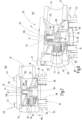
- Fig. 1 to 3 show a filter device 10 with a filter housing 12, which has at least two connection points 14, 16, such as an inlet 14 for unfiltered material and an outlet 16 for filtrate, and accommodates a replaceable filter element 18.
- the filter housing 12 is designed in three parts and has a main housing part 20, a lower housing part 22 and a cover part 24.
- the main housing part 20 is essentially cylindrical, with circumferential ribs 26 protruding from the cylinder wall, which are hexagonal on the circumference.
- the connection points for inlet 14 and outlet 16 are provided on opposite sides. These are also hexagonal on the outside.
- a housing bore 30 of the inlet 14 has a smaller diameter than a housing bore 32 of the outlet 16.
- the housing bores 30, 32 have an axial offset V to one another.
- the lower housing part 22 is screwed to the main housing part 20 from the underside via a thread 36 and sealed by a sealing ring (not shown in detail) in a circumferential groove.
- a cover part 24 is attached to the upper housing part 28 by means of four fastening screws 42.
- At least one valve device 44 is provided which, in an open position OS, enables a fluid flow between one of the connection points 14, 16 and the filter element 18 and in a closed position SS prevents this fluid flow.
- the valve device 44 can be moved between the open position OS and the closed position SS by means of a control device 46, which comprises the housing lower part 22 and the filter element 18.
- a control device 46 which comprises the housing lower part 22 and the filter element 18.
- an obliquely arranged separating disk 50 is inserted into the filter housing 12 from above through an opening 48 closed by the cover part 24, on which a valve device 44 in the form of an inflow valve 52 is provided.
- a ring 54 is provided on the separating disk 50 in a receiving socket 56, which cooperates with an outflow valve 58 provided on the cover part 24.
- the filter element 18 is screwed into the separating disk 50 with its threaded socket 60.
- one valve device 44 is the inflow valve 52, which is arranged in the fluid flow between the inlet 14 and an outer side 61 of the filter element 18 and has an inflow valve closing member 62 which comes into sealing contact with a valve seat 64 on the housing bore 30 of the inlet 14 and is urged into the closed position SS by a spring 66.
- the inflow valve closing member 62 can be moved between the open position OS and the closed position SS by rotating the filter element 18.
- a slotted guide 70 is provided on an adjacent upper end cap 68 of the filter element 18, which moves the inflow valve closing member 62 via a driver 72.
- the driver 72 is fastened to a fastening part 74 of the inflow valve closing member 62. Three of these fastening parts 74 are provided, which are arranged evenly offset on a pitch circle.
- the driver 72 is thus an integral component of the inflow valve closing member 62.
- the slotted guide 70 is a semicircular, partially annular axial projection 78 on the adjacent upper end cap 68 of the filter element 18, which has a larger radial distance A1 from a longitudinal axis LA of the filter element 18 at one end 82 than at another end 84.
- the axial Furthermore, projection 78 of the guide rail 70 is larger at one end 82 than at the other end 84, as can best be seen in Fig. 14 When viewed from the filter element 18, the height of the axial projection 78 increases in a counterclockwise direction.
- the separating disk 50 is arranged in a fixed position in the filter housing 12 and is supported on a shoulder 86 of the filter housing 12. On the outer circumference, the separating disk 50 is provided with a circumferential groove 88 in which a sealing ring 90 is arranged.
- the separating disk 50 has the receiving socket 56 parallel to the longitudinal axis LA of the filter device 10.
- the already mentioned inflow valve 52 is arranged on this receiving socket 56.
- a locking device 92 is provided which projects laterally.
- the spring 66 is arranged in the locking device 92, which preloads the inflow valve closing member 62 into the closed position SS.
- the locking device 92 also has three locking lugs 94 which are hooked onto the fastening parts 74 of the inflow valve closing member 62.
- a locking device 92 is provided on the cutting disk 50, which holds the inflow valve closing member 62 securely on the cutting disk 50 via at least one locking lug 94.
- the locking lugs 94 are arranged evenly offset on a pitch circle and guide the inflow valve closing member 62 on the outside 96 of the spring 66.
- valve device 44 in the form of the drain valve 58 is provided parallel to the longitudinal axis LA of the filter device 10, which is arranged in the fluid flow between the inner side 98 of the filter element 18 and the outlet 16 and has a closing valve closing member 100 with a T-shaped cross section, which comes into sealing contact with a stop 102 on the separating disk 50, which separates the inlet 14 and the outlet 16, and is urged into the closed position SS by a spring 104.
- the stop 102 is formed by the ring 54, which is L-shaped in cross section and is inserted into a circumferential groove 106 in the receiving nozzle 56.
- the ring 54 is preferably made of an elastomer.
- the Drain valve closing member 100 is T-shaped in cross section and held in a base 108, which is arranged either on the cover part 24 of the filter housing 12 or in a cage 110.
- the base 108 has a sleeve 112 in which a rod 114 of the drain valve closing member 100 is slidably arranged.
- the rod 114 is surrounded on the outside by the spring 104.
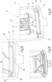
- a pin 118 is arranged, which is inserted into the Fig. 9 to 11 is visible.
- three pins 118 are provided on the threaded connector 60, which are evenly offset on a pitch circle. With these pins 118, it is possible to lift the drain valve closing element 100 from the stop 102 when screwing the filter element 18 into the separating disk 50.
- the cover part 24 essentially has the shape of a circular disk 120.
- arcuate fastening arms 122 are provided on the circular disk 120, into which the fastening screws 42 can engage.
- indentations 128 are provided on the outer circumference 126 of the cover part 24 in order to be able to lift the cover part 24 from the main housing part 20 past the heads 130 of the fastening screws 42.
- This solution has the advantage that the cover part 24 can be detached and lifted off the main housing part 20 without having to unscrew the fastening screws 42 from the main housing part 20.
- the cover part 24 On the underside 132, the cover part 24 has an axial extension 134 for centering and sealing against the main housing part 20.
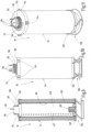
- the filter element 18 has a filter material 136 which is arranged between the upper end cap 68 and a lower end cap 138 and is enclosed by the latter.
- a support tube 140 with a perforation 142 is provided on an inner side 98 of the filter material 136.
- the upper end cap 68 has four projections 144 on the circumference which are arranged evenly offset on a pitch circle and which are intended to facilitate the handling of the filter element 18 when pulling it off the housing lower part 22.
- the lower end cap 138 of the filter element 18 is made of several parts, with a border ring 148 enclosing the filter material 136 and holding a bypass valve 150.
- the bypass valve 150 is interchangeably inserted into the border ring 148.
- This has a cage 152 with windows 154 in which a coarse-mesh filter fabric 156 is provided, as can be seen in the Fig. 15 can be seen.
- the bypass valve 150 has a bypass valve closing member 158 which is urged into the closed position SS by a spring 160.
- the bypass valve closing member 158 is T-shaped in cross section and comes to rest on a lower valve seat 162 on the rim ring 148.
- a fastening ring 166 is connected to this edging ring 148 via four S-shaped spring bands 164.
- the fastening ring 166 has a larger diameter than the edging ring 148.
- the fastening ring 166 can be inserted into the lower housing part 92 and fastened in a locking manner.
- the fastening ring 166 has a flange 168 and a nozzle 170 extending axially downwards from the flange 168, which is provided on the outside with a locking collar 172, via which the filter element 18 in the lower housing part 22 can be releasably secured in a recess 174, which has an inwardly drawn-in catch 178 at an upper end 176.
- drivers 180 are arranged on the flange 168 - also evenly offset on a pitch circle - which have inclined surfaces 182 and vertically extending contact surfaces 184 which can engage with rotating parts 186 on the housing base 22.
- the rotating parts 186 are in the Fig. 24 and 25 and also have a shape with an inclined surface 188 and a vertical surface 190, so that the drivers 180 and the rotating parts 186 can slide along one another in a clockwise direction of rotation of the housing lower part 22 when screwing it on and engage when rotating in the anti-clockwise direction of unscrewing.
- the lower housing part 22 is secured to the main housing part 20 via a thread 192.
- the filter element 18 has a second thread 194 so that it can be fastened in the separating disc 50.
- the thread pitches of these two threads 192, 194 differ to ensure that when the lower housing part 22 is unscrewed, the filter element 18 is first unscrewed from the separating disc 50 before it is unscrewed from the main housing part 20 together with the lower housing part 22.
- the spring elements 138 between the lower end cap parts 148, 160 are provided to enable length compensation. When screwing in, the procedure is reversed. First, the filter element 18 is screwed into the separating disc 50 and then the lower housing part 22 is finally screwed onto the main housing part 20.
- the filter element 18 in the filter housing 12 is also rotated.
- the inflow valve 52 and the outflow valve 58 are actuated by unscrewing the filter element 18, so that they go into the closed position SS due to the spring load.
- the spring elements 164 of the lower end cap 138 spring in and thus enable compensation.
- the filter element 18 is unscrewed from the recess 56 of the separating disc 50, the filter element 18 rotates on the separating disc 50 while the housing lower part 22 is further unscrewed.
- the housing lower part 22 and the main housing part 20 are disengaged.
- the filter element 18 remains fixed to the lower housing part 22 by a locking connection 172, 176 and is pulled out of the main housing part 20.
- the filter element 18 can be removed from the lower housing part 22 and replaced with a new filter element 18.
- the new filter element 18 When installing the new filter element 18, it is placed on the lower housing part 22 and pushed into the main housing part 20.
- the lower housing part 22 is screwed onto the main housing part 20.
- the filter element 18 is rotated and screwed into the separating disc 50.
- the inlet valve 52 and the outlet valve 58 are also moved to the respective open positions OS.
- the drivers 180 and rotating parts 186 on the lower end cap 138 and the lower housing part 22 can slide against each other over their respective inclined surfaces 182, 188, so that the lower housing part 22 can be completely screwed on without the filter element 18 rotating any further.
- the filter device 10 shows a solution to effectively separate an interior of a filter housing 12 from an inlet 14 and an outlet 16 by means of valve devices 44 when the filter housing 12 is unscrewed in order to replace the filter element 18. This has no equivalent in the prior art.
- top and bottom are meant in relation to the image plane of the respective drawing.
- the filter device can be arranged at an angle to the vertical.
Landscapes
- Chemical & Material Sciences (AREA)
- Chemical Kinetics & Catalysis (AREA)
- Filtration Of Liquid (AREA)
- Lubrication Details And Ventilation Of Internal Combustion Engines (AREA)
Claims (12)
- Elément de filtre pour un dispositif de filtrationcomprenant une enveloppe (12) de filtre, qui a au moins deux points (14, 16) de raccordement, comme une arrivée (14) de non filtrat et une évacuation (16) de filtrat, ainsi qui reçoit un élément (18) de filtre remplaçable,dans lequel il est prévu au moins un dispositif (44) de soupape, qui, dans une position (OS) d'ouverture, rend possible un flux de fluide entre l'un des points (14, 16) de raccordement et l'élément (18) de filtre et interdit ce flux de fluide dans une position (SS) de fermeture,dans lequel le dispositif (44) de soupape peut, au moyen d'un dispositif (46) de commande, passer entre la position (OS) d'ouverture et la position (SS) de fermeture,dans lequel l'élément (18) de filtre a un matériau (136) filtrant, qui est disposé entre la coiffe (68) d'extrémité supérieure et une coiffe (138) d'extrémité inférieure et est enchâssé par celles-ci, etdans lequel il est prévu sur la face (98) intérieure du matériau (136) filtrant un tube (140) d'appui ayant une série (142) de trous,caractériséen ce qu'il est prévu sur la coiffe (68) d'extrémité supérieure un guidage (70) à coulisse et au moins une broche (118), eten ce que la broche (118) respective est montée sur une face intérieure d'une tubulure (60) filetée de l'élément (18) de filtre.
- Elément de filtre suivant la revendication 1, caractérisé en ce que le guidage (70) à coulisse est une saillie (78) axiale, annulaire par tronçons et formant un demi-cercle sur la coiffe (68) d'extrémité supérieure de l'élément (18) de filtre, qui possède à l'une de ses extrémités (82) une distance (A1) radiale plus grande d'un axe (LA) longitudinal de l'élément (18) de filtre qu'à une autre extrémité (84).
- Elément de filtre suivant la revendication 2, caractérisé en ce que la saillie (78) axiale du guidage (70) à coulisse est à la une extrémité (82) plus grande qu'à l'autre extrémité (84), de manière à ce que la hauteur de la saillie (78) axiale augmente dans un sens contraire au sens des aiguilles d'une montre.
- Elément de filtre suivant l'une des revendications précédentes, caractérisé en ce qu'il est prévu sur la tubulure (60) filetée trois ou plusieurs broches (118), qui sont disposées de manière décalée uniformément sur un cercle partiel.
- Elément de filtre suivant l'une des revendications précédentes, caractérisé en ce que la coiffe (68) d'extrémité supérieure a, du côté du pourtour, quatre ressauts (144) disposés de manière décalée uniformément sur un cercle partiel.
- Elément de filtre suivant l'une des revendications précédentes, caractérisé en ce que la coiffe (138) d'extrémité inférieure de l'élément (18) de filtre est réalisée en plusieurs parties, en ce qu'un anneau (148) de bordure enchâsse le matériau (136) filtrant et maintient une soupape (150) de dérivation, et en ce que la soupape (150) de dérivation est insérée, de manière à pouvoir être remplacée, dans l'anneau (148) de bordure.
- Elément de filtre suivant la revendication 6, caractérisé en ce que la soupape (150) de dérivation a une cage (152) à fenêtres (154), dans lesquelles un tissu (156) filtrant à grosse maille est prévu.
- Elément de filtre suivant la revendication 6 ou 7, caractérisé en ce que la soupape (150) de dérivation a un obturateur (158) de soupape de dérivation, qui est mis dans la position (SS) de fermeture par un ressort (160), et en ce que l'obturateur (158) de la soupape de dérivation est en forme de 1 en section transversale et vient en contact avec un siège (162) inférieur de soupape sur l'anneau (148) de bordure.
- Elément de filtre suivant l'une des revendications 6 à 8, caractérisé en ce que, avec l'anneau (148) de bordure est assemblé, par quatre bandes (164) de ressort en forme de S, un anneau (166) de fixation, qui a un diamètre plus grand que l'anneau (148) de bordure.
- Elément de filtre suivant la revendication 9, caractérisé en ce que l'anneau (166) de fixation a une bride (168) et, s'étendant en s'éloignant vers le bas axialement de la bride (168), une tubulure (170), qui est pourvue du côté extérieur d'un collet (172) d'encliquetage.
- Elément de filtre suivant la revendication 10, caractérisé en ce que sur la bride (168) sont disposés décalés uniformément sur un cercle partiel, quatre entraîneurs (180), qui ont des surfaces (182) inclinées et des surfaces (184) d'application s'étendant verticalement.
- Elément de filtre suivant l'une des revendications précédentes, caractérisé en ce qu'il a un deuxième filetage (194).
Applications Claiming Priority (2)
| Application Number | Priority Date | Filing Date | Title |
|---|---|---|---|
| DE102021002511.3A DE102021002511A1 (de) | 2021-05-12 | 2021-05-12 | Filtervorrichtung |
| EP22170189.9A EP4088801B1 (fr) | 2021-05-12 | 2022-04-27 | Dispositif filtre |
Related Parent Applications (3)
| Application Number | Title | Priority Date | Filing Date |
|---|---|---|---|
| EP22170189.9A Division EP4088801B1 (fr) | 2021-05-12 | 2022-04-27 | Dispositif filtre |
| EP22170189.9A Previously-Filed-Application EP4088801B1 (fr) | 2021-05-12 | 2022-04-27 | Dispositif filtre |
| EP22170189.9A Division-Into EP4088801B1 (fr) | 2021-05-12 | 2022-04-27 | Dispositif filtre |
Publications (4)
| Publication Number | Publication Date |
|---|---|
| EP4357000A2 EP4357000A2 (fr) | 2024-04-24 |
| EP4357000A3 EP4357000A3 (fr) | 2024-05-01 |
| EP4357000B1 true EP4357000B1 (fr) | 2024-12-18 |
| EP4357000C0 EP4357000C0 (fr) | 2024-12-18 |
Family
ID=81388972
Family Applications (2)
| Application Number | Title | Priority Date | Filing Date |
|---|---|---|---|
| EP22170189.9A Active EP4088801B1 (fr) | 2021-05-12 | 2022-04-27 | Dispositif filtre |
| EP24151211.0A Active EP4357000B1 (fr) | 2021-05-12 | 2022-04-27 | Dispositif filtre |
Family Applications Before (1)
| Application Number | Title | Priority Date | Filing Date |
|---|---|---|---|
| EP22170189.9A Active EP4088801B1 (fr) | 2021-05-12 | 2022-04-27 | Dispositif filtre |
Country Status (2)
| Country | Link |
|---|---|
| EP (2) | EP4088801B1 (fr) |
| DE (1) | DE102021002511A1 (fr) |
Families Citing this family (2)
| Publication number | Priority date | Publication date | Assignee | Title |
|---|---|---|---|---|
| DE102022004844A1 (de) | 2022-12-21 | 2024-06-27 | Hydac Fluidcarecenter Gmbh | Filtervorrichtung |
| DE102023003101A1 (de) | 2023-07-18 | 2025-01-23 | Hydac Filtertechnik Gmbh | Filtervorrichtung und Filterelement |
Family Cites Families (5)
| Publication number | Priority date | Publication date | Assignee | Title |
|---|---|---|---|---|
| DE202007008483U1 (de) | 2006-08-25 | 2008-01-03 | Mann+Hummel Gmbh | Funktionselement zum Betätigen eines Ventils |
| DE102008036055B4 (de) | 2008-08-01 | 2010-04-08 | Hydac Filtertechnik Gmbh | Filtervorrichtung und Filterelement |
| DE102017009255A1 (de) * | 2017-10-05 | 2019-04-11 | Mann+Hummel Gmbh | Filterelement mit Entlüftungsfunktion für den hängenden Anschluss an einem Filterkopf sowie Filtersystem |
| DE202019102432U1 (de) | 2019-04-30 | 2019-05-10 | Nordson Corporation | Filtervorrichtung zum Filtern von Fluiden |
| DE102020004489A1 (de) | 2020-07-24 | 2022-01-27 | H Y D A C Filtertechnik GmbH | Filtervorrichtung |
-
2021
- 2021-05-12 DE DE102021002511.3A patent/DE102021002511A1/de active Pending
-
2022
- 2022-04-27 EP EP22170189.9A patent/EP4088801B1/fr active Active
- 2022-04-27 EP EP24151211.0A patent/EP4357000B1/fr active Active
Also Published As
| Publication number | Publication date |
|---|---|
| DE102021002511A1 (de) | 2022-11-17 |
| EP4088801C0 (fr) | 2024-02-21 |
| EP4088801A1 (fr) | 2022-11-16 |
| EP4357000A3 (fr) | 2024-05-01 |
| EP4357000C0 (fr) | 2024-12-18 |
| EP4357000A2 (fr) | 2024-04-24 |
| EP4088801B1 (fr) | 2024-02-21 |
Similar Documents
| Publication | Publication Date | Title |
|---|---|---|
| EP0748646B1 (fr) | Filtre de liquide | |
| EP0692292B1 (fr) | Filtre à liquides | |
| DE3018158C2 (de) | Preßluftarmatur | |
| EP3185982B1 (fr) | Dispositif de purification d'un liquide ou un gas et dispositif de separation | |
| EP2054133B1 (fr) | Filtre à liquide, en particulier pour véhicules automobiles | |
| EP3268106B1 (fr) | Filtre comprenant une soupape de contournement de filtre et cartouche filtrante associée | |
| DE68911842T2 (de) | Filtersystem. | |
| EP3213803B1 (fr) | Système de filtre | |
| DE19605425A1 (de) | Flüssigkeitsfilter mit Filterumgehungsventil und filterelementseitiger Dichtfläche | |
| WO2016198136A1 (fr) | Dispositif filtre | |
| EP3972713B1 (fr) | Dispositif de filtration | |
| DE102013019807B4 (de) | Filtervorrichtung und Filterelement | |
| DE29610290U1 (de) | Flüssigkeitsfilter | |
| EP4088801B1 (fr) | Dispositif filtre | |
| DE2528932C2 (de) | Filteranordnung | |
| DE102019108955A1 (de) | Filter mit einem Filtergehäuse aus zwei Filtergehäuseteilen und mit einem im Filtergehäuse auswechselbar angeordneten Filtereinsatz sowie Filtereinsatz für den Filter | |
| EP4146366B1 (fr) | Appareil de filtration | |
| DE112014000535B4 (de) | Rückspülbarer Flüssigkeitsfilter | |
| DE602004012297T2 (de) | Rückspülbarer filter mit schleuderabreinigung | |
| DE10141992C1 (de) | Filtervorrichtung, insbesondere für Hochdruckanwendungen bei einer Polymerschmelze-Filtration | |
| EP4171781B1 (fr) | Dispositif de filtration comportant un élément filtrant | |
| DE102014010007B4 (de) | Filtervorrichtung und Filterelemente | |
| DE102019108957A1 (de) | Filter mit einem Filtergehäuse, mit einem auswechselbaren Filtereinsatz und mit einem Dichtungsträger daran | |
| DE1761598B1 (de) | Filtriervorrichtung | |
| EP3609595B1 (fr) | Dispositif servant à remplacer un élément filtrant |
Legal Events
| Date | Code | Title | Description |
|---|---|---|---|
| PUAI | Public reference made under article 153(3) epc to a published international application that has entered the european phase |
Free format text: ORIGINAL CODE: 0009012 |
|
| STAA | Information on the status of an ep patent application or granted ep patent |
Free format text: STATUS: REQUEST FOR EXAMINATION WAS MADE |
|
| REG | Reference to a national code |
Ipc: B01D0029150000 Ref country code: DE Ref legal event code: R079 Ref document number: 502022002458 Country of ref document: DE Free format text: PREVIOUS MAIN CLASS: B01D0035153000 |
|
| PUAL | Search report despatched |
Free format text: ORIGINAL CODE: 0009013 |
|
| STAA | Information on the status of an ep patent application or granted ep patent |
Free format text: STATUS: EXAMINATION IS IN PROGRESS |
|
| 17P | Request for examination filed |
Effective date: 20240110 |
|
| AC | Divisional application: reference to earlier application |
Ref document number: 4088801 Country of ref document: EP Kind code of ref document: P |
|
| AK | Designated contracting states |
Kind code of ref document: A2 Designated state(s): AL AT BE BG CH CY CZ DE DK EE ES FI FR GB GR HR HU IE IS IT LI LT LU LV MC MK MT NL NO PL PT RO RS SE SI SK SM TR |
|
| AK | Designated contracting states |
Kind code of ref document: A3 Designated state(s): AL AT BE BG CH CY CZ DE DK EE ES FI FR GB GR HR HU IE IS IT LI LT LU LV MC MK MT NL NO PL PT RO RS SE SI SK SM TR |
|
| RIC1 | Information provided on ipc code assigned before grant |
Ipc: B01D 35/153 20060101ALI20240328BHEP Ipc: B01D 35/147 20060101ALI20240328BHEP Ipc: B01D 29/15 20060101AFI20240328BHEP |
|
| 17Q | First examination report despatched |
Effective date: 20240417 |
|
| GRAP | Despatch of communication of intention to grant a patent |
Free format text: ORIGINAL CODE: EPIDOSNIGR1 |
|
| STAA | Information on the status of an ep patent application or granted ep patent |
Free format text: STATUS: GRANT OF PATENT IS INTENDED |
|
| INTG | Intention to grant announced |
Effective date: 20240924 |
|
| GRAS | Grant fee paid |
Free format text: ORIGINAL CODE: EPIDOSNIGR3 |
|
| GRAA | (expected) grant |
Free format text: ORIGINAL CODE: 0009210 |
|
| STAA | Information on the status of an ep patent application or granted ep patent |
Free format text: STATUS: THE PATENT HAS BEEN GRANTED |
|
| RBV | Designated contracting states (corrected) |
Designated state(s): AL AT BE BG CH CY CZ DE DK EE ES FI FR GB GR HR HU IE IS IT LI LT LU LV MC MK MT NL NO PL PT RO RS SE SI SK SM TR |
|
| AC | Divisional application: reference to earlier application |
Ref document number: 4088801 Country of ref document: EP Kind code of ref document: P |
|
| AK | Designated contracting states |
Kind code of ref document: B1 Designated state(s): AL AT BE BG CH CY CZ DE DK EE ES FI FR GB GR HR HU IE IS IT LI LT LU LV MC MK MT NL NO PL PT RO RS SE SI SK SM TR |
|
| REG | Reference to a national code |
Ref country code: CH Ref legal event code: EP |
|
| REG | Reference to a national code |
Ref country code: DE Ref legal event code: R096 Ref document number: 502022002458 Country of ref document: DE |
|
| REG | Reference to a national code |
Ref country code: IE Ref legal event code: FG4D Free format text: LANGUAGE OF EP DOCUMENT: GERMAN |
|
| U01 | Request for unitary effect filed |
Effective date: 20241218 |
|
| U07 | Unitary effect registered |
Designated state(s): AT BE BG DE DK EE FI FR IT LT LU LV MT NL PT RO SE SI Effective date: 20250102 |
|
| PG25 | Lapsed in a contracting state [announced via postgrant information from national office to epo] |
Ref country code: HR Free format text: LAPSE BECAUSE OF FAILURE TO SUBMIT A TRANSLATION OF THE DESCRIPTION OR TO PAY THE FEE WITHIN THE PRESCRIBED TIME-LIMIT Effective date: 20241218 |
|
| PG25 | Lapsed in a contracting state [announced via postgrant information from national office to epo] |
Ref country code: NO Free format text: LAPSE BECAUSE OF FAILURE TO SUBMIT A TRANSLATION OF THE DESCRIPTION OR TO PAY THE FEE WITHIN THE PRESCRIBED TIME-LIMIT Effective date: 20250318 |
|
| PG25 | Lapsed in a contracting state [announced via postgrant information from national office to epo] |
Ref country code: GR Free format text: LAPSE BECAUSE OF FAILURE TO SUBMIT A TRANSLATION OF THE DESCRIPTION OR TO PAY THE FEE WITHIN THE PRESCRIBED TIME-LIMIT Effective date: 20250319 |
|
| PG25 | Lapsed in a contracting state [announced via postgrant information from national office to epo] |
Ref country code: RS Free format text: LAPSE BECAUSE OF FAILURE TO SUBMIT A TRANSLATION OF THE DESCRIPTION OR TO PAY THE FEE WITHIN THE PRESCRIBED TIME-LIMIT Effective date: 20250318 |
|
| U20 | Renewal fee for the european patent with unitary effect paid |
Year of fee payment: 4 Effective date: 20250430 |
|
| PG25 | Lapsed in a contracting state [announced via postgrant information from national office to epo] |
Ref country code: SM Free format text: LAPSE BECAUSE OF FAILURE TO SUBMIT A TRANSLATION OF THE DESCRIPTION OR TO PAY THE FEE WITHIN THE PRESCRIBED TIME-LIMIT Effective date: 20241218 |
|
| PG25 | Lapsed in a contracting state [announced via postgrant information from national office to epo] |
Ref country code: PL Free format text: LAPSE BECAUSE OF FAILURE TO SUBMIT A TRANSLATION OF THE DESCRIPTION OR TO PAY THE FEE WITHIN THE PRESCRIBED TIME-LIMIT Effective date: 20241218 |
|
| PG25 | Lapsed in a contracting state [announced via postgrant information from national office to epo] |
Ref country code: ES Free format text: LAPSE BECAUSE OF FAILURE TO SUBMIT A TRANSLATION OF THE DESCRIPTION OR TO PAY THE FEE WITHIN THE PRESCRIBED TIME-LIMIT Effective date: 20241218 |
|
| PG25 | Lapsed in a contracting state [announced via postgrant information from national office to epo] |
Ref country code: IS Free format text: LAPSE BECAUSE OF FAILURE TO SUBMIT A TRANSLATION OF THE DESCRIPTION OR TO PAY THE FEE WITHIN THE PRESCRIBED TIME-LIMIT Effective date: 20250418 |
|
| PGFP | Annual fee paid to national office [announced via postgrant information from national office to epo] |
Ref country code: CH Payment date: 20250501 Year of fee payment: 4 |
|
| PG25 | Lapsed in a contracting state [announced via postgrant information from national office to epo] |
Ref country code: SK Free format text: LAPSE BECAUSE OF FAILURE TO SUBMIT A TRANSLATION OF THE DESCRIPTION OR TO PAY THE FEE WITHIN THE PRESCRIBED TIME-LIMIT Effective date: 20241218 |
|
| PG25 | Lapsed in a contracting state [announced via postgrant information from national office to epo] |
Ref country code: CZ Free format text: LAPSE BECAUSE OF FAILURE TO SUBMIT A TRANSLATION OF THE DESCRIPTION OR TO PAY THE FEE WITHIN THE PRESCRIBED TIME-LIMIT Effective date: 20241218 |
|
| PLBE | No opposition filed within time limit |
Free format text: ORIGINAL CODE: 0009261 |
|
| STAA | Information on the status of an ep patent application or granted ep patent |
Free format text: STATUS: NO OPPOSITION FILED WITHIN TIME LIMIT |
|
| REG | Reference to a national code |
Ref country code: CH Ref legal event code: L10 Free format text: ST27 STATUS EVENT CODE: U-0-0-L10-L00 (AS PROVIDED BY THE NATIONAL OFFICE) Effective date: 20251029 |
|
| 26N | No opposition filed |
Effective date: 20250919 |
|
| PG25 | Lapsed in a contracting state [announced via postgrant information from national office to epo] |
Ref country code: MC Free format text: LAPSE BECAUSE OF FAILURE TO SUBMIT A TRANSLATION OF THE DESCRIPTION OR TO PAY THE FEE WITHIN THE PRESCRIBED TIME-LIMIT Effective date: 20241218 |
|
| PGFP | Annual fee paid to national office [announced via postgrant information from national office to epo] |
Ref country code: GB Payment date: 20260210 Year of fee payment: 5 |
|
| PG25 | Lapsed in a contracting state [announced via postgrant information from national office to epo] |
Ref country code: IE Free format text: LAPSE BECAUSE OF NON-PAYMENT OF DUE FEES Effective date: 20250427 |
|
| REG | Reference to a national code |
Ref country code: CH Ref legal event code: U11 Free format text: ST27 STATUS EVENT CODE: U-0-0-U10-U11 (AS PROVIDED BY THE NATIONAL OFFICE) Effective date: 20260501 |