EP0079003B1 - Four à longerons mobiles - Google Patents
Four à longerons mobiles Download PDFInfo
- Publication number
- EP0079003B1 EP0079003B1 EP82109981A EP82109981A EP0079003B1 EP 0079003 B1 EP0079003 B1 EP 0079003B1 EP 82109981 A EP82109981 A EP 82109981A EP 82109981 A EP82109981 A EP 82109981A EP 0079003 B1 EP0079003 B1 EP 0079003B1
- Authority
- EP
- European Patent Office
- Prior art keywords
- wheel
- walking beam
- beam furnace
- stroke
- walking
- Prior art date
- Legal status (The legal status is an assumption and is not a legal conclusion. Google has not performed a legal analysis and makes no representation as to the accuracy of the status listed.)
- Expired
Links
- 230000005540 biological transmission Effects 0.000 claims description 17
- NJPPVKZQTLUDBO-UHFFFAOYSA-N novaluron Chemical compound C1=C(Cl)C(OC(F)(F)C(OC(F)(F)F)F)=CC=C1NC(=O)NC(=O)C1=C(F)C=CC=C1F NJPPVKZQTLUDBO-UHFFFAOYSA-N 0.000 claims 2
- 238000012423 maintenance Methods 0.000 abstract 2
- 230000002093 peripheral effect Effects 0.000 abstract 1
- 230000033001 locomotion Effects 0.000 description 14
- 238000000137 annealing Methods 0.000 description 3
- 238000006073 displacement reaction Methods 0.000 description 2
- 230000000903 blocking effect Effects 0.000 description 1
- 230000008878 coupling Effects 0.000 description 1
- 238000010168 coupling process Methods 0.000 description 1
- 238000005859 coupling reaction Methods 0.000 description 1
- 238000000034 method Methods 0.000 description 1
- 230000000284 resting effect Effects 0.000 description 1
Images


Classifications
-
- B—PERFORMING OPERATIONS; TRANSPORTING
- B65—CONVEYING; PACKING; STORING; HANDLING THIN OR FILAMENTARY MATERIAL
- B65G—TRANSPORT OR STORAGE DEVICES, e.g. CONVEYORS FOR LOADING OR TIPPING, SHOP CONVEYOR SYSTEMS OR PNEUMATIC TUBE CONVEYORS
- B65G25/00—Conveyors comprising a cyclically-moving, e.g. reciprocating, carrier or impeller which is disengaged from the load during the return part of its movement
- B65G25/02—Conveyors comprising a cyclically-moving, e.g. reciprocating, carrier or impeller which is disengaged from the load during the return part of its movement the carrier or impeller having different forward and return paths of movement, e.g. walking beam conveyors
-
- F—MECHANICAL ENGINEERING; LIGHTING; HEATING; WEAPONS; BLASTING
- F26—DRYING
- F26B—DRYING SOLID MATERIALS OR OBJECTS BY REMOVING LIQUID THEREFROM
- F26B15/00—Machines or apparatus for drying objects with progressive movement; Machines or apparatus with progressive movement for drying batches of material in compact form
- F26B15/10—Machines or apparatus for drying objects with progressive movement; Machines or apparatus with progressive movement for drying batches of material in compact form with movement in a path composed of one or more straight lines, e.g. compound, the movement being in alternate horizontal and vertical directions
- F26B15/12—Machines or apparatus for drying objects with progressive movement; Machines or apparatus with progressive movement for drying batches of material in compact form with movement in a path composed of one or more straight lines, e.g. compound, the movement being in alternate horizontal and vertical directions the lines being all horizontal or slightly inclined
-
- F—MECHANICAL ENGINEERING; LIGHTING; HEATING; WEAPONS; BLASTING
- F27—FURNACES; KILNS; OVENS; RETORTS
- F27B—FURNACES, KILNS, OVENS OR RETORTS IN GENERAL; OPEN SINTERING OR LIKE APPARATUS
- F27B9/00—Furnaces through which the charge is moved mechanically, e.g. of tunnel type; Similar furnaces in which the charge moves by gravity
- F27B9/14—Furnaces through which the charge is moved mechanically, e.g. of tunnel type; Similar furnaces in which the charge moves by gravity characterised by the path of the charge during treatment; characterised by the means by which the charge is moved during treatment
- F27B9/20—Furnaces through which the charge is moved mechanically, e.g. of tunnel type; Similar furnaces in which the charge moves by gravity characterised by the path of the charge during treatment; characterised by the means by which the charge is moved during treatment the charge moving in a substantially straight path
- F27B9/201—Furnaces through which the charge is moved mechanically, e.g. of tunnel type; Similar furnaces in which the charge moves by gravity characterised by the path of the charge during treatment; characterised by the means by which the charge is moved during treatment the charge moving in a substantially straight path walking beam furnace
- F27B9/202—Conveyor mechanisms therefor
- F27B9/203—Conveyor mechanisms therefor having ramps
Definitions
- the invention relates to a walking beam furnace with an alternating arranged fixed and walking beam hearth, in which the lifting beams are assigned to rollers which are movable in relation to the working stroke and are mounted in a lifting frame.
- Such a walking beam furnace is known from DE-A-2 926 661.
- Each walking beam can be lifted with the annealing material and then moved by means of lifting rollers which can be moved on the inclines, and then moved, whereupon the walking beams are lowered again under the furnace sole and returned to the original position.
- the annealing material can be moved step by step through the annealing furnace.
- the slopes on which the lifting rollers run are extended so far that the lifting beams can be lowered to a lower position in which they and the fixed beams are accessible for repair purposes.
- the extension drive rod which is articulated on a lifting frame, serves as the drive for the movement of the lifting rollers and is attached to a swivel lever which is mounted on the one hand in a bracket and on the other hand is acted upon by a piston-cylinder unit.
- the lifting frame is moved in accordance with the piston stroke of the piston-cylinder unit and secured against further displacement.
- the attachment rods are then released from the swivel lever and the piston of the piston-cylinder unit is moved back into the other extreme position.
- an extension is inserted between the attachment rod and the swivel lever and the locking of the lifting frame is released.
- the piston-cylinder unit can then be extended again so that there is an additional downward movement of the walking beam.
- the front bar is extended step by step and the lifting rollers roll down the slope more and more.
- the walking beam follows this lowering movement accordingly.
- the walking beam furnace is increased in size, then the weight differences become noticeable and either lead to the need to divide the repair stroke into a large number of individual steps or to significantly increase the drive device for the walking beam.
- the invention has for its object to improve the walking beam furnace of the type mentioned in such a way that with a simple structure and with as possible Little effort the working stroke requires a relatively lower driving force and the repair stroke is carried out at a higher speed.
- the solution to this problem according to the invention consists in a power transmission element which is articulated on the one hand on a lifting frame and on the other hand on a rotatably mounted wheel and in a bearing block for the wheel which has a plurality of bolt bushings for locking bolts which cooperate with a plurality of bores distributed over the circumference of the wheel.
- the holes distributed in the wheel also serve to connect a pivoting eye on the drive unit by means of an interchangeable bolt at different points with the wheel, so that, despite a relatively small stroke of the drive unit, there is gradually half a turn of the wheel or more.
- the slopes can also be provided with a flat slope for the working stroke and a steeper slope for the repair or lowering stroke.
- This configuration of the bevels has the advantage that the working stroke only needs to be small and thus the effort required over a flat bevel is considerably less even under high loads than with a steeper bevel, as is provided for the lowering stroke.
- a variable translation of the walking beam drive can be achieved according to the invention by a power transmission element articulated on the wheel without support on the wheel circumference.
- this power transmission element consists of an attachment rod connected to the lifting frame, this is articulated on the wheel in such a way that for the working stroke, the rotation of the wheel around the stroke of the drive unit causes only a slight displacement movement of the attachment rod and thus a small lifting movement of the lifting beam, while the lowering stroke for Repair purposes corresponds to an almost tangential movement of the attachment rod on the wheel with a correspondingly large stroke.
- a flexible element for example a rope or a link chain
- it is articulated on the wheel in a corresponding manner, but for the working stroke it rests on a small diameter support arranged coaxially to the wheel.
- the radius of the support determines the movement of the lifting frame and the working stroke takes place. If the wheel is gradually rotated by means of the drive unit so that the force transmission element lifts off the support, the movement of the lifting frame increases in accordance with the distance of the elongated, flexible force transmission element from the wheel pivot point, and the lowering stroke is initiated.
- the wheel is designed so that the force transmission element can rest on the wheel circumference. In this case, a subdivision into working stroke and lowering stroke can only be achieved with the help of different inclination angles of the slope.
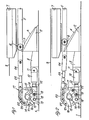
- a foundation 1 is shown schematically, on which inclined trestles 2 are fastened, which in the embodiment according to FIGS. 1 to 4 are provided with rails with a flatter slope 3 and a steeper slope 4.
- a lifting frame 5 there are rollers 6, which can be moved on the slopes 3 and 4 and under a lifting beam 7.
- the walking beam 7 protrudes a little beyond a furnace sole 8 of the walking beam furnace when the walking beam drive, as shown in FIG. 1, has moved into the upper position of the working stroke.
- a bracket 9 is attached to the foundation 1, on which a piston-cylinder unit 10 is supported via a pivot point 11.
- the piston-cylinder unit 10 has a push rod 12 which is inserted into a bearing block 13.
- a bearing 14 for a shaft 15 with a wheel 16 is fastened on the bearing block 13.
- On the circumference of the wheel 16 there are bores 17 which can be made to coincide with corresponding bolt bushings 18 in the bearing block 13.
- the push rod 12 can be brought into drive connection with this wheel 16 by means of a connecting bolt 19 inserted through one of the bores 17 in the wheel 16.
- a link chain 20 is connected on the one hand by means of a connecting bolt 21 on the circumference of the wheel 16 and on the other hand via an adjusting spindle 23 and a coupling fork 24 to the lifting frame 5.
- Tab supports 22 are arranged on the circumference of the wheel 16, so that the link chain 20 resting on the wheel 16 always takes the same distance from the center of rotation of the wheel 16.
- the wheel 16 rotates into the position shown in FIG. 2, the rollers 6 on the lifting frame 5 move along the flat gradient 3 of the slope, and the lifting beam 7 enters the in Fig. 2 shown lower position of the working stroke.
- the push rod 12 of the piston-cylinder unit 10 is retracted and the walking beam 7 again assumes the position shown in FIG. 1.
- a locking bolt 25 is first inserted into a bolt bushing 18 of the bearing block 13 and a bore 17 of the wheel 16, the connecting bolt 19 between the push rod 12 and the wheel 16 6 pulled out, the push rod 12 retracted into the piston-cylinder unit 10 and the connecting bolt 19 again in the bore 17 and inserted through the push rod 12. Now the locking pin 25 is removed again and the push rod can be extended again. This process is repeated, as in 3 and 4 shown until the lower position of the lowering stroke is reached for repair purposes.
- the translation of motion between the piston-cylinder unit 10 and the lifting frame 5 is essentially constant, so that the variable translation is achieved exclusively by the flatter gradient 3 and the steeper gradient 4 of the inclined blocks 2.
- the trestles 2 are equipped with a rail 26 of constant incline, but the link chain 27 and the wheel 28 are redesigned such that the force transmission element cannot rest on the circumference of the wheel 28, but as in FIG. 5 shown, rests laterally on a support of smaller diameter.
- the stroke can be achieved for the stroke of the push rod 12 of the piston-cylinder unit 10 as shown in FIGS. 5 and 6, while a further rotation of the wheel 28 as shown in FIGS. 3 and 4 leads to a considerably larger stroke, since the Connecting bolt 21 for the link chain 27 then moved substantially tangentially to the circumference of the wheel 28.
- the lifting frame can be locked in the gradual lowering movement by the same means and in the same place that are used for the gradual release and fastening of the push rod 12 of the piston-cylinder unit 10 on the wheel 16, 28.
- Another advantage of the device according to the invention is that the drive connection between the wheel 16, 28 and the lifting frame 5 does not have to be released. and that no extensions are required.
Landscapes
- Engineering & Computer Science (AREA)
- Mechanical Engineering (AREA)
- General Engineering & Computer Science (AREA)
- Heat Treatments In General, Especially Conveying And Cooling (AREA)
- Tunnel Furnaces (AREA)
- Reciprocating Conveyors (AREA)
Claims (7)
Priority Applications (1)
| Application Number | Priority Date | Filing Date | Title |
|---|---|---|---|
| AT82109981T ATE19149T1 (de) | 1981-11-07 | 1982-10-28 | Hubbalkenofen. |
Applications Claiming Priority (2)
| Application Number | Priority Date | Filing Date | Title |
|---|---|---|---|
| DE3144328A DE3144328C2 (de) | 1981-11-07 | 1981-11-07 | Hubbalkenofen |
| DE3144328 | 1981-11-07 |
Publications (3)
| Publication Number | Publication Date |
|---|---|
| EP0079003A2 EP0079003A2 (fr) | 1983-05-18 |
| EP0079003A3 EP0079003A3 (en) | 1983-07-20 |
| EP0079003B1 true EP0079003B1 (fr) | 1986-04-09 |
Family
ID=6145900
Family Applications (1)
| Application Number | Title | Priority Date | Filing Date |
|---|---|---|---|
| EP82109981A Expired EP0079003B1 (fr) | 1981-11-07 | 1982-10-28 | Four à longerons mobiles |
Country Status (4)
| Country | Link |
|---|---|
| US (1) | US4466792A (fr) |
| EP (1) | EP0079003B1 (fr) |
| AT (1) | ATE19149T1 (fr) |
| DE (1) | DE3144328C2 (fr) |
Families Citing this family (7)
| Publication number | Priority date | Publication date | Assignee | Title |
|---|---|---|---|---|
| GB2207114B (en) * | 1985-04-13 | 1989-11-22 | Tidd Strongbox Ltd | Article handling system |
| US4928811A (en) * | 1988-12-07 | 1990-05-29 | Glenn Waineo | Walking beam apparatus |
| NL9300055A (nl) * | 1993-01-12 | 1994-08-01 | Elten Systems Bv | Stappentransporteur. |
| US5605427A (en) * | 1993-07-06 | 1997-02-25 | Hammond; Theodore A. | Level gravity conveyor with gravity return of transfer units |
| DE19860800A1 (de) * | 1998-12-30 | 2000-07-06 | Berchtold Gmbh & Co Geb | Medizinische Leuchte |
| US6364093B1 (en) | 2000-02-25 | 2002-04-02 | Boltech, Inc. | Walking beam conveyor and method |
| CN110340658B (zh) * | 2019-07-10 | 2021-10-26 | 浙江引春机械有限公司 | 流水线组装装置 |
Family Cites Families (8)
| Publication number | Priority date | Publication date | Assignee | Title |
|---|---|---|---|---|
| US2684769A (en) * | 1949-08-24 | 1954-07-27 | Sunbeam Corp | Step-by-step feeding mechanism |
| DE1533980A1 (de) * | 1967-03-18 | 1970-02-12 | Koppers Wistra Ofenbau Gmbh | Hubbalkenofen |
| JPS5029687B1 (fr) * | 1971-04-23 | 1975-09-25 | ||
| DE2142462A1 (de) * | 1971-08-25 | 1973-07-12 | Norbert Dr Steuler | Foerdervorrichtung mit schreitbalken zum transport von formkoerpern durch eine behandlungszone, insbesondere einen brennofen |
| GB1417373A (en) * | 1974-02-25 | 1975-12-10 | Prepovske Strojirny Narodni Po | Conveyer |
| GB1473645A (en) * | 1974-06-27 | 1977-05-18 | British Steel Corp | Walking beam furnaces |
| US4116619A (en) * | 1977-05-26 | 1978-09-26 | Btu Engineering Corporation | Multiple beam furnace |
| DE2926661A1 (de) * | 1979-07-02 | 1981-01-15 | Italimpianti Deutschland Indus | Hubbalkenofen |
-
1981
- 1981-11-07 DE DE3144328A patent/DE3144328C2/de not_active Expired
-
1982
- 1982-10-28 EP EP82109981A patent/EP0079003B1/fr not_active Expired
- 1982-10-28 AT AT82109981T patent/ATE19149T1/de not_active IP Right Cessation
- 1982-11-05 US US06/440,252 patent/US4466792A/en not_active Expired - Fee Related
Also Published As
| Publication number | Publication date |
|---|---|
| DE3144328A1 (de) | 1983-05-19 |
| DE3144328C2 (de) | 1986-07-17 |
| EP0079003A3 (en) | 1983-07-20 |
| ATE19149T1 (de) | 1986-04-15 |
| EP0079003A2 (fr) | 1983-05-18 |
| US4466792A (en) | 1984-08-21 |
Similar Documents
| Publication | Publication Date | Title |
|---|---|---|
| DE2858194C2 (fr) | ||
| DE69202328T2 (de) | Aufwickelvorrichtung zum Auf- und Abwickeln eines Kabels auf eine Trommel. | |
| DE4106371C2 (fr) | ||
| DE69000289T2 (de) | Kran mit anhebbarem ausleger und mit einer ausleger-rueckstossvorrichtung. | |
| DE3640183C2 (fr) | ||
| DE2208777A1 (de) | Scherenhebetisch | |
| DE2137001C3 (de) | Hebevorrichtung mit Schwenkarm | |
| EP0079003B1 (fr) | Four à longerons mobiles | |
| EP3448796B1 (fr) | Grue comprenant un dispositif de déplacement de contrepoids et procédé de déplacement d'un contrepoids sur une grue | |
| DE2916042B2 (de) | Drehturm für zwei unabhängig voneinander heb- und senkbare Gießpfannen | |
| DE1801343A1 (de) | Laufkran fuer Giesstiegel | |
| EP0339375B1 (fr) | Machine pour le traitement de la viande | |
| DE3049687T1 (de) | Vertically movable platform | |
| EP0697367A1 (fr) | Plate-forme de levage à ciseaux | |
| WO2020156856A1 (fr) | Dispositif de serrage et de levage | |
| DE3243754C2 (de) | Antriebseinrichtung für ein Zugseil | |
| DE2935944C2 (de) | Hebevorrichtung | |
| EP4087810B1 (fr) | Grue à tour à contrepoids réglable | |
| DE1781069A1 (de) | Hubstaplermast mit Fuehrungsrollen und Verfahren zu deren Einbau und Wartung | |
| DE1508471B2 (de) | Selbsttaetige verriegelung | |
| EP1120376B1 (fr) | Machine de pose de conduites | |
| DE2803895A1 (de) | Giessereikran | |
| DE3401641A1 (de) | Raupenverstelleinrichtung fuer raupenabzugsmaschinen zum abziehen von extrudierten kunststoffrohren | |
| DE60010949T2 (de) | Hebevorrichtung für Fahrzeugräder und Verfahren zu deren Verwendung | |
| WO1990006280A1 (fr) | Dispositif de reglage d'une fourche porteuse de charges dans une position de support inclinee vers le haut |
Legal Events
| Date | Code | Title | Description |
|---|---|---|---|
| PUAI | Public reference made under article 153(3) epc to a published international application that has entered the european phase |
Free format text: ORIGINAL CODE: 0009012 |
|
| AK | Designated contracting states |
Designated state(s): AT BE CH FR GB IT LI LU NL SE |
|
| PUAL | Search report despatched |
Free format text: ORIGINAL CODE: 0009013 |
|
| AK | Designated contracting states |
Designated state(s): AT BE CH FR GB IT LI LU NL SE |
|
| 17P | Request for examination filed |
Effective date: 19831012 |
|
| ITF | It: translation for a ep patent filed | ||
| GRAA | (expected) grant |
Free format text: ORIGINAL CODE: 0009210 |
|
| AK | Designated contracting states |
Kind code of ref document: B1 Designated state(s): AT BE CH FR GB IT LI LU NL SE |
|
| PG25 | Lapsed in a contracting state [announced via postgrant information from national office to epo] |
Ref country code: NL Effective date: 19860409 |
|
| REF | Corresponds to: |
Ref document number: 19149 Country of ref document: AT Date of ref document: 19860415 Kind code of ref document: T |
|
| PG25 | Lapsed in a contracting state [announced via postgrant information from national office to epo] |
Ref country code: SE Effective date: 19860430 |
|
| ET | Fr: translation filed | ||
| NLV1 | Nl: lapsed or annulled due to failure to fulfill the requirements of art. 29p and 29m of the patents act | ||
| PG25 | Lapsed in a contracting state [announced via postgrant information from national office to epo] |
Ref country code: AT Effective date: 19861028 |
|
| PG25 | Lapsed in a contracting state [announced via postgrant information from national office to epo] |
Ref country code: LI Effective date: 19861031 Ref country code: CH Effective date: 19861031 |
|
| PLBE | No opposition filed within time limit |
Free format text: ORIGINAL CODE: 0009261 |
|
| STAA | Information on the status of an ep patent application or granted ep patent |
Free format text: STATUS: NO OPPOSITION FILED WITHIN TIME LIMIT |
|
| 26N | No opposition filed | ||
| REG | Reference to a national code |
Ref country code: CH Ref legal event code: PL |
|
| PGFP | Annual fee paid to national office [announced via postgrant information from national office to epo] |
Ref country code: LU Payment date: 19910911 Year of fee payment: 10 |
|
| PGFP | Annual fee paid to national office [announced via postgrant information from national office to epo] |
Ref country code: FR Payment date: 19910917 Year of fee payment: 10 |
|
| PGFP | Annual fee paid to national office [announced via postgrant information from national office to epo] |
Ref country code: BE Payment date: 19910927 Year of fee payment: 10 |
|
| PGFP | Annual fee paid to national office [announced via postgrant information from national office to epo] |
Ref country code: GB Payment date: 19911015 Year of fee payment: 10 |
|
| ITTA | It: last paid annual fee | ||
| EPTA | Lu: last paid annual fee | ||
| ITPR | It: changes in ownership of a european patent |
Owner name: FUSIONI;IRITECNA SOCIETA' PER L'IMPIANTISTICA INDU |
|
| PG25 | Lapsed in a contracting state [announced via postgrant information from national office to epo] |
Ref country code: LU Free format text: LAPSE BECAUSE OF NON-PAYMENT OF DUE FEES Effective date: 19921028 Ref country code: GB Effective date: 19921028 |
|
| PG25 | Lapsed in a contracting state [announced via postgrant information from national office to epo] |
Ref country code: BE Effective date: 19921031 |
|
| BERE | Be: lapsed |
Owner name: ITALIMPIANTI SOCUETA ITALIANA IMPIANTI P.A. Effective date: 19921031 |
|
| GBPC | Gb: european patent ceased through non-payment of renewal fee |
Effective date: 19921028 |
|
| PG25 | Lapsed in a contracting state [announced via postgrant information from national office to epo] |
Ref country code: FR Effective date: 19930630 |
|
| REG | Reference to a national code |
Ref country code: FR Ref legal event code: ST |