EP0079051B1 - Vorrichtung zum Einbringen von Hähncheninnereien in die Körperhöhle von Hähnchen - Google Patents
Vorrichtung zum Einbringen von Hähncheninnereien in die Körperhöhle von Hähnchen Download PDFInfo
- Publication number
- EP0079051B1 EP0079051B1 EP82110160A EP82110160A EP0079051B1 EP 0079051 B1 EP0079051 B1 EP 0079051B1 EP 82110160 A EP82110160 A EP 82110160A EP 82110160 A EP82110160 A EP 82110160A EP 0079051 B1 EP0079051 B1 EP 0079051B1
- Authority
- EP
- European Patent Office
- Prior art keywords
- poultry
- plunger
- conveying means
- cups
- body cavity
- Prior art date
- Legal status (The legal status is an assumption and is not a legal conclusion. Google has not performed a legal analysis and makes no representation as to the accuracy of the status listed.)
- Expired
Links
Images


Classifications
-
- A—HUMAN NECESSITIES
- A22—BUTCHERING; MEAT TREATMENT; PROCESSING POULTRY OR FISH
- A22C—PROCESSING MEAT, POULTRY, OR FISH
- A22C21/00—Processing poultry
Definitions
- the invention relates to a device for introducing chicken intestines, preferably packaged in bags, into the recessed body cavity of chicken in accordance with the preamble of claim 1.
- the object of the invention is therefore to improve the device mentioned at the outset in such a way that an improved functional sequence of the device is ensured.
- the plungers can be actuated directly by an optionally controllable drive, which drive can only be actuated when a sensor has detected the presence of a chicken on the one means of transport.
- the chickens are brought one after the other at a certain distance on a conveyor to an insertion area.
- the plungers are then positively controlled, a bag with offal that is inserted into the shells is pushed out of the plunger and is not pushed into the body cavity of a chicken, but into the surrounding area of the machine.
- the pestle is specifically controlled, and only if a chicken has actually been found on the said means of transport, the shell is subject to the usual movement even when there is no chicken.
- This tray is returned with the bag along the recycle conveyor to the location where an operator inserts the bags into the trays. This tray no longer has to be loaded at this point.
- a pressure element on the insertion area which is forced against the chicken from outside in order to stabilize it for the insertion of the shell and the bag with the innards.
- an expansion element is inserted between the legs of the chicken when the shell is lowered in order to expand the opening area of the body cavity.
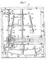
- the so-called carousel 10 shown in FIG. 1 has a central shaft 12, from which a whole series of elements are driven, which are described in detail below.
- An upper turntable 14, a middle turntable 16, a sprocket 18 and a lower turntable 20 are directly driven by this shaft from top to bottom.
- the sprocket 18 forms the carousel-side deflection area of a conveyor 22 which, as can be seen from FIG. 2 , is deflected at a point remote from the carousel by another sprocket 19 stored there.
- the conveyor 22 takes a straight line between the two sprockets (FIG. 3).
- a holder 24 which has at its upper end a shell 26 which is open at the bottom and radially expandable at the lower end and which tapers essentially towards the lower opening.
- a sleeve 28 is fastened on the side opposite the shell, ie in the direction of the shaft 12, which is displaceably guided on a guide rod 30 rigidly attached to the chain conveyor 22.
- a cam follower 32 At the bottom of the sleeve 28 there is a cam follower 32 in the form of a freely rotating roller which is guided in a stationary cam track 34.
- the trays and the holders move on a circular path, so that the trays 26 together with the holders 24 essentially on a vertical path - and be moved.
- the lower position is shown in solid lines and the upper position of the holder and a shell in dash-dotted lines.
- the plunger 40 can be moved up and down by means of the cylinder 36.
- the plunger is drawn out in Fig. 1 on the right side of the upper layer and shown in dashed lines on the left side in the upper layer.
- the lower position of the plunger 40 is shown in solid lines, provided that these parts are not covered by the shell.
- the cylinder 36, together with the piston rod 38 and the plunger 40, is oriented at an angle with respect to the plane of the central turntable 16, which is arranged perpendicular to the shaft axis, such that at least in the actual insertion area of the innards into the body cavity of a chicken, which insertion area is on a Circular path lies, the direction of movement of the plunger 40 in the center of the associated shell 26.
- FIG. 1 On the left side of FIG. 1, the parts described above are shown in solid lines in the position in which the shell is inserted into the body cavity of a chicken, not shown, and the pouch containing the innards, which was previously placed in the shell, is already in the body cavity of the chicken is inserted.
- a number of pressure elements 42 are articulated on the lower turntable 20 in such a way that they can be pivoted about an axis parallel and tangential to the plane of the turntable 20 such that these pressure elements 42 in the insertion area of the Offal into the body cavity of the chicken can be pressed during the movement on a circular path in the direction of the chicken.
- the pressing element 42 has a tilting rod 44 which is provided with a cam follower 48 designed as a roller at the end opposite the axis 46 mentioned.
- On the rocker arm 44 is a pressure member 55, which is shown on the left side of FIG. 1 in the position pressed against the chicken, not shown.
- the cam follower 48 follows a stationary cam track 56 to effect the pivoting movement of the rocker arm 44.
- control valve 60 On the upper turntable 14 there is at least one control valve 60, via which the respective cylinder 36 is controlled.
- This control valve 60 is connected to a photo-optically operated control device 62, which actuates the valve whenever a chicken is photo-optically detected, which is brought to the insertion area via an additional conveyor 64.
- the operation of the device described above is as follows:
- the chickens are continuously suspended from the legs by the conveyor 64 and conveyed to the insertion area for the offal into the chicken.
- innards packed in bags with the above-mentioned shells 26 are brought into the insertion area.
- the bags are introduced into the trays in the straight section of an essentially oval course of the conveyor 22.
- both the chickens and the trays and also the pestles move in a circular path.
- the pressing element 42 which also moves on a circular path, is pressed against the chicken.
- a bowl 26 is moved downward and introduced into the body cavity of the chicken brought up by the conveyor 64.
- the expansion element 58 slides between the legs of the chicken and facilitates the insertion of the shell 26.
- the holder 24 of the shell 26 forms a counterpressure surface for the chicken with a section 66 bent towards the pressure element 42.
- the plunger 40 is consequently moved in the previously indicated direction by means of the pneumatic cylinder 36 in order to insert the bag with the offal into the body cavity of the chicken .
- the initially essentially closed lower end of the shell spreads outwards as a result of its flexibility.
- the individual parts are then successively brought back to their starting position either as a result of the forced control by the cam curves or the special drive of the pneumatic cylinders.
- the chicken is then transported behind the carousel area.
- the plunger is also not actuated.
- the bowl thus moves downwards without the bag being ejected from the bowl. If this tray with the offal bag passes by the operator who fills the trays with the offal bags, this tray does not have to be filled in the given row. But it is also avoided that a bag is pushed out of the bowl without it falling into a chicken.
- the stabilization devices mentioned promote the automatic operation of the entire system.
- the plunger 40 consists of two sections 41 and 41 ', of which the front section 41' in the direction of insertion has a smaller diameter than the rear section 41.
- the diameters are dimensioned such that when the plunger is moved relatively rapidly downwards, preferably at a speed of at least 1 m / s, first the blunt end face of the section with the smaller diameter hitting the offal. Shortly after this section hits the giblets, the section of larger diameter abuts against the inner wall of the respective cup, which has already been inserted into the body cavity of the chicken, together with the chicken walls to the outside, so that this spreading force does not pass through the giblets onto the cup and the chicken has to be transferred.
- the cups 26 and plungers 40, together with the associated piston rod are arranged at an angle to the drive shaft 12 and the chickens hanging vertically downward such that the innards move towards the inner wall of the back of the chicken and essentially along this wall into the Body cavity are introduced.
Landscapes
- Life Sciences & Earth Sciences (AREA)
- Engineering & Computer Science (AREA)
- Wood Science & Technology (AREA)
- Zoology (AREA)
- Food Science & Technology (AREA)
- Meat, Egg Or Seafood Products (AREA)
- Processing Of Meat And Fish (AREA)
Applications Claiming Priority (2)
| Application Number | Priority Date | Filing Date | Title |
|---|---|---|---|
| DE3144178 | 1981-11-06 | ||
| DE19813144178 DE3144178A1 (de) | 1981-11-06 | 1981-11-06 | Vorrichtung zum einbringen von haehncheninnereien in die koerperhoehle von haehnchen |
Publications (2)
| Publication Number | Publication Date |
|---|---|
| EP0079051A1 EP0079051A1 (de) | 1983-05-18 |
| EP0079051B1 true EP0079051B1 (de) | 1986-04-23 |
Family
ID=6145821
Family Applications (1)
| Application Number | Title | Priority Date | Filing Date |
|---|---|---|---|
| EP82110160A Expired EP0079051B1 (de) | 1981-11-06 | 1982-11-04 | Vorrichtung zum Einbringen von Hähncheninnereien in die Körperhöhle von Hähnchen |
Country Status (4)
| Country | Link |
|---|---|
| US (1) | US4506410A (da) |
| EP (1) | EP0079051B1 (da) |
| DE (2) | DE3144178A1 (da) |
| DK (1) | DK155413C (da) |
Families Citing this family (2)
| Publication number | Priority date | Publication date | Assignee | Title |
|---|---|---|---|---|
| US5482503A (en) * | 1995-01-18 | 1996-01-09 | Baader North America Corporation | Apparatus for washing poultry carcasses |
| NL1017788C2 (nl) * | 2001-04-06 | 2002-10-08 | Meyn Food Proc Technology Bv | Inrichting en werkwijze voor het uitvoeren van een reinigingsbewerking op de inwendige halshuid van geslacht gevogelte. |
Family Cites Families (6)
| Publication number | Priority date | Publication date | Assignee | Title |
|---|---|---|---|---|
| US3540074A (en) * | 1968-10-11 | 1970-11-17 | William J Lawson | Giblet inserter |
| US3806988A (en) * | 1972-02-24 | 1974-04-30 | Gainesville Machine Co Inc | Poultry processing method and apparatus |
| NL7713640A (nl) * | 1977-12-09 | 1979-06-12 | Moba Holding Barneveld Bv | Inrichting voor het verwerken van voorwerpen. |
| US4251901A (en) * | 1979-07-20 | 1981-02-24 | Holly Farms Poultry Industries, Inc. | Apparatus and method for splitting poultry breasts |
| US4283813A (en) * | 1979-12-03 | 1981-08-18 | Stork Gamco, Inc. | Poultry inspection apparatus and method |
| DE3015336C2 (de) * | 1980-04-22 | 1985-09-19 | Gebr. Stolle GmbH u. Co KG, 2849 Visbek | Verfahren und Vorrichtung zum Einbringen von aufbereiteten Innereien in ausgenommene Schlacht-Hähnchen |
-
1981
- 1981-11-06 DE DE19813144178 patent/DE3144178A1/de not_active Withdrawn
-
1982
- 1982-03-16 US US06/358,837 patent/US4506410A/en not_active Expired - Fee Related
- 1982-11-03 DK DK487482A patent/DK155413C/da not_active IP Right Cessation
- 1982-11-04 DE DE8282110160T patent/DE3270792D1/de not_active Expired
- 1982-11-04 EP EP82110160A patent/EP0079051B1/de not_active Expired
Also Published As
| Publication number | Publication date |
|---|---|
| US4506410A (en) | 1985-03-26 |
| DE3270792D1 (en) | 1986-05-28 |
| EP0079051A1 (de) | 1983-05-18 |
| DK155413C (da) | 1989-08-21 |
| DK155413B (da) | 1989-04-10 |
| DE3144178A1 (de) | 1983-05-19 |
| DK487482A (da) | 1983-05-07 |
Similar Documents
| Publication | Publication Date | Title |
|---|---|---|
| DE2214080C3 (de) | Vorrichtung zum sterilen Abfüllen von Nahrungs- und Genußmitteln | |
| EP0962143B1 (de) | Vorrichtung zum Herstellen von Würsten | |
| DE2510094A1 (de) | Vorrichtung fuer die veraenderung der anordnung von zigarettenpackungen waehrend ihres vorschubs | |
| DE1197803B (de) | Verfahren und Vorrichtung zum automatischen Verpacken von Suesswaren in Schachteln | |
| DE2747044C2 (de) | Verfahren und Vorrichtung zum Reinigen von Ampullen oder ähnlichen Behältnissen | |
| DE4419488A1 (de) | Vorrichtung zum Wiegen von Hartgelatinekapseln | |
| DE3631891C2 (de) | Vorrichtung zum Überführen von ungefüllten Verpackungstuben | |
| DE2522970B2 (de) | Vorrichtung zum Zuführen von abgelängten Drähten zu einer Drahtverarbeitungsmaschine, insbesondere einer Gitterschweißmaschine | |
| EP0079051B1 (de) | Vorrichtung zum Einbringen von Hähncheninnereien in die Körperhöhle von Hähnchen | |
| EP2388112B1 (de) | Verfahren und Vorrichtung zum Aufnehmen, Verlagern und Ablegen von Portionen eines Lebensmittels | |
| DE2804191C2 (de) | Verfahren und Vorrichtung zum Herstellen von Würstchen-in-Lake-Beuteln | |
| DE489264C (de) | Mit Vor- und Nachfuellung arbeitende Auswiege- und Einfuellvorrichtung, insbesondere fuer Makkaroni und aehnliches stangenfoermiges Gut | |
| DE3015336C2 (de) | Verfahren und Vorrichtung zum Einbringen von aufbereiteten Innereien in ausgenommene Schlacht-Hähnchen | |
| DE2001932C3 (de) | Vorrichtung zum Transportieren von Stranggut | |
| DE3108912C2 (de) | Verfahren zur Entfernung loser Partikel aus Bechern und Vorrichtung zur Durchführung des Verfahrens | |
| DE69414961T2 (de) | Vorrichtung zum Füllen essbarer, stabförmiger, hohler Körper mit Schokolade | |
| DE4111786A1 (de) | Verfahren und vorrichtung zum herstellen von beutelartigen packungen fuer insbesondere kautabakersatz | |
| DE1531968B2 (de) | Vorrichtung zum abgeben von im wesentlichen zylindrischen gegenstaenden in axialer ausrichtung | |
| DE2209997C3 (de) | Vorrichtung zum Aufrichten und Füllen von Kartonbehältern mit Verpackungen | |
| DE2740820C2 (de) | Vorrichtung zum Auffangen von Fischen an einer Zuführstelle | |
| DE29508934U1 (de) | Abfüllvorrichtung zum Abfüllen von Spermaflüssigkeit | |
| DE3885672T2 (de) | Behälterfüllsystem. | |
| DE1586311C3 (da) | ||
| DE19728402C2 (de) | Vorrichtung zum Ausrichten von zylindrischen Gegenständen | |
| DE4224432C1 (de) | Schlauchbeutel-Packer |
Legal Events
| Date | Code | Title | Description |
|---|---|---|---|
| PUAI | Public reference made under article 153(3) epc to a published international application that has entered the european phase |
Free format text: ORIGINAL CODE: 0009012 |
|
| AK | Designated contracting states |
Designated state(s): DE FR GB IT NL SE |
|
| 17P | Request for examination filed |
Effective date: 19831118 |
|
| ITF | It: translation for a ep patent filed | ||
| GRAA | (expected) grant |
Free format text: ORIGINAL CODE: 0009210 |
|
| AK | Designated contracting states |
Kind code of ref document: B1 Designated state(s): DE FR GB IT NL SE |
|
| ET | Fr: translation filed | ||
| REF | Corresponds to: |
Ref document number: 3270792 Country of ref document: DE Date of ref document: 19860528 |
|
| PLBE | No opposition filed within time limit |
Free format text: ORIGINAL CODE: 0009261 |
|
| STAA | Information on the status of an ep patent application or granted ep patent |
Free format text: STATUS: NO OPPOSITION FILED WITHIN TIME LIMIT |
|
| 26N | No opposition filed | ||
| NLS | Nl: assignments of ep-patents |
Owner name: STORK PMT B.V. TE BOXMEER. |
|
| REG | Reference to a national code |
Ref country code: FR Ref legal event code: TP |
|
| PGFP | Annual fee paid to national office [announced via postgrant information from national office to epo] |
Ref country code: FR Payment date: 19891030 Year of fee payment: 8 |
|
| PGFP | Annual fee paid to national office [announced via postgrant information from national office to epo] |
Ref country code: GB Payment date: 19891031 Year of fee payment: 8 |
|
| PGFP | Annual fee paid to national office [announced via postgrant information from national office to epo] |
Ref country code: SE Payment date: 19891121 Year of fee payment: 8 |
|
| PGFP | Annual fee paid to national office [announced via postgrant information from national office to epo] |
Ref country code: DE Payment date: 19891128 Year of fee payment: 8 |
|
| ITTA | It: last paid annual fee | ||
| PGFP | Annual fee paid to national office [announced via postgrant information from national office to epo] |
Ref country code: NL Payment date: 19891130 Year of fee payment: 8 |
|
| PG25 | Lapsed in a contracting state [announced via postgrant information from national office to epo] |
Ref country code: GB Effective date: 19901104 |
|
| PG25 | Lapsed in a contracting state [announced via postgrant information from national office to epo] |
Ref country code: SE Effective date: 19901105 |
|
| PG25 | Lapsed in a contracting state [announced via postgrant information from national office to epo] |
Ref country code: NL Effective date: 19910601 |
|
| GBPC | Gb: european patent ceased through non-payment of renewal fee | ||
| NLV4 | Nl: lapsed or anulled due to non-payment of the annual fee | ||
| PG25 | Lapsed in a contracting state [announced via postgrant information from national office to epo] |
Ref country code: FR Effective date: 19910731 |
|
| PG25 | Lapsed in a contracting state [announced via postgrant information from national office to epo] |
Ref country code: DE Effective date: 19910801 |
|
| REG | Reference to a national code |
Ref country code: FR Ref legal event code: ST |
|
| EUG | Se: european patent has lapsed |
Ref document number: 82110160.7 Effective date: 19910705 |