EP0079240A2 - Procédé de revêtement par pulvérisation de boîtes à fond fermé - Google Patents
Procédé de revêtement par pulvérisation de boîtes à fond fermé Download PDFInfo
- Publication number
- EP0079240A2 EP0079240A2 EP82305966A EP82305966A EP0079240A2 EP 0079240 A2 EP0079240 A2 EP 0079240A2 EP 82305966 A EP82305966 A EP 82305966A EP 82305966 A EP82305966 A EP 82305966A EP 0079240 A2 EP0079240 A2 EP 0079240A2
- Authority
- EP
- European Patent Office
- Prior art keywords
- nozzle
- spraying
- side wall
- section
- centre line
- Prior art date
- Legal status (The legal status is an assumption and is not a legal conclusion. Google has not performed a legal analysis and makes no representation as to the accuracy of the status listed.)
- Granted
Links
Images

Classifications
-
- B—PERFORMING OPERATIONS; TRANSPORTING
- B05—SPRAYING OR ATOMISING IN GENERAL; APPLYING FLUENT MATERIALS TO SURFACES, IN GENERAL
- B05D—PROCESSES FOR APPLYING FLUENT MATERIALS TO SURFACES, IN GENERAL
- B05D1/00—Processes for applying liquids or other fluent materials
- B05D1/02—Processes for applying liquids or other fluent materials performed by spraying
-
- B—PERFORMING OPERATIONS; TRANSPORTING
- B05—SPRAYING OR ATOMISING IN GENERAL; APPLYING FLUENT MATERIALS TO SURFACES, IN GENERAL
- B05B—SPRAYING APPARATUS; ATOMISING APPARATUS; NOZZLES
- B05B13/00—Machines or plants for applying liquids or other fluent materials to surfaces of objects or other work by spraying, not covered by groups B05B1/00 - B05B11/00
- B05B13/06—Machines or plants for applying liquids or other fluent materials to surfaces of objects or other work by spraying, not covered by groups B05B1/00 - B05B11/00 specially designed for treating the inside of hollow bodies
- B05B13/0627—Arrangements of nozzles or spray heads specially adapted for treating the inside of hollow bodies
-
- B—PERFORMING OPERATIONS; TRANSPORTING
- B05—SPRAYING OR ATOMISING IN GENERAL; APPLYING FLUENT MATERIALS TO SURFACES, IN GENERAL
- B05D—PROCESSES FOR APPLYING FLUENT MATERIALS TO SURFACES, IN GENERAL
- B05D7/00—Processes, other than flocking, specially adapted for applying liquids or other fluent materials to particular surfaces or for applying particular liquids or other fluent materials
- B05D7/22—Processes, other than flocking, specially adapted for applying liquids or other fluent materials to particular surfaces or for applying particular liquids or other fluent materials to internal surfaces, e.g. of tubes
- B05D7/227—Processes, other than flocking, specially adapted for applying liquids or other fluent materials to particular surfaces or for applying particular liquids or other fluent materials to internal surfaces, e.g. of tubes of containers, cans or the like
Definitions
- This invention relates to method and apparatus for coating the interior of metal cans, and more particularly, to an improved method and apparatus for applying a uniform coating to the interior surface of a cylindrical can body having only one open end.
- metal cans are made in either two pieces or in three pieces.
- a two piece can is made by deep drawing a cylinder with a closed end and then closing the cylinder with a can end.
- Three piece cans so-called comprise open ended cylindrical shell bodies to which separate top and bottom ends are secured.
- the invention of this application is concerned only with coating of two piece cans, i.e.,those which are made from a deep drawn cylinder having a closed end.
- This nozzle is oriented with respect to the can so that the maximum flow of coating material is directed axially the length of the can and the fan shaped pattern is directed toward the radius of the can bottom and one longitudinal line on the side wall. This procedure results in a substantially uniform coating being applied over the side wall of the can; the distribution of the spray fan compensating for the increased distance the paint has to travel from the open to the closed end of the can.
- Low solids coating materials are defined as those which contain generally 15% to 25% of solids relative to liquid solvent carriers. When the coating is cured only 15% to 25% of the original weight of coating material remains after the solvents are driven off.
- the invention is based upon the discovery that high solids or higher solids liquid coating materials may be satisfactorily applied to two piece can bodies by utilising two nozzles to apply the coating material.
- One of these nozzles is operative to spray the lower portion of the cylindrical side wall of the can body as well as the reverse wall section of the bottom of the can body as well as the reverse wall section of the bottom of the can body while the other nozzle sprays the top portion of the side wall and the crown or centre section of the bottom wall.
- This spray pattern reduces the need to bounce spray off of the lower cylindrical section of the body in order to adequately coat the reverse wall section and enables that section to be coated with a minimum of material.
- this spray technique and/or process has been found to result in a much more uniform coating of the interior of the can body than has heretofore been possible with even low solids material.
- this invention enables the spray material to be applied more evenly to the can body than has heretofore been possible.
- a lesser total quantity of material may be used to effect complete coverage of the inside surface of the can since it is no longer necessary to apply excess material to some areas of the can body in order to obtain minimum coverage of selected hard to get at areas.
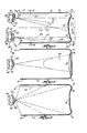
- FIG. 1 to 3 there is illustrated a two piece can 10 of the type which is coated by the practice of this invention. It is referred to as a two piece can because it is drawn from a single blank of metal which forms the bottom wall 11 and side wall 12 from a single piece of metal.
- the second piece in this .type of two piece can is a can end which is applied to the open end 13 after the can has been coated according to the practice of the invention and has been filled with food or beverage contents.
- the can body 10 comprises the cylindrical side wall 12 and a bottom crown section 14. These two sections 12 and 14 are interconnected by a radiused well section 15 and a reverse wall section 16.
- the reverse wall section 16 generally extends parallel to the side wall 12 and is the section of can body which is particularly difficult to coat utilising can coating techniques of the type commonly in use prior to the invention of this application.
- FIG. 1 it will be seen that there are two airless spray nozzles 20, 21 directed through the open top 13 of the can.
- One of these nozzles 20 is operative to spray the inner section 22 of the side wall 12, the well section 15 of the bottom wall, the reverse wall section 16 of the bottom wall, and a very small portion 23 of the crown section 14 of the bottom wall.
- the other nozzle 21 is operative to spray the crown section 14 of the bottom wall and the outermost portion 24 of the side wall.
- the nozzle 21 also is operative to spray to a lesser extent the inner portion 22 of the side wall as well as the well section and reverse wall section of the bottom 14. The heaviest portion of the spray from the nozzle 21 though is directed at the outer portion 24 of the side wall 12 and the crown section 14 of the bottom wall.
- the fan shaped spray patterns 26 and 27 from the nozzles 20 and 21 respectively are located on cordal planes 28, 29 of the can body rather than diametral planes as has heretofore been common practice in the coating of two piece cans. It will also be noted that these two cordal planes extend parallel to one another so that the two spray patterns emitted from the nozzles 20, 21 even though sprayed simultaneously do not impinge upon one another.
- centre line 30 of the spray pattern 26 extends at a 4° angle relative to the centre line 31 of the can body 10. It will also be noted that the centre line 32 of the spray pattern 27 emitted from the nozzle 21 extends at a 7 0 angle to the centre line 31 of the can body.
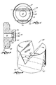
- FIG. 5 and 6 there is illustrated a nozzle holder 35 and a nozzle tip 36 employed in the- practice of this invention. Since the nozzle holder and nozzle tip 35 and 36 are substantially identical in the nozzles 20 and 21 except for dimensional differences as described more fully hereinafter, only one nozzle holder and nozzle tip will be described in detail herein. It should be appreciated though that a substantially identical nozzle holder and nozzle tip differing only in dimensions are employed in the other nozzle.
- the nozzle holder 35 is secured onto the outlet end 40 of a conventional dispensing gun by a threaded nut 41.
- This nut 41 has a collar 42 which engages a shoulder 43 of the holder 35 and secures it to the outer end 40 of the gun in a sealed relationship.
- the nozzle tip 36 is manufactured from a very small slug of sintered metal or sintered carbide.
- This sintered slug is cross cut by two intersecting slots 47, 48, the first slot 47 is located on the back.side of the tip and the other slot 48 is located on the front side of the tip.
- the two slots are offset from one another by 90°.
- Each slot extends approximately one-half the thickness of the slug but at least one of the two is sufficiently deep that it intersects the other slot.
- Both slots are cut by a grinding wheel having a V-shaped peripheral edge.
- the back side groove 47 of the tip 36 within that nozzle is cut by a grinding wheel defining an included angle of 40° with the result that the slot 47 also defines an included angle ⁇ of 40°.
- the front slot of nozzle tip 36 in the nozzle 21 is cut with a grinding wheel defining an included angle ⁇ of 25 0 .
- the intersection of the two intersecting grooves define an orifice 50 which is .008 (0.02 cm) wide and .008 (0.02 cm) long, and this nozzle has a flow rate of 42.1 grams per minute of water at 40 pounds per square inch (2.74 x 10 Nm ) gauge.
- the other nozzle tip 36 contained with the the nozzle 20 has a back side groove defining an included' angle ⁇ of 50 0 and a front side groove which also defines an included angle ⁇ of 50 0.
- the grooves of this nozzle 21 are cut to a depth such that the orifice 50 of the nozzle tip is .004" (0.01 cm) wide by .006" ( 0 .015 cm) long.
- This nozzle has a flow rate of 15.6 grams per minute of water at 40 pounds per square inch (2.74 x 10 5 Nm -2 ) gauge.
- the can body 10 is mounted upon a conventional can coating machine having multiple rotatable heads 55 for the reception of the can bodies. These heads 55 are indexable through multiple stationsand at one station 56 align the can bodies 10 in front of the nozzles 20, 21 as illustrated in Figures 1 to 3. At this station 56 the axis 31 of the can body is located in a horizontal plane and the can is rotated by the head 55 at a preset speed. During this rotation of the can body 10 at the coating station 56, liquid supplied to the dispensing gun 40, 41 at a relatively high pressure, is ejected from the nozzles 20, 21 for a predetermined short duration of time. This high pressure liquid emergesifrom the nozzle tip as an atomised spray in the patterns 26, 27 described hereinabove.
- a valve internally of the gun 4 0 , 41 is closed and liquid spray from the nozzles is terminated.
- the can supporting heads 55 are then indexed and a new uncoated can moved before the fixedly mounted nozzles as is conventional in such can coating machines.
- the nozzle orifice was placed a distance d 1 of 15 millimetres from the open end of the can body 10 and a distance d 2 of 12 millimetres from the side wall of the can.
- the can body was sprayed by this nozzle for 30 milliseconds while the can body was rotated at 1950 revolutions per minute (RPM). This time represents approximately one full revolution of the can body.
- the other nozzle 20 was placed 18 millimetres from one side wall of the can. This nozzle applied spray to the can body for 150 milliseconds during this test.
- the liquid sprayed from both nozzles during this test was formulated as follows:
- This liquid was supplied to the nozzles at 185°F. (85°C) at a pressure of 850 pounds per square inch (5.82 x 10 Nm ) gauge.
- the results of this test were that 156 milligrams of dry coating material were applied to the interior of the can. This is the weight of the sprayed material after the can had been removed from the coating machine and the solvents driven out of the sprayed material.
- This dry coating represented 65% of the weight of the coating when measured on the can wet, meaning that the coating was 65% solids in the wet condition.
- the second test can No. 2 the conditions were the same as for the first test can No. 1 except that the spraying times were varied. As a result only 128 milligrams of cured coating material was applied to the can. This can, when tested with a conventional Waco tester, was found to measure only two milliamps.
- the thicknesses of material Prior to this invention it has been common to measure the thicknesses of material over the surface area of the can. In general, substantially greater thicknesses of coating have been found to have been applied to the can side walls than was required in order to obtain minimum coverage of the reverse wall 16 section of the can bottom. According to the practice of this invention though, and as evidenced by the four tests described in the chart, the can coating is very even, and even though it is substantially reduced from the first to the fourth test there is very little difference in the amount of current passed through the can coating. Furthermore, the practice of this invention for the first time enables a high solids content liquid to be utilised in the interior surface of a two piece can.
Landscapes
- Life Sciences & Earth Sciences (AREA)
- Engineering & Computer Science (AREA)
- Wood Science & Technology (AREA)
- Application Of Or Painting With Fluid Materials (AREA)
- Spray Control Apparatus (AREA)
Applications Claiming Priority (2)
| Application Number | Priority Date | Filing Date | Title |
|---|---|---|---|
| US06/319,587 US4378386A (en) | 1981-11-09 | 1981-11-09 | Method of spraying closed end cans |
| US319587 | 1981-11-09 |
Publications (3)
| Publication Number | Publication Date |
|---|---|
| EP0079240A2 true EP0079240A2 (fr) | 1983-05-18 |
| EP0079240A3 EP0079240A3 (en) | 1984-05-30 |
| EP0079240B1 EP0079240B1 (fr) | 1986-11-12 |
Family
ID=23242885
Family Applications (1)
| Application Number | Title | Priority Date | Filing Date |
|---|---|---|---|
| EP82305966A Expired EP0079240B1 (fr) | 1981-11-09 | 1982-11-09 | Procédé de revêtement par pulvérisation de boîtes à fond fermé |
Country Status (5)
| Country | Link |
|---|---|
| US (1) | US4378386A (fr) |
| EP (1) | EP0079240B1 (fr) |
| JP (1) | JPS58128166A (fr) |
| CA (1) | CA1197149A (fr) |
| DE (1) | DE3274198D1 (fr) |
Families Citing this family (20)
| Publication number | Priority date | Publication date | Assignee | Title |
|---|---|---|---|---|
| US4663195A (en) * | 1984-08-15 | 1987-05-05 | Nordson Corporation | Continuous coating process for discrete articles |
| US4615296A (en) * | 1984-08-15 | 1986-10-07 | Nordson Corporation | Continuous coating system for discrete articles |
| JPS6238269A (ja) * | 1985-08-13 | 1987-02-19 | Nordson Kk | エアレススプレイ塗布方法 |
| US4904505A (en) * | 1988-03-18 | 1990-02-27 | Armco Inc. | Lubricant mist coating of metal sheet |
| US4987001A (en) * | 1989-02-09 | 1991-01-22 | Nordson Corporation | Method and apparatus for coating the interior surface of hollow, tubular articles |
| US5232739A (en) * | 1990-10-15 | 1993-08-03 | Ball Corporation | Dual orifice nozzle and method for internally coating containers |
| US5366162A (en) * | 1990-10-15 | 1994-11-22 | Ball Corporation | Dual orifice nozzle and method for internally coating containers |
| US5096746A (en) * | 1990-10-15 | 1992-03-17 | Ball Corporation | Dual orifice nozzle and method for interally coating containers |
| US5344073A (en) * | 1992-04-29 | 1994-09-06 | Nordson Corporation | Nozzle cleaning system including spray gun cover for can coating system |
| DE19538340A1 (de) * | 1995-10-14 | 1997-04-17 | Basf Lacke & Farben | Verfahren und Vorrichtung zum Aufbringen von Spritzlacken auf die Innenoberfläche von einseitig offenen Emballagen sowie die entsprechenden innenlackierten Emballagen |
| US5941456A (en) * | 1997-06-17 | 1999-08-24 | Nordson Corporation | Nozzle cleaning system including coating spray gun cover for can coating system |
| KR20010038260A (ko) * | 1999-10-23 | 2001-05-15 | 이구택 | 2피스 스틸캔 내면에 피막을 형성하는 방법 |
| JP2005525236A (ja) | 2002-05-13 | 2005-08-25 | ノードソン コーポレーション | スプレー装置において表面の回転速度を検出する装置及び方法 |
| AU2003285027A1 (en) * | 2002-10-28 | 2004-05-25 | Thomas E. Hollstein | Can lid score repair with uv curable material |
| JP4515192B2 (ja) * | 2004-08-04 | 2010-07-28 | ユニバーサル製缶株式会社 | 缶本体の内面塗装方法 |
| WO2007133386A2 (fr) | 2006-05-09 | 2007-11-22 | Nordson Corporation | Système de commande pour l'application de revêtement sur des boîtes |
| US8545937B2 (en) * | 2009-08-31 | 2013-10-01 | Nordson Corporation | Spray coating with uniform flow distribution |
| US9889460B2 (en) | 2014-09-11 | 2018-02-13 | Verticon, Llc | Continuous vertical spraying of bodies such as cans |
| WO2019049614A1 (fr) * | 2017-09-07 | 2019-03-14 | 株式会社Ihi | Dispositif de revêtement d'un cylindre |
| CN111822309A (zh) * | 2019-04-23 | 2020-10-27 | 奥瑞金科技股份有限公司 | 一种两片罐及其加工方法 |
Family Cites Families (6)
| Publication number | Priority date | Publication date | Assignee | Title |
|---|---|---|---|---|
| US3697313A (en) * | 1970-02-24 | 1972-10-10 | Nordson Corp | Method of spraying closed end cans |
| US3693828A (en) * | 1970-07-22 | 1972-09-26 | Crown Cork & Seal Co | Seamless steel containers |
| US3843055A (en) * | 1973-07-18 | 1974-10-22 | Nordson Corp | Spray nozzle |
| JPS51124141A (en) * | 1975-04-22 | 1976-10-29 | Nordson Corp | Method of coating inner surface of can and the like |
| US4186225A (en) * | 1976-08-04 | 1980-01-29 | American Can Company | Method of coating the interior surfaces of a hollow article |
| US4278709A (en) * | 1979-10-25 | 1981-07-14 | Ball Corporation | Method of applying water soluble internal coating to hot cans |
-
1981
- 1981-11-09 US US06/319,587 patent/US4378386A/en not_active Expired - Lifetime
-
1982
- 1982-10-29 CA CA000414458A patent/CA1197149A/fr not_active Expired
- 1982-11-09 EP EP82305966A patent/EP0079240B1/fr not_active Expired
- 1982-11-09 DE DE8282305966T patent/DE3274198D1/de not_active Expired
- 1982-11-09 JP JP57195406A patent/JPS58128166A/ja active Granted
Also Published As
| Publication number | Publication date |
|---|---|
| DE3274198D1 (en) | 1987-01-02 |
| JPS58128166A (ja) | 1983-07-30 |
| US4378386A (en) | 1983-03-29 |
| EP0079240A3 (en) | 1984-05-30 |
| CA1197149A (fr) | 1985-11-26 |
| JPH0361507B2 (fr) | 1991-09-20 |
| EP0079240B1 (fr) | 1986-11-12 |
Similar Documents
| Publication | Publication Date | Title |
|---|---|---|
| EP0079240B1 (fr) | Procédé de revêtement par pulvérisation de boîtes à fond fermé | |
| US3697313A (en) | Method of spraying closed end cans | |
| US5571575A (en) | Laser shock method utilizing light absorbing material | |
| US3843055A (en) | Spray nozzle | |
| US3737108A (en) | Spray nozzle | |
| US5096746A (en) | Dual orifice nozzle and method for interally coating containers | |
| RU2637028C2 (ru) | Колоколообразная насадка для устройства электростатического нанесения покрытия методом центробежного распыления | |
| US5636795A (en) | Cyclonic spray nozzle | |
| JPH06210199A (ja) | 粉体コーティング・ガン用の整形スプレ・ノズル | |
| US4025664A (en) | Container coating method | |
| US4183974A (en) | Container coating method | |
| CA1094404A (fr) | Methode de protection contre la rouille | |
| US3797456A (en) | Apparatus for coating the interiors of hollow bodies | |
| CA1062095A (fr) | Methode de revetement des bouteilles par pulverisation | |
| US4150164A (en) | Process for heating cylindrical containers with a plasma arc generated flame | |
| EP0347058A2 (fr) | Méthode d'application d'une couche isolante imperméable à l'humidité sur un circuit imprimé | |
| JPH0437743B2 (fr) | ||
| US5232739A (en) | Dual orifice nozzle and method for internally coating containers | |
| US5366162A (en) | Dual orifice nozzle and method for internally coating containers | |
| WO2011025653A1 (fr) | Revêtement par vaporisation à répartition de flux uniforme | |
| KR102074870B1 (ko) | 분체 도장 장치 | |
| US4278709A (en) | Method of applying water soluble internal coating to hot cans | |
| US4420511A (en) | Method for coating an object | |
| CA1194290A (fr) | Systeme d'enduction d'objets, telles des bouteilles en verre, avec une matiere synthetique | |
| JPH02502524A (ja) | 回転体の形状をなす製品に塗料を熱ガススプレー付着する装置 |
Legal Events
| Date | Code | Title | Description |
|---|---|---|---|
| PUAI | Public reference made under article 153(3) epc to a published international application that has entered the european phase |
Free format text: ORIGINAL CODE: 0009012 |
|
| AK | Designated contracting states |
Designated state(s): DE FR GB NL |
|
| PUAL | Search report despatched |
Free format text: ORIGINAL CODE: 0009013 |
|
| RHK1 | Main classification (correction) |
Ipc: B05B 13/02 |
|
| AK | Designated contracting states |
Designated state(s): DE FR GB NL |
|
| RHK1 | Main classification (correction) |
Ipc: B05B 13/06 |
|
| 17P | Request for examination filed |
Effective date: 19840828 |
|
| GRAA | (expected) grant |
Free format text: ORIGINAL CODE: 0009210 |
|
| AK | Designated contracting states |
Kind code of ref document: B1 Designated state(s): DE FR GB NL |
|
| REF | Corresponds to: |
Ref document number: 3274198 Country of ref document: DE Date of ref document: 19870102 |
|
| ET | Fr: translation filed | ||
| PLBE | No opposition filed within time limit |
Free format text: ORIGINAL CODE: 0009261 |
|
| STAA | Information on the status of an ep patent application or granted ep patent |
Free format text: STATUS: NO OPPOSITION FILED WITHIN TIME LIMIT |
|
| 26N | No opposition filed | ||
| PGFP | Annual fee paid to national office [announced via postgrant information from national office to epo] |
Ref country code: NL Payment date: 19971021 Year of fee payment: 16 |
|
| PG25 | Lapsed in a contracting state [announced via postgrant information from national office to epo] |
Ref country code: NL Free format text: LAPSE BECAUSE OF NON-PAYMENT OF DUE FEES Effective date: 19990601 |
|
| NLV4 | Nl: lapsed or anulled due to non-payment of the annual fee |
Effective date: 19990601 |
|
| PGFP | Annual fee paid to national office [announced via postgrant information from national office to epo] |
Ref country code: GB Payment date: 20001024 Year of fee payment: 19 |
|
| PGFP | Annual fee paid to national office [announced via postgrant information from national office to epo] |
Ref country code: DE Payment date: 20001026 Year of fee payment: 19 |
|
| PGFP | Annual fee paid to national office [announced via postgrant information from national office to epo] |
Ref country code: FR Payment date: 20001027 Year of fee payment: 19 |
|
| PG25 | Lapsed in a contracting state [announced via postgrant information from national office to epo] |
Ref country code: GB Free format text: LAPSE BECAUSE OF NON-PAYMENT OF DUE FEES Effective date: 20011109 |
|
| REG | Reference to a national code |
Ref country code: GB Ref legal event code: IF02 |
|
| GBPC | Gb: european patent ceased through non-payment of renewal fee |
Effective date: 20011109 |
|
| PG25 | Lapsed in a contracting state [announced via postgrant information from national office to epo] |
Ref country code: DE Free format text: LAPSE BECAUSE OF NON-PAYMENT OF DUE FEES Effective date: 20020702 |
|
| PG25 | Lapsed in a contracting state [announced via postgrant information from national office to epo] |
Ref country code: FR Free format text: LAPSE BECAUSE OF NON-PAYMENT OF DUE FEES Effective date: 20020730 |
|
| REG | Reference to a national code |
Ref country code: FR Ref legal event code: ST |
|
| REG | Reference to a national code |
Ref country code: FR Ref legal event code: ST |