EP0079305A2 - Vorrichtung zur Messung des Blutdrucks - Google Patents
Vorrichtung zur Messung des Blutdrucks Download PDFInfo
- Publication number
- EP0079305A2 EP0079305A2 EP82810446A EP82810446A EP0079305A2 EP 0079305 A2 EP0079305 A2 EP 0079305A2 EP 82810446 A EP82810446 A EP 82810446A EP 82810446 A EP82810446 A EP 82810446A EP 0079305 A2 EP0079305 A2 EP 0079305A2
- Authority
- EP
- European Patent Office
- Prior art keywords
- pressure
- chamber
- systolic
- diastolic
- range
- Prior art date
- Legal status (The legal status is an assumption and is not a legal conclusion. Google has not performed a legal analysis and makes no representation as to the accuracy of the status listed.)
- Granted
Links
Images


Classifications
-
- A—HUMAN NECESSITIES
- A61—MEDICAL OR VETERINARY SCIENCE; HYGIENE
- A61B—DIAGNOSIS; SURGERY; IDENTIFICATION
- A61B5/00—Measuring for diagnostic purposes; Identification of persons
- A61B5/02—Detecting, measuring or recording for evaluating the cardiovascular system, e.g. pulse, heart rate, blood pressure or blood flow
- A61B5/021—Measuring pressure in heart or blood vessels
- A61B5/022—Measuring pressure in heart or blood vessels by applying pressure to close blood vessels, e.g. against the skin; Ophthalmodynamometers
- A61B5/02208—Measuring pressure in heart or blood vessels by applying pressure to close blood vessels, e.g. against the skin; Ophthalmodynamometers using the Korotkoff method
-
- A—HUMAN NECESSITIES
- A61—MEDICAL OR VETERINARY SCIENCE; HYGIENE
- A61B—DIAGNOSIS; SURGERY; IDENTIFICATION
- A61B5/00—Measuring for diagnostic purposes; Identification of persons
- A61B5/02—Detecting, measuring or recording for evaluating the cardiovascular system, e.g. pulse, heart rate, blood pressure or blood flow
- A61B5/021—Measuring pressure in heart or blood vessels
- A61B5/022—Measuring pressure in heart or blood vessels by applying pressure to close blood vessels, e.g. against the skin; Ophthalmodynamometers
- A61B5/0225—Measuring pressure in heart or blood vessels by applying pressure to close blood vessels, e.g. against the skin; Ophthalmodynamometers the pressure being controlled by electric signals, e.g. derived from Korotkoff sounds
Definitions
- the present invention relates to a method for measuring the blood pressure of a subject using a device comprising a cuff intended to be fixed to a member of the subject and comprising a deformable chamber, which consists in introducing into the chamber and then extracting a gas therefrom, preferably air, so that the pressure in the chamber is changed at least in an area encompassing the subject's systolic and diastolic pressure.
- the object of the present invention is to provide a method for measuring blood pressure by which the time necessary for a measurement is made as short as possible while allowing high measurement accuracy to be obtained.
- a method of measuring blood pressure which consists, in a first step, in determining a range of systolic pressure comprising the systolic pressure and a range of diastolic pressure comprising the diastolic pressure, and, in a second step, varying the pressure of the gas in the deformable chamber again in at least part of these areas and determining the systolic pressure and the diastolic pressure during this second step.
- blood pressure and "chamber pressure” should be understood in the claims and in the description to be overpressures relative to the pressure of the ambient air.
- the blood pressure measuring device shown in FIG. 1 comprises a cuff 1 intended to be fixed to the arm of a subject and an apparatus designated as a whole with the reference 11.
- the cuff 1 comprises a chamber 3 in the form of a pocket of deformable and inflatable rubber, as well as a microphone 5.
- the chamber 3 and the microphone 5 are respectively connected to the device 11 by a flexible pipe 7 and by a flexible electrical cable 9 as well as, for example, by plug-in connectors .
- the device 11 includes a power supply device 39, which for example includes a battery or a power supply from the network, and which supplies the voltages necessary for the operation of the various electronic components of the device.
- the device 39 includes a switch 41 enabling the supply to be switched on and off.
- One of the terminals of the device 39 is also connected to the ground of the device 11.
- the apparatus 11 further comprises a pump 13 with a pump body, for example cylindrical, made of elastic material.
- Chamber 3 is connected to pump 13 via line 7, a line 7 'mounted in the apparatus as well as a non-return valve 15.
- An electrically controlled deflation valve 17 and a pressure sensor pressure 19 are also connected to line 7 '.
- the pump 13 further comprises an air inlet provided with a non-return valve 21.
- the two non-return valves 15 and 21 are connected so that, by pressing and releasing alternately and manually the pump body, ambient air either pumped into room 3.
- the pressure sensor 19 comprises for example a bridge circuit formed from piezoresistive elements. It delivers in operation a voltage proportional to the pressure in the chamber 3, and it is connected via an amplifier 27 to the input of an analog / digital converter 29.
- the latter comprises a control input and eight outputs connected to the control circuit.
- the analog / digital converter 29 converts the analog signal supplied to it by the amplifier 27 into an eight-bit digital signal and delivers this digital signal in parallel to the control circuit 25 in response to a signal supplied at its input. control by this control circuit 25.
- the device determines quickly and with relatively low accuracy the pressure ranges in which the systolic pressure, respectively the diastolic pressure, are found.
- the device determines the exact values of the systolic pressure and the diastolic pressure by making the pressure again go through the areas determined in the first step.
- Each measurement takes place according to a program determined by the control circuit and which will be described in more detail.
- the cuff 1 is fixed to a member of the subject, generally to one of his arms.
- the chamber 3 and the microphone 5 are connected to the device 11 if this connection is not already made.
- FIG. 2 The measurement sequence will now be described using FIG. 2.
- the upper part of this FIG. 2 represents the diagram of the variation as a function of time of the pressure p prevailing in the chamber 3 and measured by the sensor. pressure 19.
- the lower part of this figure 2 represents by a line vertical each pulse supplied by the pulse trainer 23 to the control circuit 25 in response to a Korotkoff noise.
- the first Korotkoff noise is detected by the microphone 5 at time t , so that the pulse trainer 23 delivers an impulse representing this noise from Korotkoff.
- the control circuit 25 commands a deflation jump in response to each Korotkoff noise detected by the microphone 5.
- each Korotkoff noise causes a reduction in the pressure in the chamber 3 d 'an amount equal to the predetermined amount d 1 .
- the instant at which the last Korotkoff noise is detected is designated by t 4 .
- the diastolic pressure of the subject is in the pressure range which extends from the pressure designated by p 3 to the pressure designated by p 4 in FIG. 2. This range will be designated subsequently as the diastolic pressure range I D.
- the pressure p 3 is the last pressure at which a Korotkoff noise was still detected, at time t 4
- the pressure p 4 is that which was established after the pressure drop triggered at time t 4 , which has been maintained until time t 5 , and for which no Korotkoff noise has been detected.
- the two limit values P 3 and p 4 or at least the higher value P 3 , belong to this range of diastolic pressure I D.
- the first Korotkoff noise is detected, at time t 9 . From this moment, the pressure drops are triggered by these Korotkoff noises, as in the first measurement step. At the first Korotkoff noise at time t 9 , the pressure is reduced once again by an amount equal to the difference d 2. At the next Korotkoff noise, at time t 10 , the control circuit 25 opens the valve 17 so that the pressure decreases by a single jump to the value P3 about. Then, the pressure is again reduced by jumps in synchronism with Korotkoff noises, by an amount equal to the difference d2.
- the last noise from Korotkoff arrives at time t 11 .
- the control circuit 25 keeps the valve 17 closed after the pressure drop produced by this last Korotkoff noise for a predetermined period of 3 to 6 seconds. Then the control circuit opens the valve 17 so that the chamber 3 deflates completely.
- the control circuit 25 still performs certain checks and operations intended to avoid measurement errors. For example, during the pumping process, it prevents noises from Korotkoff causing an opening of the valve 17. If the first noise signal from Korotkoff appears already shortly after the end of the pumping process, for example before the time interval of 1 to 4 seconds from the end of the pumping process, the deflation process is not started, or it is interrupted again and the display device 33 signals that the chamber 3 must still be inflated. Furthermore, the signals produced by the microphone 5 are recognized as true Korotkoff noises only if they are separated by time intervals having a value less than a predetermined value of the order of 1 to 2.5 seconds.
- the pressure is reduced by jumps of relatively large amplitude, that is to say with a relatively large average speed.
- the two pressure domains I and I D in which the systolic and diastolic pressures are found are therefore quickly determined.
- the pressure is reduced by jumps of lower amplitude than in the first step, that is to say with an average speed of variation of the smaller pressure.
- the systolic pressure and the diastolic pressure are therefore determined with good precision. Since only part of the systolic and diastolic pressure domains are traversed with this low average speed, the time required for this precise measurement is small.
- the time necessary for the execution of the two measurement steps is appreciably shorter, for example by 20 to 50%, than that which is necessary to carry out a measurement during which the pressure is decreased continuously or by jumps with a constant speed of, for example, 400 pascals per second, from the end of the pumping process to below the diastolic pressure.
- the fact that the pressure drops are synchronized with the arrival of Korotkoff sounds makes it possible to guarantee that at least the diastolic pressure is always measured with the same resolution and regardless of the pulse rate.
- systolic pressure and / or diastolic pressure of a person examined exceeds a certain value, that person suffers from hypertension.
- the pressure considered normal depends on the age of the person examined.
- a patient suffering from hypertension is designated all persons in whom the systolic pressure is at least equal to a maximum critical value PKS of 22 kPa (165 Torr) and / or the diastolic pressure is at least equal at a lower critical value PKD of 12.7 kPa (95 Torr).
- the device can of course also be arranged so that it is possible to decide, for example by actuating a switch, whether in the deflation phase of the first measurement step all the pressure differences must be equal or if at least one of them must be modified, so that the pressure stages coincide with the upper and lower critical values.
- the measurement program could be modified so that the chamber 3 is completely deflated at the end of the first step.
- FIG. 3 represents a part of a variant of a device for measuring blood pressure in which the manually actuated pump 13 is replaced by a pump 113 driven by an electric motor 114.
- Valves corresponding to the non-return valves 13 and 21 could possibly be planned. However, it is possible to dispense with these valves if the pump 113 is arranged so that the connection between its inlet and its air outlet is interrupted in a sealed manner in the rest position.
- the blood pressure measurement device can include the same elements as those shown in FIG. 1.
- control circuit 25 can be programmed to supply signals which start and stop the motor 114 via an amplifier 115.
- the control circuit 25 can for example be arranged so that the chamber 3 is inflated in the first measurement step to a fixed and predetermined pressure and, in the second measurement step, only up to the pressure p l determined in the first step and which is different from case to case.
- the control circuit 25 can also be arranged and / or programmed so that the rough determination of the diastolic and systolic pressures, that is to say the determination of the diastolic and systolic domains, is carried out during the inflation phase of the chamber 3.
- this chamber 3 should only be inflated and deflated once.
- the first measurement step is performed during the inflation phase, and the second step during the deflation phase which follows it.
- the variant of the blood pressure measuring device shown in FIG. 3, which includes a pump 113 driven by an electric motor 114, can be advantageously used.
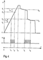
- the pump 113 should then be arranged so that it pumps as regularly and silently as possible. This measurement process will now be described using FIG. 4.
- the control circuit 25 then closes the valve 17 and starts the engine 114 running, so that the pump 113 inflates the chamber 3 of the cuff 1.
- the pressure p therefore increases regularly, at a speed which is advantageously at least approximately constant and which is for example from 2 to 5 kPa per second.
- the first Korotkoff noise signal is supplied to the control circuit 25 at time t 1 .
- the value P3 of the pressure measured at this instant t 1 is the upper limit value of the diastolic pressure range I D.
- the control circuit 25 finds that no Korotkoff noise has been emitted for a certain time, equal to three seconds for example, or that a predetermined maximum pressure has been reached.
- the pressure P2 measured in chamber 3 at time t 2 when the last Korotkoff noise was produced is therefore the pressure of the lower limit of the systolic pressure domain I S.
- control circuit could be arranged so that the chamber 3 is first inflated and then deflated quickly to determine the range of systolic pressure I S. Then the chamber 3 could be immediately re-inflated at least to the upper limit value of the systolic pressure range I S and then slowly deflated for the precise determination of the pressure deflated slowly for precise determination of systolic pressure. Then the diastolic pressure range I D could be determined during rapid deflation. The pressure should then be increased again to the upper limit value of the diastolic pressure range I D and a slow deflation should be carried out to determine the exact diastolic pressure.
- an electrically controlled pump should be provided to carry out the measurement in this way.
- the average speed of variation of the pressure p is significantly higher during the determination of the systolic pressure domains I S and diastolic pressure I D than during the determination of the systolic pressures p S and diastolic pressure D D they -same, regardless of whether the pressure varies in stages or continuously.
Landscapes
- Health & Medical Sciences (AREA)
- Life Sciences & Earth Sciences (AREA)
- Vascular Medicine (AREA)
- Cardiology (AREA)
- Biomedical Technology (AREA)
- Heart & Thoracic Surgery (AREA)
- Physiology (AREA)
- Biophysics (AREA)
- Pathology (AREA)
- Engineering & Computer Science (AREA)
- Ophthalmology & Optometry (AREA)
- Physics & Mathematics (AREA)
- Medical Informatics (AREA)
- Molecular Biology (AREA)
- Surgery (AREA)
- Animal Behavior & Ethology (AREA)
- General Health & Medical Sciences (AREA)
- Public Health (AREA)
- Veterinary Medicine (AREA)
- Measuring Pulse, Heart Rate, Blood Pressure Or Blood Flow (AREA)
Applications Claiming Priority (2)
| Application Number | Priority Date | Filing Date | Title |
|---|---|---|---|
| DE19813143871 DE3143871A1 (de) | 1981-11-05 | 1981-11-05 | "blutdruckmesseinrichtung und verfahren zur blutdruckmessung" |
| DE3143871 | 1981-11-05 |
Publications (3)
| Publication Number | Publication Date |
|---|---|
| EP0079305A2 true EP0079305A2 (de) | 1983-05-18 |
| EP0079305A3 EP0079305A3 (en) | 1984-11-14 |
| EP0079305B1 EP0079305B1 (de) | 1988-12-28 |
Family
ID=6145646
Family Applications (2)
| Application Number | Title | Priority Date | Filing Date |
|---|---|---|---|
| EP82810446A Expired EP0079305B1 (de) | 1981-11-05 | 1982-10-26 | Vorrichtung zur Messung des Blutdrucks |
| EP82810447A Withdrawn EP0079306A3 (de) | 1981-11-05 | 1982-10-26 | Verfahren zur Messung des Blutdrucks bei Personen |
Family Applications After (1)
| Application Number | Title | Priority Date | Filing Date |
|---|---|---|---|
| EP82810447A Withdrawn EP0079306A3 (de) | 1981-11-05 | 1982-10-26 | Verfahren zur Messung des Blutdrucks bei Personen |
Country Status (3)
| Country | Link |
|---|---|
| EP (2) | EP0079305B1 (de) |
| DE (2) | DE3143871A1 (de) |
| FR (1) | FR2515503A1 (de) |
Cited By (7)
| Publication number | Priority date | Publication date | Assignee | Title |
|---|---|---|---|---|
| DE3424535A1 (de) * | 1984-07-04 | 1986-01-09 | Bosch Gmbh Robert | Elektronisches blutdruckmessverfahren |
| EP0208520A2 (de) | 1985-07-05 | 1987-01-14 | Critikon, Inc. | Oszillometrische Blutdrucküberwachung während Druckablass mittels veränderlicher Druckintervalle |
| EP0197302A3 (de) * | 1985-03-11 | 1989-02-01 | TERUMO KABUSHIKI KAISHA trading as TERUMO CORPORATION | Verfahren und Apparat zur Messung der Kreislauffunktion |
| EP0353315A1 (de) * | 1988-08-01 | 1990-02-07 | Hewlett-Packard GmbH | Verfahren und Vorrichtung zur automatischen Blutdruckmessung |
| US5052397A (en) * | 1985-07-05 | 1991-10-01 | Critikon, Inc. | Oscillometric blood pressure monitor employing non-uniform pressure decrementing steps |
| EP0482242A1 (de) * | 1990-10-26 | 1992-04-29 | Hewlett-Packard GmbH | Verfahren und Vorrichtung zur automatischen Blutdrucküberwachung |
| EP0764425A1 (de) * | 1995-09-20 | 1997-03-26 | Colin Corporation | Blutdruckmessgerät |
Families Citing this family (5)
| Publication number | Priority date | Publication date | Assignee | Title |
|---|---|---|---|---|
| US4660567A (en) * | 1984-09-27 | 1987-04-28 | Takeda Medical Company Limited | Method of automatically measuring blood pressure, and apparatus therefor |
| US4754761A (en) * | 1985-07-05 | 1988-07-05 | Critikon, Inc. | Automated mean arterial blood pressure monitor with data enhancement |
| WO1991001682A1 (fr) * | 1989-07-28 | 1991-02-21 | Luc Teixeira De Carvalho | Procede et appareil ambulatoire pour mesurer en continu la tension arterielle |
| DE4010734A1 (de) * | 1990-04-03 | 1991-10-17 | Fraunhofer Ges Forschung | Einrichtung zur blutdruckmessung |
| JP3149669B2 (ja) * | 1994-02-28 | 2001-03-26 | オムロン株式会社 | 電子血圧計 |
Family Cites Families (17)
| Publication number | Priority date | Publication date | Assignee | Title |
|---|---|---|---|---|
| US2827040A (en) * | 1954-09-30 | 1958-03-18 | Saul R Gilford | Automatic sphygmomanometer |
| US3157177A (en) * | 1963-02-07 | 1964-11-17 | Dynamics Corp America | Systolic diastolic blood pressure follower |
| US3508537A (en) * | 1965-04-20 | 1970-04-28 | Beckman Instruments Inc | Method and apparatus for automatic blood pressure monitoring |
| US3814083A (en) * | 1972-05-24 | 1974-06-04 | Nasa | Apparatus and method for processing korotkov sounds |
| US4058117A (en) * | 1975-10-17 | 1977-11-15 | Palo Alto Research Associates | Blood pressure measuring apparatus |
| JPS52126981A (en) * | 1976-04-19 | 1977-10-25 | Nippon Roudou Bunka Kiyoukai | Device for measuring blood pressure |
| US4116230A (en) * | 1976-09-10 | 1978-09-26 | Gorelick Donald E | Blood pressure cuff automatic deflation device |
| US4216779A (en) * | 1977-05-16 | 1980-08-12 | Del Mar Avionics | Blood pressure monitoring system |
| HU176288B (en) * | 1977-12-21 | 1981-01-28 | Medicor Muevek | Apparatos to determine blood-pressure, in the first place, of babies not in a invasive way |
| US4349034A (en) * | 1978-04-10 | 1982-09-14 | Johnson & Johnson | Automatic mean blood pressure reading device |
| US4271844A (en) * | 1979-08-06 | 1981-06-09 | Medtek Corporation | Method and apparatus for performing non-invasive blood pressure and pulse rate measurements |
| CA1163327A (en) * | 1979-11-14 | 1984-03-06 | Ethicon, Inc. | Automated blood pressure measurement during physical exercise |
| US4312359A (en) * | 1980-02-19 | 1982-01-26 | Life Care Systems, Inc. | Noninvasive blood pressure measuring system |
| JPS596654B2 (ja) * | 1980-08-25 | 1984-02-14 | 松下電工株式会社 | 電子式血圧計 |
| FR2498440B1 (fr) * | 1981-01-29 | 1986-01-10 | Bard Inc C R | Procede et appareil pour mesurer la pression |
| DE3109822A1 (de) * | 1981-03-14 | 1982-09-30 | Honeywell B.V., Amsterdam | Blutdruckmessgeraet |
| US4408614A (en) * | 1981-07-06 | 1983-10-11 | Sri International | Blood pressure measurement with Korotkov sound artifact information detection and rejection |
-
1981
- 1981-11-05 DE DE19813143871 patent/DE3143871A1/de not_active Withdrawn
-
1982
- 1982-03-04 FR FR8203804A patent/FR2515503A1/fr active Pending
- 1982-10-26 EP EP82810446A patent/EP0079305B1/de not_active Expired
- 1982-10-26 EP EP82810447A patent/EP0079306A3/de not_active Withdrawn
- 1982-10-26 DE DE8282810446T patent/DE3279301D1/de not_active Expired
Cited By (12)
| Publication number | Priority date | Publication date | Assignee | Title |
|---|---|---|---|---|
| DE3424535A1 (de) * | 1984-07-04 | 1986-01-09 | Bosch Gmbh Robert | Elektronisches blutdruckmessverfahren |
| EP0197302A3 (de) * | 1985-03-11 | 1989-02-01 | TERUMO KABUSHIKI KAISHA trading as TERUMO CORPORATION | Verfahren und Apparat zur Messung der Kreislauffunktion |
| EP0208520A2 (de) | 1985-07-05 | 1987-01-14 | Critikon, Inc. | Oszillometrische Blutdrucküberwachung während Druckablass mittels veränderlicher Druckintervalle |
| JPS628735A (ja) * | 1985-07-05 | 1987-01-16 | クリテイコン・インコ−ポレイテツド | 不等圧力減少ステップを用いたオシロメトリック法血圧計 |
| EP0208520A3 (en) * | 1985-07-05 | 1988-07-13 | Critikon, Inc. | Oscillometric blood pressure monitor employing non uniform pressure decrementing steps |
| US5052397A (en) * | 1985-07-05 | 1991-10-01 | Critikon, Inc. | Oscillometric blood pressure monitor employing non-uniform pressure decrementing steps |
| EP0353315A1 (de) * | 1988-08-01 | 1990-02-07 | Hewlett-Packard GmbH | Verfahren und Vorrichtung zur automatischen Blutdruckmessung |
| EP0482242A1 (de) * | 1990-10-26 | 1992-04-29 | Hewlett-Packard GmbH | Verfahren und Vorrichtung zur automatischen Blutdrucküberwachung |
| US5215096A (en) * | 1990-10-26 | 1993-06-01 | Hewlett Packard Company | Method and apparatus for automatic blood pressure monitoring |
| EP0764425A1 (de) * | 1995-09-20 | 1997-03-26 | Colin Corporation | Blutdruckmessgerät |
| US5730139A (en) * | 1995-09-20 | 1998-03-24 | Colin Corporation | Blood pressure measuring apparatus |
| US6068601A (en) * | 1995-09-20 | 2000-05-30 | Colin Corporation | Blood pressure measuring apparatus |
Also Published As
| Publication number | Publication date |
|---|---|
| FR2515503A1 (fr) | 1983-05-06 |
| EP0079306A2 (de) | 1983-05-18 |
| EP0079306A3 (de) | 1984-11-07 |
| DE3279301D1 (en) | 1989-02-02 |
| EP0079305B1 (de) | 1988-12-28 |
| EP0079305A3 (en) | 1984-11-14 |
| DE3143871A1 (de) | 1983-05-19 |
Similar Documents
| Publication | Publication Date | Title |
|---|---|---|
| FR2677535A1 (fr) | Systeme de controle de la pression arterielle. | |
| EP0079305B1 (de) | Vorrichtung zur Messung des Blutdrucks | |
| FR2475880A1 (fr) | Dispositif de mesure de la pression sanguine | |
| EP0064475B1 (de) | Verfahren zur Messung des Blutdrucks und Sphygmomanometer zur Anwendung des Verfahrens | |
| EP0493222B1 (de) | Verfahren zur Steuerung eines Herzschrittmachers mit einer gesteuerten Reizungsfrequenz | |
| FR2475883A1 (fr) | Dispositif de mesure de la pression sanguine | |
| TWI471118B (zh) | 具有纏繞於測定部位之套圈的血壓測定裝置 | |
| FR2678157A1 (fr) | Systeme de controle de la pression sanguine. | |
| BE1004497A5 (fr) | Instrument de mesure de niveau de stress. | |
| JP6019592B2 (ja) | 血圧測定装置 | |
| CN113520307A (zh) | 血压的测量方法、装置及可穿戴设备 | |
| FR2673368A1 (fr) | Systeme de mesure automatique de la pression sanguine. | |
| FR2466975A1 (fr) | Systeme automatique de mesure de la pression arterielle | |
| JPH04279147A (ja) | 自動血圧計 | |
| CH624567A5 (de) | ||
| FR2475881A1 (fr) | Dispositif de mesure de la pression sanguine a microphone ou capteur de son equivalent | |
| JPH0751123B2 (ja) | 指用電子血圧計 | |
| US12593992B2 (en) | Sphygmomanometer, personal authentication method on a sphygmomanometer, and computer-readable recording medium | |
| EP0221981A1 (de) | Vorrichtung zum automatischen messen des blutdrucks | |
| FR2530137A1 (fr) | Tensiometre electronique | |
| EP1580525A1 (de) | Verfahren zur Detektion des Beginns eines Tauchgangs für Tauchcomputer | |
| JPS63311933A (ja) | 電子血圧計 | |
| WO1995007650A1 (fr) | Procede et dispositif pour l'etude, le diagnostic et le traitement du systeme cardiovasculaire, notamment arteriel | |
| JPH084575B2 (ja) | 電子血圧計 | |
| FR2696645A1 (fr) | Insufflateur pour le traitement d'une cavité du corps d'un patient. |
Legal Events
| Date | Code | Title | Description |
|---|---|---|---|
| PUAI | Public reference made under article 153(3) epc to a published international application that has entered the european phase |
Free format text: ORIGINAL CODE: 0009012 |
|
| AK | Designated contracting states |
Designated state(s): CH DE FR GB LI |
|
| PUAL | Search report despatched |
Free format text: ORIGINAL CODE: 0009013 |
|
| AK | Designated contracting states |
Designated state(s): CH DE FR GB LI |
|
| 17P | Request for examination filed |
Effective date: 19850504 |
|
| 17Q | First examination report despatched |
Effective date: 19860708 |
|
| GRAA | (expected) grant |
Free format text: ORIGINAL CODE: 0009210 |
|
| AK | Designated contracting states |
Kind code of ref document: B1 Designated state(s): CH DE FR GB LI |
|
| REF | Corresponds to: |
Ref document number: 3279301 Country of ref document: DE Date of ref document: 19890202 |
|
| GBT | Gb: translation of ep patent filed (gb section 77(6)(a)/1977) | ||
| PLBE | No opposition filed within time limit |
Free format text: ORIGINAL CODE: 0009261 |
|
| STAA | Information on the status of an ep patent application or granted ep patent |
Free format text: STATUS: NO OPPOSITION FILED WITHIN TIME LIMIT |
|
| 26N | No opposition filed | ||
| PGFP | Annual fee paid to national office [announced via postgrant information from national office to epo] |
Ref country code: GB Payment date: 19900917 Year of fee payment: 9 |
|
| PGFP | Annual fee paid to national office [announced via postgrant information from national office to epo] |
Ref country code: FR Payment date: 19901015 Year of fee payment: 9 |
|
| PGFP | Annual fee paid to national office [announced via postgrant information from national office to epo] |
Ref country code: DE Payment date: 19901019 Year of fee payment: 9 Ref country code: CH Payment date: 19901019 Year of fee payment: 9 |
|
| PG25 | Lapsed in a contracting state [announced via postgrant information from national office to epo] |
Ref country code: GB Effective date: 19911026 |
|
| PG25 | Lapsed in a contracting state [announced via postgrant information from national office to epo] |
Ref country code: LI Effective date: 19911031 Ref country code: CH Effective date: 19911031 |
|
| GBPC | Gb: european patent ceased through non-payment of renewal fee | ||
| PG25 | Lapsed in a contracting state [announced via postgrant information from national office to epo] |
Ref country code: FR Effective date: 19920630 |
|
| REG | Reference to a national code |
Ref country code: CH Ref legal event code: PL |
|
| PG25 | Lapsed in a contracting state [announced via postgrant information from national office to epo] |
Ref country code: DE Effective date: 19920701 |
|
| REG | Reference to a national code |
Ref country code: FR Ref legal event code: ST |