EP0079370B1 - Ordinateur numerique pouvant executer des instructions en trois parties multiplexees dans le temps - Google Patents
Ordinateur numerique pouvant executer des instructions en trois parties multiplexees dans le temps Download PDFInfo
- Publication number
- EP0079370B1 EP0079370B1 EP82901669A EP82901669A EP0079370B1 EP 0079370 B1 EP0079370 B1 EP 0079370B1 EP 82901669 A EP82901669 A EP 82901669A EP 82901669 A EP82901669 A EP 82901669A EP 0079370 B1 EP0079370 B1 EP 0079370B1
- Authority
- EP
- European Patent Office
- Prior art keywords
- instruction
- microcommands
- memory
- microcode
- instructions
- Prior art date
- Legal status (The legal status is an assumption and is not a legal conclusion. Google has not performed a legal analysis and makes no representation as to the accuracy of the status listed.)
- Expired
Links
Images


Classifications
-
- G—PHYSICS
- G06—COMPUTING OR CALCULATING; COUNTING
- G06F—ELECTRIC DIGITAL DATA PROCESSING
- G06F9/00—Arrangements for program control, e.g. control units
- G06F9/06—Arrangements for program control, e.g. control units using stored programs, i.e. using an internal store of processing equipment to receive or retain programs
- G06F9/22—Microcontrol or microprogram arrangements
- G06F9/28—Enhancement of operational speed, e.g. by using several microcontrol devices operating in parallel
Definitions
- This invention relates to the architecture of digital computers, and more particularly it relates to the control circuitry in a digital computer which directs the sequence by which instructions are executed within the computer.
- the instructions which a digital computer executes are stored in a memory. Also, those instructions in the memory are arranged in a particular sequence called a program. And the computer must execute those instructions in that sequence in order to obtain the correct results.
- a common sequence by which a digital computer operates is to fetch one instruction from the memory, then execute that instruction, then fetch the next instruction from memory, then execute that instruction, etc.
- This sequence is used, for example, in the IBM System/360, Model 50. See Microprogramming, Principles and Practices, 1970, page 34 by Samir S. Husson.
- the instructions generally call for operands to be fetched from and stored into the memory.
- the above instruction execution sequence is performed as follows. First, the digital computer fetches one instruction from the memory. Next the computer iterprets that instruction. Next the computer fetches any operands that are required from the memory. Next, the computer performs arithmetic operations on those operands. And, next the computer stores the results back in the memory. This sequence is then repeated for the next instruction.
- the time that it takes to read an instruction or an operand from the memory is generally larger than the time that it takes the digital computer to perform an internal arithmetic operation on two operands.
- the memory read time may be one microsecond; whereas the digital computer internal cycle time may be only 0.1 microseconds.
- the digital computer spends most of its time doing nothing because it must wait for the memory to supply its requested instructions and operands.
- Another solution is to construct the digital computer's control circuitry such that the computer executes several different programs in a time-multiplexed fashion. See for example, U.S. Patent 3,980,992 to Levy et al.
- the computer can execute the first program until a memory read is made. At that point, the computer must stop executing the first program and start executing the second program. Execution of the second program can continue until a memory read for that program is made. Then the computer must start executing the third program. This sequence can continue until a memory read is made in the last program; in which case, the computer switches back to the first program and continues executing it from the point where it previously stopped.
- the digital computer has useful work to perform between its initiation of a read from the memory and the receipt of the requested information.
- efficient use is made of the computer's time, even though the memory is relatively slow.
- Another solution to the above problem is to construct the digital computer's control circuitry so that various portions of more than one instruction in a single program are processed in a time-interleaved sequence.
- the computer may initiate the read for the next instruction that it is to perform prior to interpreting and executing the present invention.
- that next instruction will be available from the memory when the time comes to perform it.
- This sequence is used, for example, in the IBM 7094. See Introduction to Computer Architecture, 1975, pages 383-384.
- the invention relates to a digital computer for executing instructions of a single program in a time-multiplexed fashion, said digital computer including a control memory.
- said computer is characterised in that in said control memory each of said instructions is represented by first, second, and third sets of microcommands where said first set of microcommands must be executed before said second set, and said second set must be executed before said third set; and a control means for executing in a time-multiplexed iterative sequence, said third set of microcommands for a first instruction in said program, followed directly by said second set of microcommands for a second instruction in said program after said first instruction, followed directly by said first set of microcommands for a third instruction in said program after said second instruction, none of said sets of microcommands being executed simultaneously.
- computer 10 is comprised of an arithmetic section 20, an input/output section 30, and a control section 40.
- Arithmetic section 20 operates to perform functions on operands as specified by instructions;
- input/output section 30 operates to fetch those instructions and operands;
- control section 40 operates to sequence the execution of those instructions by directing the operation of arithmetic section 20 and input/output section 30.
- Those instructions that are to be performed are stored in a memory 50 which couples to input/ output section 30 via a bus 60.
- the instructions are represented by the symbols 1 1 , 1 2 , 1 3 .... From a programmer's point of view, instructions 1 1 , 1 2 , 1 3 ... form an instruction string in a program wherein the first instruction 1 1 is completely executed, then the next instruction 1 2 is completely executed, then the next instruction 1 3 is completely executed, etc.
- control section 40 divides each of those instructions into three parts and executes those parts for several different instructions in a time-interleaved sequence. To the programmer it appears that instructions 1 1 , 1 2 , ... are still being executed one-at-a-time. But due to the interleaving, the time it takes to execute the instruction strings in the program is substantially reduced.
- section 20 includes a register file 21, a multiplexer 22, and arithmetic unit 23. These components are interconnected in a serial fashion such that in one cycle of computer 10, operands in register file 21 are selectively passed through multiplexer 22 to arithmetic unit 23; and the result from arithmetic unit 23 is sent via a bus 24 back to one of the registers in file 21.
- Register IAR is an instruction address register which addresses one of the instructions 11,12, 1 3 ... in memory 50.
- Register TOS is a top of stack register which holds one operand. All of the remainder of the stack is contained in memory 50. There, symbol TOS-1 indicates the top of stack minus one; symbol TOS-2 indicates the top of stack minus two; etc.
- Register SOV is a stack overflow register which is incremented or decremented each time the stack is popped or pushed to keep track of the number of vacancies in the stack.
- registers R1,..., RN are general purpose registers which are utilized to store various items such as addresses for memory 50 or intermediate results of arithmetic operations.
- Section 30 of computer 10 includes an output queue 31 and an input queue 32.
- Output queue 31 operates to receive messages from the arithmetic section 20 for transmission to memory 50; and it operates to buffer those messages until they are actually sent over the bus 60.
- Those messages for example, include a request for an instruction from memory. 50, a request for data from the stack portion in memory 50, or the transmission of data for storage in the stack portion in memory 50.
- Input queue 32 operates to receive messages from memory 50 over bus 60; and it holds those messages until they are needed by arithmetic unit 20. Those messages from bus 60 include instructions which were previously requested by the output queue.
- time interval ⁇ T1 must occur between the sending of a request for data from output queue 31 and the receipt of that data in input queue 32. And that time interval must necessarily be several times larger than the time interval ⁇ T2 that it takes to pass data from register file 21 through multiplexer 22 and arithmetic unit 23 back to the register file.
- time interval AT1 is five to ten times larger than time interval AT2. The exact multiple depends upon the speed of memory 50 and the contention for bus 60 from other devices (not shown). Thus, it is highly desirable for computer 10 to have some useful tasks to perform between the requesting of data via output queue 31 and the receipt of that data on input queue 32. Otherwise, computer 10 will have to wait and do nothing until the data arrives.
- control section 40 includes a control memory 41 in which each of the instructions 1 1 , 1 2 , 1 3 , ... is represented by three sets of microcode S A , S B , and S c .
- Those microcode sets which implement instruction 1 1 are indicated in control memory 41 as S A 1 , S B 1 , and Sc 1 ;
- those microcode sets which implement instruction 1 2 are indicated as S A 2 , S a 2 , and S c 2 ; etc.
- microcode in set S A must be peformed before microcode in set S B , and microcode in set S B must be performed before the microcode in set S c . But this does not mean that the microcode in sets S A , S B , and S c for each particular instruction must be performed immediately after one another. And in the present invention, the execution of the microcode in sets S A , S B , and S c for each particular instruction is interleaved with the excecution of microcode sets for other instructions.
- Another constraint on the microcode sets S A , S B , and S c is that set S A microcode performs pops from that portion of the stack that resides in memory 50, set S B microcode performs pops on that portion of the stack that resides in arithmetic unit 20 and performs pushes on that portion of the stack that resides in memory 50; and set S c microcode performs pushes on that portion of the stack that resides in arithmetic unit 20.
- Control memory 41 also includes one common set of microcode COM; and it operates to send requests for instructions via output queue 31 and to receive those requested instructions on input queue 32.
- This common set of microcode is executed along with the above-described microcode sets S A , S a , and S c in a time-multiplexed iterative sequence which is herein represented symbolically as COM, S C I-3 , S B I-2 , S A I-1 .
- control section 40 includes a control memory addressing circuit 43.
- circuit 43 first forms control memory addresses CMA for the common microcode sets; then it forms addresses for microcode set S c of instruction 1 1 - 3 ; then it forms addresses for microcode set S B of instruction l i-2 ; and then it forms addresses of microcode set S A of instruction I I ⁇ 1 . That sequence is then repeated over and over with the variable i being updated by one each time.
- Each address formed by circuit 43 is sent over bus 44 to select a corresponding microcommand from control memory 41; and that command is loaded into a control memory register 45. From there, various portions of the microcommand are coupled via leads 46 to control the operation of arithmetic unit 20, input/output unit 30, and control memory addressing circuit 43.
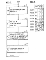
- FIG. 71 indicates that computer 10 begins its iterative time-multiplexed operation by executing the common set of microcode COM. That microcode sends a fetch via output queue 31 for instruction I in memory 50; and it takes instruction l I ⁇ 1 from input queue 32. Note that instruction 1 1 - 1 was fetched in a previous pass through the iterative sequence.
- computer 10 executes microcode in set S c of instruction l I ⁇ 3 . That microcode takes the last word that is to be operated on from input queue 32, performs any arithmetic operations that are required on that last word and any register in file 21, and pushes the result onto the top of stack register TOS.
- the data that is being taken from input queue 32 was fetched in a previous pass through the iterative sequence.
- microcode in set S B for instruction 1 1 - 2 is executed. That microcode takes from input queue 32 all words from the stack in main memory 50 that are to be operated on except the last word. Also, it performs arithmetic operations on those words and performs all pushes via output queue 31 to the stack in memory 50. Again, the data that is here taken from input queue 32 has been fetched in a previous pass through the iterative cycle.
- microcode in set S A for instruction 1 1 - 1 is executed. That microcode sends pop commands via output queue 31 to the stack in memory 50. That is, operands which are required by instruction 1 1 - 1 from the stack portion in memory 50 are fetched by this set of microcode. Thereafter, the indexing variable i is updated by one; and the iterative sequence is repeated.
- computer 10 always has some useful work to perform between the fetching of an instruction from memory 50 via output queue 31 and the receipt of that instruction on the input queue.
- computer 10 fetches instruction l I in block 71 and then it performs all of the tasks indicated in blocks 72, 73, and 74 before it is ready to receive the fetched instruction.
- computer 10 is not simply waiting for the fetched instruction to come back from memory 50.
- Still another important feature of the above operation of computer 10 is that all pushes to the stack in memory 50 by any one instruction occur after all arithmetic operations are complete by the preceding instruction. This is evident by inspection of blocks 72 and 73 wherein in box 72 arithmetic operations are completed for instruction 1 1 - 3 and in block 73 pushes to the stack in memory 50 begin for instruction I I _ 2 . If some of the pushes to the stack in memory 50 for instruction 1 1 - 2 began before all of the arithmetic operations for instruction 1 1 - 3 were complete, then some of the data being pushed onto the stack would be stale, which again would cause errors.
- Figure 3 includes a matrix having columns labelled COM, S c , S B , and S A ; having rows labelled CYCLE 1 through CYCLE 8; and having numbers in the various row-column locations which indicate the instruction that is being executed.
- Computer 10 executes the labelled microcode sets for one cycle in a left to right sequence; then it executes the labelled microcode sets for the next cycle in a left to right sequence; etc.
- computer 10 first executes the common set of microcode COM which fetches instruction 4 via output queue 31 and receives instruction 3 in input queue 32.
- computer 10 executes microcode set S c for instruction 1; then it executes microcode set S B for instruction 2; and then it executes microcode set S A for instruction 3.
- the common microcode set is executed wherein a fetch for instruction 5 is sent and instruction 4 is received.
- microcode set S c for instruction 2 is executed; then microcode set S B for instruction 3 is executed; then microcode set S A for instruction 4 is executed, etc.
- cycles 1-3 indicate the operation of computer 10 when it is first powered on. There, some of the microcode sets must be skipped, as indicated by the Xs in the matrix, because there are no prior instructions to operate on. But this skipping only occurs once (at POWER ON); and so its effect on the computer's performance is insignificant.
- Figure 3 also shows the operation of computer 10 when one of the instructions 1 1 , 1 2 , 1 3 ... is branch conditional instruction. If the branch is not taken, then computer 10 merely sequences as was described above in conjunction with cycles 4 and 5. But if the branch is taken, then computer 10 operates in a slightly different fashion as indicated by cycles 6, 7, and 8. There it is assumed that the fifth instruction is the branch conditional instruction and that the condition to be tested is such that the branch is taken.
- a branch instruction can test a condition that is set up by the previous instruction, which in this case is instruction 4. But instruction 4 does not complete its execution until cycle 7; and thus microcode set S B for the branch instruction can test that condition. If the branch is to be taken, then microcode set S B for the branch instruction fetches both the instruction to be branched to and the following instruction. In Figure 3, those two instructions are assumed to be instruction 1 and 2.
- microcode set S B for the branch removes any other pre-fetched instructions from the input queue (which in Figure 3 are instructions 7 and 6). Then it takes the instruction that is being branched to from the input queue and branches to microcode set S A for that instruction. Thereafter, the sequence continues as was described above.
- Microcode sets S A and S c for the branch instruction merely are one microcommand which branches to the next microcode set in the sequence.
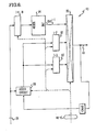
- That addressing circuit includes registers 81, 82, and 83 which are interconnected to each other in a serial fashion.
- Register 81 receives its inputs from arithmetic section 20 on bus 24;
- register 82 receives its inputs from register 81;
- register 83 receives its inputs from register 82.
- instruction 1 1 - 1 is transferred from input queue 32 to register 81 by the common microcode COM.
- the previous contents of register 81 are transferred to register 82 and the previous contents of register 82 are transferred to register 83. That operation is performed each time the common microcode is executed.
- Three memories 84,85, and 86 are also included in the addressing circuit 43. Memories 84,85, and 86 are addressed respectively by registers 81, 82, and 83. Outputs from those memories are sent to a multiplexer 87 whose output forms the address CMA for control memory 41 on bus 44.
- Memory 84 stores the beginning addresses for the microcode sets S A for all of the instructions. And since memory 84 is addressed by instruction 1 1 - 1 , the output of memory 84 is the beginning address for microcode set S A of instruction I i ⁇ 1 . Similarly, memory 85 stores the beginning addresses for microcode set S B of all of the instructions; and memory 86 stores the beginning address for microcode set S c for all of the instructions. And since memories 85 and 86 are respectively addressed by instructions 1 1 - 2 and I i ⁇ 3 , their respective outputs are the beginning addresses for microcode set S B of instruction 1 1 - 2 and the beginning address of microcode set S c for instruction I i ⁇ 3 .
- control signals on leads 46 from the control memory register are sent to multiplexer 87 to select the outputs from one of the memories 84, 85, and 86. Then, after the microcode set has been entered, that control memory address is incremented or decremented by an adder circuit 88 in response to control signals on leads 46. Test conditions on bus 24 are also sent to adder circuit 88 to permit testing and branching within each of the microcode sets.
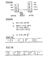
- Figure 5A illustrates the microcode sets for a "logical OR instruction".
- the stack is as indicated in the left-hand portion of Figure 5A wherein N1, N2, and N3 are the top three entries in the stack.
- the top of stack entry is the result R that is obtained by logically ORing N1 and N2; and the next entry in the stack is N3.
- S A a request is sent via output queue 31 for the top of stack minus one operand in memory 50 to be read; and a jump is taken to the common set of microcode. That jump is in accordance with the previously described iterative sequences of Figures 1-4.
- Microcode set S B adds one to the stack overflow register; and it jumps to microcode set S A for instruction I i ⁇ 1 . This jump is achieved by selecting the output of memory 84 as the control memory address on leads 44; and it too is in accordance with the previously described sequences of Figures 1-4.
- Microcode set S c ORs the input queue with the top of stack register; stores the result in the top of stack register; and jumps to microcode set S B for instruction I i ⁇ 2 . That jump is achieved by selecting the output of memory 85 as the control memory address on leads 44. Note that the output of memory 86 is not called for in these sets S A , S B , or S c because that occurs at the end of the common microcode routine.
- Figures 6A and 6B illustrate microcode sets S A , S a , and S c for the "fetch simple variable" instruction. That instruction operates to fetch a variable from memory 50 and to put it on the top of stack. This operation is indicated in Figure 6A.
- microcode set S A sends a command to memory 50 via output queue 31 which says read the variable V; and it jumps to the common microcode routine.
- Microcode set S a sends a command to memory 50 via output queue 31 which says write into the top of stack minus one location. Then the top of stack register is loaded into the output queue so that it can be transferred to memory 50.
- microcode set S A of instruction I i ⁇ 1 the stack overflow register is updated, and a jump is taken to microcode set S A of instruction I i ⁇ 1 .
- microcode set S c the variable V that was requested by the microcode set S A is taken from input queue 32 and loaded into the top of stack register. Then a jump is taken to microcode set S B of instruction I i ⁇ 2 .
- each instruction is divided into only two microcode sets, S x and Sy.
- microcode set S x for instruction I is executed first; then microcode set Sy for instruction I i ⁇ 1 is executed; and then the sequence repeats.
- microcode set S x for instruction I i is executed; then microcode set Sy for instruction 1 1 - 2 is executed; and then the sequence repeats.
- the push in instruction 1, of TOS must follow S Y i ⁇ 1 , wherein TOS is modified. Otherwise, stale data will be pushed onto the stack, as was also described previously in conjunction with Figure 2. Therefore, the push in instruction I, must both follow S Y i ⁇ 1 and precede S X 1+1 .
- This memory addressing circuit includes three registers 91, 92, and 93.
- Register 91 receives its inputs from bus 24; and its outputs address a memory 94. That memory has its outputs coupled to a multiplexer 95; and the output of multiplexer 95 forms the control memory address CMA on bus 44.
- Memory 94 stores the beginning addresses of all of the microcode sets S A for all of the instructions.
- the common routine loads instruction I i ⁇ 1 into register 91; and thus the output of memory 94 is the beginning address of microcode set S A for instruction I i ⁇ 1 . That address is selectively passed through multiplexer 94 in response to control signals on bus 46 from the last microcommand in set S e .
- microcode set S A is entered, an adder circuit 96 is utilized to increment and conditionally modify the control memory address CMA as was previously described in conjunction with the Figure 4 circuit. Then, when execution of the microcode in set S A is complete, a jump is taken to the common microcode set; and in addition, register 92 is loaded with the beginning address of microcode set S B for the instruction whose S A microcode is being exited. That beginning address in this embodiment is formed by adder circuit 96.
- microcode sets S A and S B respectively form the beginning addresses for sets S B and S c , which eliminates the need for three memories 84, 85, and 86 as in the Figure 4 embodiment.
Landscapes
- Engineering & Computer Science (AREA)
- Software Systems (AREA)
- Theoretical Computer Science (AREA)
- Physics & Mathematics (AREA)
- General Engineering & Computer Science (AREA)
- General Physics & Mathematics (AREA)
- Executing Machine-Instructions (AREA)
- Advance Control (AREA)
Claims (8)
Applications Claiming Priority (2)
| Application Number | Priority Date | Filing Date | Title |
|---|---|---|---|
| US06/266,599 US4430708A (en) | 1981-05-22 | 1981-05-22 | Digital computer for executing instructions in three time-multiplexed portions |
| US266599 | 1981-05-22 |
Publications (3)
| Publication Number | Publication Date |
|---|---|
| EP0079370A1 EP0079370A1 (fr) | 1983-05-25 |
| EP0079370A4 EP0079370A4 (fr) | 1986-06-05 |
| EP0079370B1 true EP0079370B1 (fr) | 1989-06-07 |
Family
ID=23015244
Family Applications (1)
| Application Number | Title | Priority Date | Filing Date |
|---|---|---|---|
| EP82901669A Expired EP0079370B1 (fr) | 1981-05-22 | 1982-04-15 | Ordinateur numerique pouvant executer des instructions en trois parties multiplexees dans le temps |
Country Status (5)
| Country | Link |
|---|---|
| US (1) | US4430708A (fr) |
| EP (1) | EP0079370B1 (fr) |
| JP (1) | JPS58500778A (fr) |
| DE (1) | DE3279759D1 (fr) |
| WO (1) | WO1982004148A1 (fr) |
Families Citing this family (10)
| Publication number | Priority date | Publication date | Assignee | Title |
|---|---|---|---|---|
| US4463423A (en) * | 1982-07-14 | 1984-07-31 | Burroughs Corporation | Method of transforming high level language statements into multiple lower level language instruction sets |
| US4484272A (en) * | 1982-07-14 | 1984-11-20 | Burroughs Corporation | Digital computer for executing multiple instruction sets in a simultaneous-interleaved fashion |
| US5179734A (en) * | 1984-03-02 | 1993-01-12 | Texas Instruments Incorporated | Threaded interpretive data processor |
| US4742451A (en) * | 1984-05-21 | 1988-05-03 | Digital Equipment Corporation | Instruction prefetch system for conditional branch instruction for central processor unit |
| US5062036A (en) * | 1985-06-10 | 1991-10-29 | Wang Laboratories, Inc. | Instruction prefetcher |
| US5142681A (en) * | 1986-07-07 | 1992-08-25 | International Business Machines Corporation | APL-to-Fortran translators |
| US5185870A (en) * | 1987-04-10 | 1993-02-09 | Tandem Computers, Inc, | System to determine if modification of first macroinstruction to execute in fewer clock cycles |
| US5005118A (en) * | 1987-04-10 | 1991-04-02 | Tandem Computers Incorporated | Method and apparatus for modifying micro-instructions using a macro-instruction pipeline |
| ES2148492T3 (es) * | 1994-01-10 | 2000-10-16 | Dow Chemical Co | Ordenador de arquitectura harvard superescalar masivamente multiplexado. |
| US5555424A (en) * | 1994-10-06 | 1996-09-10 | The Dow Chemical Company | Extended Harvard architecture computer memory system with programmable variable address increment |
Family Cites Families (5)
| Publication number | Priority date | Publication date | Assignee | Title |
|---|---|---|---|---|
| JPS514381B1 (fr) | 1969-11-24 | 1976-02-10 | ||
| GB1257760A (fr) * | 1970-10-10 | 1971-12-22 | ||
| US4103326A (en) | 1977-02-28 | 1978-07-25 | Xerox Corporation | Time-slicing method and apparatus for disk drive |
| US4197579A (en) | 1978-06-06 | 1980-04-08 | Xebec Systems Incorporated | Multi-processor for simultaneously executing a plurality of programs in a time-interlaced manner |
| US4229790A (en) | 1978-10-16 | 1980-10-21 | Denelcor, Inc. | Concurrent task and instruction processor and method |
-
1981
- 1981-05-22 US US06/266,599 patent/US4430708A/en not_active Expired - Lifetime
-
1982
- 1982-04-15 WO PCT/US1982/000469 patent/WO1982004148A1/fr not_active Ceased
- 1982-04-15 EP EP82901669A patent/EP0079370B1/fr not_active Expired
- 1982-04-15 JP JP57501621A patent/JPS58500778A/ja active Granted
- 1982-04-15 DE DE8282901669T patent/DE3279759D1/de not_active Expired
Non-Patent Citations (3)
| Title |
|---|
| IEEE Computer, October 1980, pp. 5-16, 18-22 * |
| IEEE TRANSACTIONS ON COMPUTERS, vol. C-27, no. 3, March 1978, pp. 270-275, IEEE, New York, US, L.G. HIGBIE: "Overlapped operation with microprogramming" * |
| Rechnerstrukturen, Vorträge des Informatik-Symposiums der IBM-Deutschland, Wildbad 1973, Ed. by H. Hasselmeier and W.G. Spruth, R. Oldenbourg-Verlag München, Wien 1974, pp. 104-150 * |
Also Published As
| Publication number | Publication date |
|---|---|
| JPS58500778A (ja) | 1983-05-12 |
| DE3279759D1 (en) | 1989-07-13 |
| JPS6112290B2 (fr) | 1986-04-07 |
| WO1982004148A1 (fr) | 1982-11-25 |
| US4430708A (en) | 1984-02-07 |
| EP0079370A1 (fr) | 1983-05-25 |
| EP0079370A4 (fr) | 1986-06-05 |
Similar Documents
| Publication | Publication Date | Title |
|---|---|---|
| US4734852A (en) | Mechanism for performing data references to storage in parallel with instruction execution on a reduced instruction-set processor | |
| US4875160A (en) | Method for implementing synchronous pipeline exception recovery | |
| US5261113A (en) | Apparatus and method for single operand register array for vector and scalar data processing operations | |
| US4399507A (en) | Instruction address stack in the data memory of an instruction-pipelined processor | |
| EP0365188B1 (fr) | Méthode et dispositif pour code de condition dans un processeur central | |
| US6338136B1 (en) | Pairing of load-ALU-store with conditional branch | |
| US6081887A (en) | System for passing an index value with each prediction in forward direction to enable truth predictor to associate truth value with particular branch instruction | |
| US4587632A (en) | Lookahead stack oriented computer | |
| EP0476722B1 (fr) | Système de traitement de données | |
| JPH0374434B2 (fr) | ||
| US4967338A (en) | Loosely coupled pipeline processor | |
| JPS5831014B2 (ja) | 命令先取り装置 | |
| EP0352082B1 (fr) | Adressage des microinstructions dans une unité centrale de type pipe-line ( méthode d'operation, méthode d'adressage, mémoire de pile, unité centrale ) | |
| KR100875377B1 (ko) | 처리 시스템에서 스택 팝 및 푸쉬 동작들을 수행하는 장치 및 방법 | |
| US5765007A (en) | Microinstruction sequencer having multiple control stores for loading different rank registers in parallel | |
| US4430708A (en) | Digital computer for executing instructions in three time-multiplexed portions | |
| KR100210205B1 (ko) | 스톨캐쉬를 제공하기 위한 장치 및 방법 | |
| JP2742374B2 (ja) | スーパースカラ・プロセッサ・システムにおける命令ディスパッチ効率を向上させる方法およびシステム | |
| JPS5918738B2 (ja) | 割込みシステム | |
| US5434986A (en) | Interdependency control of pipelined instruction processor using comparing result of two index registers of skip instruction and next sequential instruction | |
| US6161171A (en) | Apparatus for pipelining sequential instructions in synchronism with an operation clock | |
| US5590293A (en) | Dynamic microbranching with programmable hold on condition, to programmable dynamic microbranching delay minimization | |
| US5586337A (en) | Programmable controller with timing control | |
| US7134000B2 (en) | Methods and apparatus for instruction alignment including current instruction pointer logic responsive to instruction length information | |
| US5363490A (en) | Apparatus for and method of conditionally aborting an instruction within a pipelined architecture |
Legal Events
| Date | Code | Title | Description |
|---|---|---|---|
| PUAI | Public reference made under article 153(3) epc to a published international application that has entered the european phase |
Free format text: ORIGINAL CODE: 0009012 |
|
| 17P | Request for examination filed |
Effective date: 19820705 |
|
| AK | Designated contracting states |
Designated state(s): BE DE FR GB NL |
|
| A4 | Supplementary search report drawn up and despatched |
Effective date: 19860605 |
|
| RAP1 | Party data changed (applicant data changed or rights of an application transferred) |
Owner name: BURROUGHS CORPORATION (A DELAWARE CORPORATION) |
|
| RAP1 | Party data changed (applicant data changed or rights of an application transferred) |
Owner name: UNISYS CORPORATION |
|
| 17Q | First examination report despatched |
Effective date: 19870918 |
|
| GRAA | (expected) grant |
Free format text: ORIGINAL CODE: 0009210 |
|
| AK | Designated contracting states |
Kind code of ref document: B1 Designated state(s): BE DE FR GB NL |
|
| REF | Corresponds to: |
Ref document number: 3279759 Country of ref document: DE Date of ref document: 19890713 |
|
| ET | Fr: translation filed | ||
| PLBE | No opposition filed within time limit |
Free format text: ORIGINAL CODE: 0009261 |
|
| STAA | Information on the status of an ep patent application or granted ep patent |
Free format text: STATUS: NO OPPOSITION FILED WITHIN TIME LIMIT |
|
| 26N | No opposition filed | ||
| PG25 | Lapsed in a contracting state [announced via postgrant information from national office to epo] |
Ref country code: FR Effective date: 19901228 |
|
| REG | Reference to a national code |
Ref country code: FR Ref legal event code: ST |
|
| PGFP | Annual fee paid to national office [announced via postgrant information from national office to epo] |
Ref country code: BE Payment date: 19930510 Year of fee payment: 12 |
|
| PG25 | Lapsed in a contracting state [announced via postgrant information from national office to epo] |
Ref country code: BE Effective date: 19940430 |
|
| PGFP | Annual fee paid to national office [announced via postgrant information from national office to epo] |
Ref country code: NL Payment date: 19940430 Year of fee payment: 13 |
|
| BERE | Be: lapsed |
Owner name: UNISYS CORP. Effective date: 19940430 |
|
| PG25 | Lapsed in a contracting state [announced via postgrant information from national office to epo] |
Ref country code: NL Effective date: 19951101 |
|
| NLV4 | Nl: lapsed or anulled due to non-payment of the annual fee |
Effective date: 19951101 |
|
| PGFP | Annual fee paid to national office [announced via postgrant information from national office to epo] |
Ref country code: GB Payment date: 19980312 Year of fee payment: 17 |
|
| PGFP | Annual fee paid to national office [announced via postgrant information from national office to epo] |
Ref country code: DE Payment date: 19980429 Year of fee payment: 17 |
|
| PG25 | Lapsed in a contracting state [announced via postgrant information from national office to epo] |
Ref country code: GB Free format text: LAPSE BECAUSE OF NON-PAYMENT OF DUE FEES Effective date: 19990415 |
|
| GBPC | Gb: european patent ceased through non-payment of renewal fee |
Effective date: 19990415 |
|
| PG25 | Lapsed in a contracting state [announced via postgrant information from national office to epo] |
Ref country code: DE Free format text: LAPSE BECAUSE OF NON-PAYMENT OF DUE FEES Effective date: 20000201 |