EP0079979A1 - Hydraulische Belastungsvorrichtung, insbesondere für Katapultanlagen - Google Patents
Hydraulische Belastungsvorrichtung, insbesondere für Katapultanlagen Download PDFInfo
- Publication number
- EP0079979A1 EP0079979A1 EP81109849A EP81109849A EP0079979A1 EP 0079979 A1 EP0079979 A1 EP 0079979A1 EP 81109849 A EP81109849 A EP 81109849A EP 81109849 A EP81109849 A EP 81109849A EP 0079979 A1 EP0079979 A1 EP 0079979A1
- Authority
- EP
- European Patent Office
- Prior art keywords
- piston
- valve
- cylinder
- pressure medium
- loading cylinder
- Prior art date
- Legal status (The legal status is an assumption and is not a legal conclusion. Google has not performed a legal analysis and makes no representation as to the accuracy of the status listed.)
- Granted
Links
- 230000001105 regulatory effect Effects 0.000 description 3
- 230000001360 synchronised effect Effects 0.000 description 3
- 230000001133 acceleration Effects 0.000 description 2
- 238000013016 damping Methods 0.000 description 2
- 230000004913 activation Effects 0.000 description 1
- 230000001276 controlling effect Effects 0.000 description 1
- 230000000694 effects Effects 0.000 description 1
- 239000012530 fluid Substances 0.000 description 1
- 239000007788 liquid Substances 0.000 description 1
- 238000000034 method Methods 0.000 description 1
Images

Classifications
-
- G—PHYSICS
- G01—MEASURING; TESTING
- G01N—INVESTIGATING OR ANALYSING MATERIALS BY DETERMINING THEIR CHEMICAL OR PHYSICAL PROPERTIES
- G01N3/00—Investigating strength properties of solid materials by application of mechanical stress
- G01N3/30—Investigating strength properties of solid materials by application of mechanical stress by applying a single impulsive force, e.g. by falling weight
- G01N3/307—Investigating strength properties of solid materials by application of mechanical stress by applying a single impulsive force, e.g. by falling weight generated by a compressed or tensile-stressed spring; generated by pneumatic or hydraulic means
-
- G—PHYSICS
- G01—MEASURING; TESTING
- G01N—INVESTIGATING OR ANALYSING MATERIALS BY DETERMINING THEIR CHEMICAL OR PHYSICAL PROPERTIES
- G01N3/00—Investigating strength properties of solid materials by application of mechanical stress
- G01N3/08—Investigating strength properties of solid materials by application of mechanical stress by applying steady tensile or compressive forces
- G01N3/10—Investigating strength properties of solid materials by application of mechanical stress by applying steady tensile or compressive forces generated by pneumatic or hydraulic pressure
Definitions
- the invention relates to a hydraulic loading cylinder, in particular for catapult systems, with a piston (differential piston), - which has an outwardly extending piston rod on one side so that its piston surfaces (circular area / annular surface) are of different sizes, a hydraulic pressure medium source for actuating the loading cylinder or Piston and a shut-off valve in the connecting line between the pressure medium source and the loading cylinder.
- valves are used to control or regulate the loading cylinder (DE-OS 29 44 116).
- the object of the present invention is a hydraulic see load cylinder with a differential piston, especially for catapult systems to create, which has a simple structure and short conduits and in which simple valve units can be used. Furthermore, the supply of large amounts of pressure medium to the loading cylinder should be controllable and / or regulated quickly and sensitively. The cylinder should also be used as a synchronous cylinder. This object is achieved by the features specified in the patent claims. The claims also contain embodiments of the invention.
- the shut-off valve is designed as a controllable and / or regulatable quick-opening valve and if this valve has a valve slide with an overlap. This allows a particularly fast valve opening to be achieved.
- the shut-off valve is shown as a control valve with which pressure medium can also be discharged from the connected cylinder chamber, the loading cylinder can also be used as a synchronous cylinder (acting in the same way in the direction of pull and pressure).
- Other advantageous and expedient configurations result from the further subclaims.
- Fig. 1 shows the basic structure of the arrangement according to the invention.
- a differential piston 2 is arranged with a piston rod 3 guided outwards on one side.
- the piston rod is suitably e.g. connected to a test carriage 5 on which an object to be tested is located. A predetermined speed or acceleration is given to the object to be tested by the piston 2 and the piston rod 3, or a predetermined distance is covered.
- the differential piston 2 has piston surfaces of different sizes, namely the small piston surface or ring surface 2a on the piston rod side and the large piston surface or circular surface 2b on the opposite side.
- the cylinder chamber 4a delimited by the small piston area 2a is annular due to the piston rod.
- the area ratio of the circular and the ring area can e.g. 2: 1. However, other area ratios can also be provided.
- the memory serves as a pressure medium source for supplying the loading cylinder with the required pressure medium or pressure medium volume.
- a piston accumulator with a storage piston 11 is shown.
- the accumulator piston separates the liquid side of the accumulator from the gas side. If the gas volume 12 is chosen to be large, as indicated in the drawing, an almost constant supply pressure can be achieved regardless of the filling level of the accumulator.
- the hydraulic pressure accumulator 10 is connected directly to the cylinder chamber 4a (annular chamber) via a connecting line 13.
- Shut-off elements in the connecting line are not available, but they can be provided to separate the pressure accumulator from the load cylinder.
- the pressure accumulator is connected to the cylinder chamber 4b via a controllable or regulatable shut-off valve 2o.
- a further line / is connected to the connecting line 13, through which the loading cylinder and the pressure accumulator are filled with pressure oil from a pressure medium reservoir 16 via the pressure medium pump 15.
- the pressure medium pump 15 can also be designed so that it can be used to actuate the loading cylinder 1.
- the type and size of the pressure accumulator 10 in the connecting line 13 or 14 can be selected so that pressure fluctuations in the pressure medium supply are compensated for.
- the connecting line 13 opens into the chamber at a distance from the end of the annular chamber 4a or the cylinder bore.
- the cylinder chamber 4b is connected to the pressure medium reservoir 16 via a throttle 17.
- the throttle is set so that practically no pressure can build up in the cylinder chamber 4b, in particular in the left end position of the piston 2, when the shut-off valve 2o is closed.
- the shut-off valve 2o has a valve slide 21 with an actuating piston 22.
- the actuating piston can, for example, via a small servo valve 23 with a pressure medium be charged.
- the opening path of the valve slide 21 and thus the pressure medium supply from the pressure accumulator 1o to the cylinder chamber 4b can thus be controlled or regulated.
- the valve spool 21 can, as indicated in the drawing, be provided with a through hole 24 and thus be designed as a relieved spool.
- the shut-off valve 2o can be assembled with the loading cylinder 1 as shown. However, the valve can also be arranged separately from the loading cylinder. The control and regulating device for the shut-off valve 2o and the servo valve 23 is not shown in detail.
- the pressure accumulator 10 is first filled with pressure medium with the connected cylinder chamber 4a via the line 14 through the pump 15.
- the piston 2 is here in the left starting position (FIG. 1) and abuts a stop 6.
- pressure medium is supplied to the cylinder chamber 4b.
- a force now acts on the piston 2, which results from the oil pressure and the difference between the two piston surfaces 2a and 2b.
- the piston 2 and the piston rod 3 with the connected test carriage 5 move in the desired manner to the right at a predetermined speed or acceleration or a predetermined path as indicated by the arrow.
- the shut-off valve 3o shown in FIG. 2 with valve overlap has a valve slide 31 which is not rests on a valve seat, but slides in a valve bore 33.
- a throttle bore 34 is arranged in the valve slide, through which pressure medium can get into the valve chamber 35 from the accumulator or a pressure medium source.
- the valve chamber 35 can be relieved or opened from the outside via a check valve 36.
- a switching valve 37 is also attached to the shut-off valve 3o, with which the actuating piston 32 of the valve slide 31 can be acted upon.
- An adjustable stop 38 protrudes into the valve chamber 35 for limiting the valve slide travel (stroke limitation)
- valve slide 31 In the right starting position of the valve slide 31, the valve shuts off the flow from the memory lo to the loading cylinder 1.
- the check valve 36 opens from the outside, the valve chamber 35 is depressurized and the valve slide 31 begins to move to the left. The valve remains closed for the time being. The valve opens only when the slide has reached the control edge 39. At this point in time, the valve slide has already reached a certain opening speed, so that the valve cross section is now released particularly quickly.
- the opening times are in the range of milliseconds.
- the opening speed of the valve slide 31 can be increased even further by applying a pressure medium to the actuating piston 32 via the switching valve 37.
- the shut-off valve 2o shown in FIG. 1 can be replaced by a suitable control valve with which pressure medium can both be fed into the cylinder space 4b and removed from the cylinder space.
- the throttle 17 is closed in this case or is omitted.
- the ratio of the piston areas 2b: 2a is expediently chosen to be 2: 1, ie the piston is designed such that the circular piston area 2b is twice as large as the annular piston area 2a.
- the pressure medium is supplied, for example, via a suitably designed pressure medium pump 15, a suitable pressure accumulator 10 being able to be arranged in the use line 13, 14 between the pump 15 and the loading cylinder 1 to compensate for pressure fluctuations.
- the system pressure or the maximum pressure generated by the pressure medium pump 15 constantly prevails in the cylinder chamber 4a.
- the pressure can be between zero and the maximum pressure, depending on the activation of the control valve. If there is maximum pressure in the cylinder chamber 4b, the piston moves to the right in the exemplary embodiment shown, or generates a force directed to the right, since the piston surface 2b is twice as large as the piston surface 2a and the pressure in both chambers is the same.
- the piston force results from the system or maximum pressure and from the difference between the piston surfaces 2b and 2a.
- the piston moves to the left, or there is a force directed to the left on the piston and on the piston rod, since now only the pressure in the cylinder chamber 4a acts.
- the pressure in the cylinder chamber 4b and thus the piston movement or the piston force in both directions of movement can be controlled as desired by correspondingly controlling the control valve. Due to the arrangement according to the invention, the same force can be applied with a differential cylinder in both directions of movement of the piston.
- a multi-way valve or a servo valve can be used as the control valve.
Landscapes
- Physics & Mathematics (AREA)
- Health & Medical Sciences (AREA)
- Life Sciences & Earth Sciences (AREA)
- Chemical & Material Sciences (AREA)
- Analytical Chemistry (AREA)
- Biochemistry (AREA)
- General Health & Medical Sciences (AREA)
- General Physics & Mathematics (AREA)
- Immunology (AREA)
- Pathology (AREA)
- Fluid-Pressure Circuits (AREA)
Abstract
Description
- Die Erfindung betrifft einen hydraulischen Belastungszylinder, insbesondere für Katapultanlagen, mit einem Kolben (Differentialkolben),-der auf einer Seite eine nach außen gehende Kolbenstange aufweist so daß seine Kolbenflächen (Kreisfläche/Ringfläche) unterschiedlich groß sind, einer hydraulischen Druckmittelquelle zur Betätigung des Belastungszylinders bzw. Kolbens sowie einem Absperrventil in der Verbindungsleitung zwischen Druckmittelquelle und Belastungszylinder.
- Bei hydraulischen Belastungszylindern, mit denen am Kolben bzw. an der Kolbenstange hohe Geschwindigkeiten erzeugt werden sollen, wie z. B. bei Katapultzylindern, muß das benötigte Druckmittel innerhalb einer sehr kurzen Zeitspanne (im Millisekunden-Bereich) zugeführt werden. In der Zeiteinheit müssen also große Druckmittelmengen durchgesetzt werden. Die Ventile zur Steuerung oder Regelung solcher Zylinder sowie die Zuführungsleitungen müssen aus diesem Grund für einen entsprechend großen Druckmitteldurchfluß ausgelegt sein.
- Bei hydraulischen Belastungszylindern der genannten Art sind Servoventile oder Ventilkombinationen vorgesehen, die die Druckmittelzufuhr zum Zylinder steuern. Nachteilig ist hierbei, daß insbesondere sehr große und teuere Ventileinheiten für die erforderlichen großen Druckmittelströme benötigt werden.
- Bei einer anderen bekannten Anordnung werden mehrere Ventile zur Steuerung bzw. Regelung des Belastungszylinders verwendet (DE-OS 29 44 116).
- Aufgabe der vorliegenden Erfindung ist es, einen hydraulisehen Belastungszylinder mit einem Differentialkolben, insbesondere für Katapultanlagen zu schaffen, der einen einfachen Aufbau und kurze Leitungswege aufweist und bei dem einfache Ventileinheiten verwendbar sind. Weiterhin soll die Zufuhr großer Druckmittelmengen zum Belastungszylinder schnell und feinfühlig steuerbar und/oder regelbar sein. Der Zylinder soll auch als Gleichlaufzylinder verwendbar sein. Diese Aufgabe wird durch die in den Patentansprüchen angegebenen Merkmale gelöst. Die Ansprüche enthalten auch Ausgestaltungen der Erfindung.
- Vorteile der Erfindung ergeben sich aus der Aufgabenstellung. Durch direkte Verbindung der kleinen Zylinderkammer (Ringkammer) mit der Druckmittelquelle ist es möglich, zur Steuerung oder Rgelung des Belastungszylinders im einfachsten Fall nur ein einziges Absperrventil zu verwenden. Mit diesem Ventil kann der Zylinder sowohl in Zugrichtung (Ventil geschlossen) als auch in Druckrichtung (Ventil geöffnet) betätigt werden. Die direkte Verbindung der kleinen Zylinderkammer mit der Druckmittelquelle bewirkt, daß sich am Kolben eine nahezu konstante Gegenkraft einstellt. Dadurch wird die Steuerung oder Regelung des %Tlinders erleichtert.
- Vorteilhafte Ausgestaltungen ergeben sich, wenn das Absperrventil als steuerbares und/oder regelbares schnell öffnendes Ventil ausgebildet ist und wenn dieses Ventil einen Ventilschieber mit Überdeckung aufweist. Dadurch läßt sich eine besonders schnelle Ventilöffnung erreichen. Wenn das Absperrventil als Steuerventil abgebildet ist, mit dem auch Druckmittel aus der angeschlossenen Zylinderkammer abgeführt werden kann, ist der Belastungszylinder auch als Gleichlaufzylinder (in Zug- und Druckrichtung gleich wirkend) verwendbar. Andere vorteilhafte und zweckmäßige Ausgestaltungen ergeben sich aus den weiteren Unteransprüchen.
- Die Erfindung wird an einem Ausführungsbeispiel in der Zeichnung dargestellt und in der Beschreibung näher erläutert. Es zeigen in schematischer Darstellung:
- Fig. 1 einen erfindungsgemäßen Belastungszylinder mit einem regelbaren oder steuerbaren Absperrventil
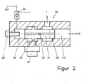
- Fig. 2 ein Absperrventil mit Ventilüberdeckung.
- Fig. 1 zeigt den grundsätzlichen Aufbau der erfindungsgemäßen Anordnung. In einem Belastungszylinder 1 ist ein Differentialkolben 2 mit einer einseitig nach außen geführten Kolbenstange 3 angeordnet. Die Kolbenstange ist in geeigneter Weise z.B. mit einem Testschlitten 5 verbunden, auf dem sich ein zu prüfendes Objekt befindet. Durch den Kolben 2 und die Kolbenstange 3 wird dem zu prüfenden Objekt eine vorgegebene Geschwindigkeit oder Beschleunigung erteilt oder es wird ein vorgegebener Weg zurückgelegt.
- Der Differentialkolben 2 weist unterschiedlich große Kolbenflächen auf, nämlich an der Kolbenstangenseite die kleine Kolbenfläche bzw. Ringfläche 2a und auf der gegenüberliegenden Seite die große Kolbenfläche bzw. Kreisfläche 2b. Von den beiden Zylinderkammern 4a, b ist die durch die kleine Kolbenfläche 2a begrenzte Zylinderkammer 4a bedingt durch die Kolbenstange ringförmig ausgebildet. Das Flächenverhältnis der Kreis- und der Ringfläche kann z.B. 2:1 betragen. Es können jedoch auch andere Flächenverhältnisse vorgesehen werden.
- Am Belastungszylinder 1 ist ein hydraulischer Druckspeicher 1o bekannter Art, z.B. ein Kolbenspeicher, Blasenspeicher oder ein anderes hydraulisches Speicherelement angebaut. Der Speicher dient als Druckmittelquelle zur Versorgung des Belastungszylinders mit dem erforderlichen Druckmittel bzw. Druckmittelvolumen. In der Zeichnung ist ein Kolbenspeicher mit einem Speicherkolben 11 dargestellt. Der Speicherkolben trennt die Flüssigkeitsseite des Speichers von der Gasseite. Wenn das Gasvolumen 12, wie in der Zeichnung angedeutet, groß gewählt wird, läßt sich ein fast konstanter Vesorgungsdruck unabhängig vom Füllungsstand des Speichers erreichen. Der hydraulische Druckspeicher lo ist über eine Verbindungsleitung 13 direkt mit der Zylinderkammer 4a (Ringkammer) verbunden. Absperrelemente in der Verbindungsleitung sind nicht vorhanden, sie können jedoch vorgesehen werden, um den Druckspeicher vom Belastungszylinder zu trennen. Mit der Zylinderkammer 4b ist der Druckspeicher über ein steuerbares oder regelbares Absperrventil 2o verbunden. An der Verbindungsleitung 13 ist eine weitere Leitung/angeschlossen, durch die der Belastungszylinder und der Druckspeicher über die Druckmittelpumpe 15 mit Drucköl aus einem Druckmittelvorratsbehälter 16 gefüllt werden. Die Druckmittelpumpe 15 kann auch so ausgelegt werden, daß sie zur Betätigung des Belastungszylinders 1 verwendbar ist. Die Art und Größe des Druckspeichers lo in der Verbindungsleitung 13 bzw. 14 kann in diesem Fall so gewählt werden, daß Druckschwankungen bei der Druckmittelzufuhr ausgeglichen werden.
- Die Verbindungsleitung 13 mündet mit Abstand vom Ende der Ringkammer 4a bzw. der Zylinderbohrung in die Kammer ein. Wenn der Kolben 2 im Betrieb die Einmündung passiert, wird die Verbindung zwischen der Zylinderkammer und der Verbindungsleitung 13 unterbrochen. Das in der Zylinderkammer 4a verbleibende Druckmittel kann nicht mehr abfließen und wirkt jetzt dämpfend auf die Bewegung des Kolbens 2 (Endlagendämpfung).
- Die Zylinderkammer 4b ist über eine Drossel 17 mit dem Druckmittelvorratsbehälter 16 verbunden. Die Drossel ist so eingstellt, daß sich in der Zylinderkammer 4b, insbesondere bei der linken Endstellung des Kolbens 2, praktisch kein Druck aufbauen kann, wenn das Absperrventil 2o geschlossen ist.
- Das Absperrventil 2o weist einen Ventilschieber 21 mit einem Betätigungskolben 22 auf. Der Betätigungskolben kann z.B. über ein kleines Servoventil 23 mit einem Druckmittel beaufschlagt werden. Damit kann der Öffnungsweg des Ventilschiebers 21 und damit die Druckmittelzufuhr vom Druckspeicher 1o zur Zylinderkammer 4b gesteuert oder geregelt werden. Der Ventilschieber 21 kann, wie in der Zeichnug angedeutet, mit einer Durchgangsbohrung 24 versehen und damit als entlasteter Schieber ausgebildet sein.
- Das Absperrventil 2o kann wie dargestellt mit dem Belastungszylinder 1 zusammengebaut sein. Das Ventil kann jedoch auch getrennt vom Belastungszylinder angeordnet werden. Die Steuer- und Regeleinrichtung für das Absperrventil 2o bzw. das Servoventil 23 ist im einzelnen nicht dargestellt.
- Zum Betrieb des Belastungszylinders wird zunächst der Druckspeicher lo mit der angeschlossenen Zylinderkammer 4a über die Leitung 14 durch die Pumpe 15 mit Druckmittel gefüllt. Der Kolben 2 befindet sich hierbei in der linken Ausgangsstellung (Fig. 1) und liegt an einem Anschlag 6 an. Durch Betätigung des Absperrventils 2o wird der Zylinderkammer 4b Druckmittel zugeführt. Am Kolben 2 wirkt jetzt eine Kraft, die sich ergibt aus dem Öldruck und der Differenz der beiden Kolbenflächen 2a und 2b. Der Kolben 2 und die Kolbenstange 3 mit dem angeschlossenen Testschlitten 5 bewegen sich in der gewünschten Weise mit einer vorgegebenen Geschwindigkeit oder Beschleunigung oder einem vorgegebenen Weg wie durch Pfeil angedeutet nach rechts.
- Wenn das Absperrventil 2o geschlossen wird, fährt der Kolben 2, bedingt durch den in der Zylinderkammer 4a herrshenden Druck, selbsttätig in seine linke Ausgangsstellung zurück. Das in der Zylinderkammer 4b befindliche Druckmittel kann hierbei langsam durch die Drossel 17 in den Voiratsbehälter 16 zurückfließen.
- Das in Fig. 2 dargestellte Absperrventil 3o mit Ventilüberdeckung weist einen Ventilschieber 31 auf, der nicht auf einem Ventilsitz aufliegt, sondern in einer Ventilbohrung 33 gleitet. Im Ventilschieber ist eine Drosselbohrung 34 angeordnet, durch die Druckmittel vom Speicher oder einer Druckmittelquelle in den Ventilraum 35 gelangen kann. Der Ventilraum 35 kann über ein Rückschlagventil 36 von außen entlastet bzw. geöffnet werden. Am Absperrventil 3o ist weiterhin ein Schaltventil 37 angebaut, mit dem der Betätigungskolben 32 des Ventilschiebers 31 beaufschlagt werden kann. In den Ventilraum 35 ragt ein einstellbarer Anschlag 38 für die Begrenzung des Ventilschieberweges (Hubbegrenzung)
- In der rechten Ausgangsstellung des Ventilschiebers 31 sperrt das Ventil den Durchfluß vom Speicher lo zum Belastungszylinder 1 ab. Bei Öffnung des Rückschlagventils 36 von außen, wird der Ventilraum 35 drucklos und dr Ventilschieber 31 beginnt sich nach links zu bewegen. Hierbei bleibt das Ventil zunächst jedoch geschlossen. Erst wenn der Schieber die Steuerkante 39 erreicht hat, öffnet das Ventil. Zu diesem Zeitpunkt hat der Ventilschieber bereits eine bestimmte Öffnungsgeschwindigkeit erreicht, so daß der Ventilquerschnitt jetzt besonders schnell freigegeben wird. Die Öffnungszeiten liegen hierbei im Bereich von Millisekunden. Die Öffnungsgeschwindigkeit des Ventilschiebers 31 kann durch die Beaufschlagung des Betätigungskolbens 32 mit einem Druckmittel über das Schaltventil 37 noch erhöht werden.
- Nach Beendung eines Prüfvorganges wird das Rückschlagventil 36 wieder geschlossen. über das Schaltventil 37 wird der Betätigungskolben 32 des Ventilschiebers mit einem Druckmittel beaufschlagt und das Absperrventil 3o wieder in Schließstellung gebracht.
- Das in Fig. 1 dargestellte Absperrventil 2o kann durch ein geeignetes Steuerventil ersetzt werden, mit dem sowohl Druckmittel in den Zylinderraum 4b zugeführt als auch aus dem Zylinderraum abgeführt werden kann. Die Drossel 17 wird in diesem Fall geschlossen bzw. entfällt. Mit einem solchen Steuerventil ist es möglich, den Belastungszylinder 1 mit dem Differentialkolben 2 als sogenannten Gleichlaufzylinder zu verwenden, d.h. als Zylinder, der in Zugrichtung und in Druckrichtung gleiche Kräfte erzeugt bzw. gleich wirkt. Das Verhältnis der Kolbenflächen 2b:2a wird in diesem Fall zweckmäßig 2:1 gewählt, d.h. der Kolben wird so ausgebildet, daß die Kreiskolbenfläche 2b doppelt so groß ist wie die Ringkolbenfläche 2a. Die Druckmittelversorgung erfolgt z.B. über eine zweckmäßig ausgelegte Druckmittelpumpe 15, wobei in der Verwendungsleitung 13, 14 zwischen Pumpe 15 und Belastungszylinder 1 ein geeigneter Druckspeicher lo zum Ausgleich von Druckschwankungen angeordnet sein kann.
- In der Zylinderkammer 4a herrscht ständig der Systemdruck bzw. der von der Druckmittelpumpe 15 erzeugte Maximaldruck. In der Zylinderkammer 4b kann der Druck je nach Ansteuerung des Steuerventils zwischen Null und dem Maximaldruck liegen. Herrscht in der Zylinderkammer 4b Maximaldruck, so bewegt sich der Kolben im dargestellten Ausführungsbeispiel nach rechts bzw. erzeugt eine nach rechts gerichtete Kraft, da die Kolbenfläche 2b doppelt so groß ist wie die Kolbenfläche 2a und in beiden Kammern gleicher Druck herrscht. Die Kolbenkraft ergibt sich aus dem System- bzw. Maximaldruck und aus der Differenz der Kolbenflächen 2b und 2a. Wenn sich der Kolben in Fig. 1 nach rechts bewegt, wird cbs Druckmittel in der Zylinderkammer 4a lediglich in die Zylinderkammer 4b umgepumpt.
- Bei Druck Null in der Zylinderkammer 4b bewegt sich der Kolben nach links, bzw. es entsteht am Kolben und an der Kolbenstange eine nach links gerichtete Kraft, da jetzt nur der Druck in der Zylinderkammer 4a wirkt. Der Druck in der Zylinderkammer 4b und damit die Kolbenbewegung bzw. die Kolbenkraft in beiden Bewegungsrichtungen kann durch entsprechende Ansteuerung des Steuerventils beliebig gesteuert werden. Durch die erfindungsgemäße Anordnung kann also mit einem Differentialzylinder die gleiche Kraft in beiden Bewegungsrichtungen des Kolbens ausgeübt werden. Als Steuerventil kann z.B. ein Mehrwegeventil oder ein Servoventil verwendet werden.
Claims (10)
Priority Applications (3)
| Application Number | Priority Date | Filing Date | Title |
|---|---|---|---|
| DE8181109849T DE3174211D1 (en) | 1981-11-24 | 1981-11-24 | Hydraulic loading device, especially for catapult systems |
| EP81109849A EP0079979B1 (de) | 1981-11-24 | 1981-11-24 | Hydraulische Belastungsvorrichtung, insbesondere für Katapultanlagen |
| JP57104086A JPS5894603A (ja) | 1981-11-24 | 1982-06-18 | 特にカタパルト装置用の液圧式荷重シリンダ |
Applications Claiming Priority (1)
| Application Number | Priority Date | Filing Date | Title |
|---|---|---|---|
| EP81109849A EP0079979B1 (de) | 1981-11-24 | 1981-11-24 | Hydraulische Belastungsvorrichtung, insbesondere für Katapultanlagen |
Publications (2)
| Publication Number | Publication Date |
|---|---|
| EP0079979A1 true EP0079979A1 (de) | 1983-06-01 |
| EP0079979B1 EP0079979B1 (de) | 1986-03-26 |
Family
ID=8188028
Family Applications (1)
| Application Number | Title | Priority Date | Filing Date |
|---|---|---|---|
| EP81109849A Expired EP0079979B1 (de) | 1981-11-24 | 1981-11-24 | Hydraulische Belastungsvorrichtung, insbesondere für Katapultanlagen |
Country Status (3)
| Country | Link |
|---|---|
| EP (1) | EP0079979B1 (de) |
| JP (1) | JPS5894603A (de) |
| DE (1) | DE3174211D1 (de) |
Cited By (2)
| Publication number | Priority date | Publication date | Assignee | Title |
|---|---|---|---|---|
| EP0225397A1 (de) * | 1985-12-13 | 1987-06-16 | Carl Schenck Ag | Verfahren und Vorrichtung zur Erzeugung von stossartigen Belastungen an einem Prüfling |
| EP0326070A3 (de) * | 1988-01-28 | 1990-09-12 | Poly Id Ag | Hydraulischer Antrieb für Schlagzug- und Durchstossversuche |
Citations (5)
| Publication number | Priority date | Publication date | Assignee | Title |
|---|---|---|---|---|
| FR559284A (fr) * | 1922-01-19 | 1923-09-12 | Buehler Ag Geb | Piston différentiel pour cylindres hydrauliques |
| FR1399512A (fr) * | 1964-06-26 | 1965-05-14 | Bergwerksverband Gmbh | Procédé et dispositif pour la détermination de la charge limite d'éléments de construction hydrauliques, notamment de tuyaux flexibles sous pression |
| FR2120217A5 (de) * | 1970-09-24 | 1972-08-18 | Delbergue Martial | |
| GB2034008A (en) * | 1978-10-30 | 1980-05-29 | Mts System Corp | Control valve |
| GB2034443A (en) * | 1978-10-30 | 1980-06-04 | Mts System Corp | High flow rate hydraulic control valve |
Family Cites Families (1)
| Publication number | Priority date | Publication date | Assignee | Title |
|---|---|---|---|---|
| JPS54147378A (en) * | 1978-05-10 | 1979-11-17 | Toyooki Kogyo Co Ltd | High speed cylinder device |
-
1981
- 1981-11-24 DE DE8181109849T patent/DE3174211D1/de not_active Expired
- 1981-11-24 EP EP81109849A patent/EP0079979B1/de not_active Expired
-
1982
- 1982-06-18 JP JP57104086A patent/JPS5894603A/ja active Pending
Patent Citations (5)
| Publication number | Priority date | Publication date | Assignee | Title |
|---|---|---|---|---|
| FR559284A (fr) * | 1922-01-19 | 1923-09-12 | Buehler Ag Geb | Piston différentiel pour cylindres hydrauliques |
| FR1399512A (fr) * | 1964-06-26 | 1965-05-14 | Bergwerksverband Gmbh | Procédé et dispositif pour la détermination de la charge limite d'éléments de construction hydrauliques, notamment de tuyaux flexibles sous pression |
| FR2120217A5 (de) * | 1970-09-24 | 1972-08-18 | Delbergue Martial | |
| GB2034008A (en) * | 1978-10-30 | 1980-05-29 | Mts System Corp | Control valve |
| GB2034443A (en) * | 1978-10-30 | 1980-06-04 | Mts System Corp | High flow rate hydraulic control valve |
Cited By (2)
| Publication number | Priority date | Publication date | Assignee | Title |
|---|---|---|---|---|
| EP0225397A1 (de) * | 1985-12-13 | 1987-06-16 | Carl Schenck Ag | Verfahren und Vorrichtung zur Erzeugung von stossartigen Belastungen an einem Prüfling |
| EP0326070A3 (de) * | 1988-01-28 | 1990-09-12 | Poly Id Ag | Hydraulischer Antrieb für Schlagzug- und Durchstossversuche |
Also Published As
| Publication number | Publication date |
|---|---|
| JPS5894603A (ja) | 1983-06-04 |
| EP0079979B1 (de) | 1986-03-26 |
| DE3174211D1 (en) | 1986-04-30 |
Similar Documents
| Publication | Publication Date | Title |
|---|---|---|
| DE2305798A1 (de) | Hydraulische steuereinrichtung, insbesondere lenkeinrichtung | |
| DE2305835A1 (de) | Hydraulische steuereinrichtung, insbesondere lenkeinrichtung | |
| DE69011280T2 (de) | Hydraulische antriebsanordnung einer bauvorrichtung. | |
| DE2124620B2 (de) | Elektrisch fernsteuerbares druckbegrenzungsventil | |
| DE1951429A1 (de) | Hydraulisches Versorgungssystem | |
| CH628117A5 (en) | Brake-valve device | |
| DE2349620C2 (de) | Fernsteuersystem für eine hydraulische Leistungsübertragungsvorrichtung | |
| EP0079979B1 (de) | Hydraulische Belastungsvorrichtung, insbesondere für Katapultanlagen | |
| DE1298801B (de) | Hydraulischer Dreiwege-Stromregler | |
| DE3127927A1 (de) | Druckregelventil fuer fluessigkeiten | |
| DE2104362A1 (de) | Druckventil fuer hydraulische anlagen | |
| DE2038813C2 (de) | Druckmittelbetätigtes Mehrwegeventil in Schieberbauart | |
| DE2502854A1 (de) | Kolbenschiebersteuervorrichtung | |
| DE2043337B2 (de) | Hydraulisches Servoventil | |
| DE4120489A1 (de) | Niveauregeleinrichtung fuer fahrzeuge | |
| DE3619044A1 (de) | Drucksteuereinrichtung fuer einen hydraulischen verbraucher | |
| DE2826613C2 (de) | Stromregelventil | |
| DE1550625A1 (de) | Selbsttaetiges Steuerventil fuer Hydraulikanlagen,insbesondere fuer Kraftfahrzeuge | |
| DE2827128A1 (de) | Kompaktes, vorgesteuertes druckbegrenzungsventil | |
| DE3146322A1 (de) | Steuerventileinrichtung fuer einen hydraulischen verbraucher | |
| DE1426584C3 (de) | Steuereinrichtung für einen doppelt wirkenden Arbeitszylinder | |
| DE1183789B (de) | Fluessigkeitsteilerventil fuer Druckmittelanlagen mit mehreren Verbrauchern | |
| DE1083657B (de) | Steuereinrichtung fuer hydraulische Servoeinrichtungen | |
| DE2703999A1 (de) | Schieberventil | |
| DD220886A1 (de) | Anordnung zur druckregelung in hydraulischen kreislaeufen |
Legal Events
| Date | Code | Title | Description |
|---|---|---|---|
| PUAI | Public reference made under article 153(3) epc to a published international application that has entered the european phase |
Free format text: ORIGINAL CODE: 0009012 |
|
| AK | Designated contracting states |
Designated state(s): CH DE GB LI |
|
| RBV | Designated contracting states (corrected) |
Designated state(s): CH DE GB LI |
|
| 17P | Request for examination filed |
Effective date: 19831001 |
|
| GRAA | (expected) grant |
Free format text: ORIGINAL CODE: 0009210 |
|
| AK | Designated contracting states |
Kind code of ref document: B1 Designated state(s): CH DE GB LI |
|
| REF | Corresponds to: |
Ref document number: 3174211 Country of ref document: DE Date of ref document: 19860430 |
|
| PLBI | Opposition filed |
Free format text: ORIGINAL CODE: 0009260 |
|
| 26 | Opposition filed |
Opponent name: MANNESMANN REXROTH GMBH Effective date: 19861113 |
|
| RDAG | Patent revoked |
Free format text: ORIGINAL CODE: 0009271 |
|
| STAA | Information on the status of an ep patent application or granted ep patent |
Free format text: STATUS: PATENT REVOKED |
|
| GBPR | Gb: patent revoked under art. 102 of the ep convention designating the uk as contracting state | ||
| 27W | Patent revoked |
Effective date: 19880528 |
|
| REG | Reference to a national code |
Ref country code: CH Ref legal event code: PL |