EP0079992A1 - Vorrichtung zum Trocknen von Geweben - Google Patents
Vorrichtung zum Trocknen von Geweben Download PDFInfo
- Publication number
- EP0079992A1 EP0079992A1 EP81305521A EP81305521A EP0079992A1 EP 0079992 A1 EP0079992 A1 EP 0079992A1 EP 81305521 A EP81305521 A EP 81305521A EP 81305521 A EP81305521 A EP 81305521A EP 0079992 A1 EP0079992 A1 EP 0079992A1
- Authority
- EP
- European Patent Office
- Prior art keywords
- stenter
- fabric
- chamber
- openings
- wetted
- Prior art date
- Legal status (The legal status is an assumption and is not a legal conclusion. Google has not performed a legal analysis and makes no representation as to the accuracy of the status listed.)
- Granted
Links
- 239000004744 fabric Substances 0.000 title claims abstract description 41
- 238000001035 drying Methods 0.000 title claims abstract description 8
- 239000004753 textile Substances 0.000 title claims abstract description 7
- 238000000034 method Methods 0.000 claims abstract description 6
- 230000008569 process Effects 0.000 claims abstract description 6
- 238000001704 evaporation Methods 0.000 claims description 5
- 230000008020 evaporation Effects 0.000 claims description 4
- 230000007246 mechanism Effects 0.000 description 5
- 230000008859 change Effects 0.000 description 4
- 239000010410 layer Substances 0.000 description 2
- 239000002356 single layer Substances 0.000 description 2
- 238000009833 condensation Methods 0.000 description 1
- 230000005494 condensation Effects 0.000 description 1
- 238000010924 continuous production Methods 0.000 description 1
- 238000010981 drying operation Methods 0.000 description 1
- 238000010438 heat treatment Methods 0.000 description 1
- 238000002347 injection Methods 0.000 description 1
- 239000007924 injection Substances 0.000 description 1
- 238000004519 manufacturing process Methods 0.000 description 1
- 238000004383 yellowing Methods 0.000 description 1
Images


Classifications
-
- D—TEXTILES; PAPER
- D06—TREATMENT OF TEXTILES OR THE LIKE; LAUNDERING; FLEXIBLE MATERIALS NOT OTHERWISE PROVIDED FOR
- D06C—FINISHING, DRESSING, TENTERING OR STRETCHING TEXTILE FABRICS
- D06C3/00—Stretching, tentering or spreading textile fabrics; Producing elasticity in textile fabrics
- D06C3/02—Stretching, tentering or spreading textile fabrics; Producing elasticity in textile fabrics by endless chain or like apparatus
-
- F—MECHANICAL ENGINEERING; LIGHTING; HEATING; WEAPONS; BLASTING
- F26—DRYING
- F26B—DRYING SOLID MATERIALS OR OBJECTS BY REMOVING LIQUID THEREFROM
- F26B13/00—Machines and apparatus for drying fabrics, fibres, yarns, or other materials in long lengths, with progressive movement
- F26B13/10—Arrangements for feeding, heating or supporting materials; Controlling movement, tension or position of materials
Definitions
- This invention relates to a process for drying wet textile fabrics in a stenter or float-dryer and improvements in or relating to a stenter or float-dryer adapted to carry out the process.
- stenter includes a single layer stenter, a multi-layer stenter and a float-dryer
- the word “chamber” includes a plurality of chambers.
- a stenter could be defined as a machine essentially comprising (i) a mechanism to feed continuously a wetted textile fabric into a chamber in which (ii) processes such as equalising, finishing or curing are carried out on the moving fabric while it is being simultaneously dried, and (iii) a mechanism for delivering from said chamber dried processed fabric.
- a stenter in current use employs dry air as the evaporating medium in its chamber. Good results could be obtained if the drying medium is moistureless air but that is never possible because the drying operation on wetted fabric must produce vapour and the air in the chamber can never be completely dry. However, it has been ascertained that the optimum ratio of air to moisture in the medium circulating in the chamber should be 9:1 by weight. Since evaporation is a continuous process, the said ratio will be fluctuating and in course of time, it is bound to fall below the optimum. It then becomes necessary to exhaust some of the medium from the chamber. As a result of the partial exhausting of the medium, a slight vacuum is created resulting in the sucking in of fresh air from gaps at the entry and exit of the fabric into and from the chamber. The fresh air has to be raised to the temperature of 150° C. The temperature of the exhausted medium is around 130° C. There is thus a distinct loss and expenditure of heat energy.
- a process for drying wetted textile fabric of the kind which comprises passing the wetted fabric through a stenter is characterised in that as the wetted fabric passes through the stenter it is subjected to superheated steam at a temperature of about 150° C., the superheated steam being generated by evaperation of the moisture in the wetted fabric.
- the chamber design has to be modified because of the change of medium from hot air to superheated steam.
- the known current stenter has a chamber provided with longitudinally aligned heat radiators, each radiator being located in the vicinity of a linear plurality of suction fans, each fan being located in a circular fan-housing opening into a tapering rectangular tunnel with openings in its side facing the moving fabric.
- the openings are a plurality of holes.
- This invention provides discharge of superheated steam by transverse widthwise jets upon the moving fabric by means of venturi openings running along the sides of each housing, the inner walls of the venturi openings being adapted to form a channel for the return of the steam reflected from the surface of the fabric to the space in the vicinity of the radiators, the steam entering the tunnel being guided into the venturi openings by means of parallelly disposed pendant inclined slats transverse to the venturi openings.
- the exhaust is located in the top of the chamber. This position of the exhaust is not desirable when the drying medium is changed from air to superheated steam. Being lighter than air, the steam tends to rise to the top of the chamber leaving some air at the bottom. Furthermore, the medium in the chamber contains the vapour of oil or wax used in finishing the fabric, the condensation of which near the exhaust in the top of the chamber would produce droplets which might fall on the running fabric and damage it.
- This invention therefore, provides an exhaust opening or openings in the bottom of the chamber.
- the bottom location of the exhaust openings ensure the complete removal of air from the chamber.
- This invention accordingly provides each of the exhaust openings with a damper adapted to operate only when the pressure inside the chamber exceeds the safety. level.
- the damper is actuated,by a mechanism which is in turn actuated by a signal from a photoelectric cell which becomes activated only when the level in a manometer limb connected to the chamber goes down beyond the safety level.
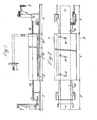
- 1 indicates the fabric sheet passing through the chamber Y.
- la indicates the wet fabric entering the chamber Y 1b the dry processed fabric delivered from the chamber Y and 9 indicates the vertical section of the walls of the chamber Y along the sectional line AB.
- the chamber has an exhaust opening 8 at its bottom.
- the fabric 1 is partially dry after its passage from the entry to the line AB. It is being further dried by superheated steam which is made to circulate in the chamber Y by means of fans 2 and 3 located inside the fan-housings 4.1 and 5.1 and the truncated tunnels 4.2 and 5.2 respectively.
- the tunnels have the openings 10 facing the fabric 1.
- the vapour produced by the evaporation of the moisture in the fabric 1 and the steam reflected from the fabric 1 proceed to the space surrounding the radiators 6 and 7 located in the chamber Y near its walls 9.1 and 9.2 respectively.
- the fans 2 and 3 are located below and above the radiators 7 and 6 respectively.
- the arrows in Figure 7 show the direction of the circulation of the medium.
- Figure 8 is a duplication of Figure 7 with this difference that the fabric 1 is moving in the opposite directions in the upper and lower halves of the figure.
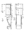
- 10 indicates the linear venturi openings in the tunnel 4.2 or 5.2 with the channel 11 between them. Immediately below the channel 11 are a series of parallel pendant slats 12.
- a manometer 13 is connected to the chamber Y.
- the arrows 14 indicate the position of a photoelectric cell.
- a signal from the photoelectric cell actuates the motorized drive 15 of the damper 16 in the exhaust opening 8.
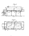
- the wetted fabric la is fed into the chamber Y where it is dried by superheated steam produced by the heating elements or radiators 6 and 7.
- the superheated steam is sucked in by the fans 2 and 3 through the opening in the fan housings 4.1 and 5.1 and pushed into the tunnels 4.2 and 5.2 from where the superheated.
Landscapes
- Engineering & Computer Science (AREA)
- Textile Engineering (AREA)
- Mechanical Engineering (AREA)
- General Engineering & Computer Science (AREA)
- Treatment Of Fiber Materials (AREA)
- Drying Of Solid Materials (AREA)
Priority Applications (2)
| Application Number | Priority Date | Filing Date | Title |
|---|---|---|---|
| EP19810305521 EP0079992B1 (de) | 1981-11-23 | 1981-11-23 | Vorrichtung zum Trocknen von Geweben |
| DE8181305521T DE3176638D1 (en) | 1981-11-23 | 1981-11-23 | Apparatus for drying wet textile fabrics |
Applications Claiming Priority (1)
| Application Number | Priority Date | Filing Date | Title |
|---|---|---|---|
| EP19810305521 EP0079992B1 (de) | 1981-11-23 | 1981-11-23 | Vorrichtung zum Trocknen von Geweben |
Publications (2)
| Publication Number | Publication Date |
|---|---|
| EP0079992A1 true EP0079992A1 (de) | 1983-06-01 |
| EP0079992B1 EP0079992B1 (de) | 1988-02-03 |
Family
ID=8188460
Family Applications (1)
| Application Number | Title | Priority Date | Filing Date |
|---|---|---|---|
| EP19810305521 Expired EP0079992B1 (de) | 1981-11-23 | 1981-11-23 | Vorrichtung zum Trocknen von Geweben |
Country Status (2)
| Country | Link |
|---|---|
| EP (1) | EP0079992B1 (de) |
| DE (1) | DE3176638D1 (de) |
Cited By (2)
| Publication number | Priority date | Publication date | Assignee | Title |
|---|---|---|---|---|
| CN105066617A (zh) * | 2015-08-14 | 2015-11-18 | 吴江金叶织造有限公司 | 一种设有拉幅机构的布铗链式热风烘干机 |
| CN114812140A (zh) * | 2022-05-11 | 2022-07-29 | 徐亿强 | 一种具有自动输送功能的纺织烘干装置 |
Citations (6)
| Publication number | Priority date | Publication date | Assignee | Title |
|---|---|---|---|---|
| FR1224122A (fr) * | 1959-01-14 | 1960-06-22 | Alsacienne Constr Meca | Installation de vaporisage de tissus |
| US3015893A (en) * | 1960-03-14 | 1962-01-09 | Mccreary John | Fluid flow control device for tenter machines utilizing super-heated steam |
| US3408748A (en) * | 1966-08-17 | 1968-11-05 | Dow Chemical Co | Drying and recovery process |
| US3510954A (en) * | 1968-04-10 | 1970-05-12 | Dow Chemical Co | Solvent removal |
| US3798785A (en) * | 1970-09-22 | 1974-03-26 | D Chamouton | Device for drying continuous web material |
| GB2063442A (en) * | 1979-11-07 | 1981-06-03 | Weber R | Drying Textiles |
-
1981
- 1981-11-23 DE DE8181305521T patent/DE3176638D1/de not_active Expired
- 1981-11-23 EP EP19810305521 patent/EP0079992B1/de not_active Expired
Patent Citations (6)
| Publication number | Priority date | Publication date | Assignee | Title |
|---|---|---|---|---|
| FR1224122A (fr) * | 1959-01-14 | 1960-06-22 | Alsacienne Constr Meca | Installation de vaporisage de tissus |
| US3015893A (en) * | 1960-03-14 | 1962-01-09 | Mccreary John | Fluid flow control device for tenter machines utilizing super-heated steam |
| US3408748A (en) * | 1966-08-17 | 1968-11-05 | Dow Chemical Co | Drying and recovery process |
| US3510954A (en) * | 1968-04-10 | 1970-05-12 | Dow Chemical Co | Solvent removal |
| US3798785A (en) * | 1970-09-22 | 1974-03-26 | D Chamouton | Device for drying continuous web material |
| GB2063442A (en) * | 1979-11-07 | 1981-06-03 | Weber R | Drying Textiles |
Cited By (2)
| Publication number | Priority date | Publication date | Assignee | Title |
|---|---|---|---|---|
| CN105066617A (zh) * | 2015-08-14 | 2015-11-18 | 吴江金叶织造有限公司 | 一种设有拉幅机构的布铗链式热风烘干机 |
| CN114812140A (zh) * | 2022-05-11 | 2022-07-29 | 徐亿强 | 一种具有自动输送功能的纺织烘干装置 |
Also Published As
| Publication number | Publication date |
|---|---|
| EP0079992B1 (de) | 1988-02-03 |
| DE3176638D1 (en) | 1988-03-10 |
Similar Documents
| Publication | Publication Date | Title |
|---|---|---|
| US4467537A (en) | Equipment for heat-treating flat, band-like lengths of material | |
| JPH01503136A (ja) | セラミック中空体の乾燥方法及びその装置 | |
| US4106215A (en) | Wood impingement dryer | |
| GB2045410A (en) | Float-drier | |
| US4777734A (en) | Method and an apparatus for drying eggs, fruits or the like articles | |
| US20070107256A1 (en) | Device and method for drying a treated product | |
| JP2002544468A (ja) | 帯状または板状の被乾燥物のための乾燥機 | |
| US5396716A (en) | Jet tube dryer with independently controllable modules | |
| KR100272749B1 (ko) | 직물 피륙용 송풍장치 | |
| US4116756A (en) | Spray drying on woven belt of monofilament synthetic fiber | |
| EP0079992A1 (de) | Vorrichtung zum Trocknen von Geweben | |
| EP0269358A2 (de) | Trocknungs- oder Backvorrichtung | |
| US4439930A (en) | Conveyor dryer and method of operation | |
| US4011663A (en) | Apparatus for drying fabrics | |
| GB2088426A (en) | Drying wet textile fabrics | |
| US3758960A (en) | Apparatus for drying materials | |
| US3430352A (en) | Method and apparatus for the heat-treatment of materials which can be stressed in a longitudinal direction | |
| US3686903A (en) | Apparatus for the contact-free treatment of materials which can be stressed in a lengthwise direction | |
| US3512265A (en) | Process and apparatus for the contac-tfree treatment of materials which can be stressed in a lengthwise direction | |
| US2722752A (en) | Drying plants for wooden sheet material | |
| US4215489A (en) | Roller dryer | |
| WO1979000800A1 (en) | Vapor exchange | |
| US3376653A (en) | Dryer ventilation | |
| US2641119A (en) | Ageing or reducing apparatus | |
| US1472741A (en) | Drier |
Legal Events
| Date | Code | Title | Description |
|---|---|---|---|
| PUAI | Public reference made under article 153(3) epc to a published international application that has entered the european phase |
Free format text: ORIGINAL CODE: 0009012 |
|
| AK | Designated contracting states |
Designated state(s): CH DE FR IT LI NL |
|
| 17P | Request for examination filed |
Effective date: 19831110 |
|
| ITF | It: translation for a ep patent filed | ||
| GRAA | (expected) grant |
Free format text: ORIGINAL CODE: 0009210 |
|
| AK | Designated contracting states |
Kind code of ref document: B1 Designated state(s): CH DE FR IT LI NL |
|
| REF | Corresponds to: |
Ref document number: 3176638 Country of ref document: DE Date of ref document: 19880310 |
|
| ET | Fr: translation filed | ||
| PG25 | Lapsed in a contracting state [announced via postgrant information from national office to epo] |
Ref country code: LI Effective date: 19881130 Ref country code: CH Effective date: 19881130 |
|
| PLBE | No opposition filed within time limit |
Free format text: ORIGINAL CODE: 0009261 |
|
| STAA | Information on the status of an ep patent application or granted ep patent |
Free format text: STATUS: NO OPPOSITION FILED WITHIN TIME LIMIT |
|
| 26N | No opposition filed | ||
| PG25 | Lapsed in a contracting state [announced via postgrant information from national office to epo] |
Ref country code: NL Effective date: 19890601 |
|
| NLV4 | Nl: lapsed or anulled due to non-payment of the annual fee | ||
| PG25 | Lapsed in a contracting state [announced via postgrant information from national office to epo] |
Ref country code: FR Free format text: LAPSE BECAUSE OF NON-PAYMENT OF DUE FEES Effective date: 19890731 |
|
| REG | Reference to a national code |
Ref country code: CH Ref legal event code: PL |
|
| PG25 | Lapsed in a contracting state [announced via postgrant information from national office to epo] |
Ref country code: DE Effective date: 19890801 |
|
| REG | Reference to a national code |
Ref country code: FR Ref legal event code: ST |