EP0080025B1 - Dispositif d'indication continue, particulièrement un tachymètre - Google Patents
Dispositif d'indication continue, particulièrement un tachymètre Download PDFInfo
- Publication number
- EP0080025B1 EP0080025B1 EP82107422A EP82107422A EP0080025B1 EP 0080025 B1 EP0080025 B1 EP 0080025B1 EP 82107422 A EP82107422 A EP 82107422A EP 82107422 A EP82107422 A EP 82107422A EP 0080025 B1 EP0080025 B1 EP 0080025B1
- Authority
- EP
- European Patent Office
- Prior art keywords
- frequency
- pointer
- stop
- pulse
- stepping motor
- Prior art date
- Legal status (The legal status is an assumption and is not a legal conclusion. Google has not performed a legal analysis and makes no representation as to the accuracy of the status listed.)
- Expired
Links
Images
Classifications
-
- G—PHYSICS
- G01—MEASURING; TESTING
- G01D—MEASURING NOT SPECIALLY ADAPTED FOR A SPECIFIC VARIABLE; ARRANGEMENTS FOR MEASURING TWO OR MORE VARIABLES NOT COVERED IN A SINGLE OTHER SUBCLASS; TARIFF METERING APPARATUS; MEASURING OR TESTING NOT OTHERWISE PROVIDED FOR
- G01D11/00—Component parts of measuring arrangements not specially adapted for a specific variable
- G01D11/16—Elements for restraining, or preventing the movement of, parts, e.g. for zeroising
-
- G—PHYSICS
- G01—MEASURING; TESTING
- G01P—MEASURING LINEAR OR ANGULAR SPEED, ACCELERATION, DECELERATION, OR SHOCK; INDICATING PRESENCE, ABSENCE, OR DIRECTION, OF MOVEMENT
- G01P1/00—Details of instruments
- G01P1/04—Special adaptations of driving means
Definitions
- the invention relates to an analog display device, in particular a tachometer according to the preamble of claim 1.
- the tachometer mentioned here is a so-called electronic tachometer, in which a pulse frequency proportional to the speed of the vehicle is evaluated, by means of a stepper motor, a pointer or to adjust a speedometer needle.
- the analog display device of the type mentioned above is not limited to electronic tachometers, but generally relates to a display device for state variables that are to be displayed in analog form.
- a pointer is deflected by a reversible stepper motor via a gear.
- a gear wheel of the transmission on the axis of which the pointer is mounted, has an approximately semicircular cutout into which a stop pin extends. This stop pin limits the pointer deflection in the zero position and in the end deflection position.
- the stepper motor is fed by a pulse organizer with a preparation input via a stepper motor control circuit.
- the pulse generator also feeds an up-down counter, the outputs of which are connected to a comparison circuit.
- the comparison circuit is connected to measured value inputs into which signals corresponding to the measured value are fed in the same digital form as the counter reading of the up-down counter is output.
- Outputs of the comparison circuit are connected on the one hand via an AND gate to an up-down control input of the up-down counter and a forward-backward control of the stepper motor control circuit and on the other hand via a second AND gate to the preparation input of the pulse generator.
- Two further inputs of said first and second AND gates are controlled by the output of a flip-flop which has a reset input for receiving a reset signal. The reset signal forms a reset command for the pulse generator in conjunction with the flip-flop.
- the up-down counter When a reset signal occurs, the up-down counter is reset to zero and the flip-flop is flipped to a position which issues a reset command to the preparation input of the pulse generator.
- the pulse generator then delivers pulses to the stepper motor as well as to the up-down counter via the stepper motor control circuit. This causes the up-down counter to count down and the stepper motor to reset the pointer step by step. This process continues until the counting capacity of the up-down counter is reached, i.e. the same number of pulses is always delivered to the stepper motor for resetting.
- the cutout in the gear wheel connected to the pointer inevitably comes into engagement with the stop pin in the zero position of the pointer, as a result of which the pointer is stopped in the zero position. In this position, the pointer and the up-down counter are synchronized with each other.
- the reset process can take place each time the analog display device is switched on or with the aid of a detector (DE-A-29 46 328).
- a disadvantage of this analog display device is that the stop in the zero position is loaded by the gear unit with a considerable torque of the stepping motor if the pointer is not reset from its full deflection but from a lower value.
- the momentum of the motor with the gearbox which further increases the load on the stop and the gearbox, so that in view of the load caused by the normal driving torque of the motor, the reset must be carried out at a limited speed if the gearbox does not have high strength properties and is constructed with a larger moment of inertia.
- the object of the present invention is therefore to further develop an analog display device of the type mentioned at the beginning with a resetting of the stepping motor with a constant number of pulses such that the load on the mechanical parts of the display device, in particular the stop and the transmission, is relatively low, and that nevertheless, the reset is quick and reliable.
- the stepper motor is initially subjected to a relatively low-frequency pulse sequence at the beginning of the reset phase, the frequency of which is below the start-stop frequency of the stepper motor, the stepper motor starts reliably and synchronously with the pulses. Only then will the pulse rate be increased to values above the start-stop rate. This not only accelerates the resetting, but the drive torque drops as the frequency increases due to the usual characteristics of the stepper motor. This has the desired consequence that the drive torque is relatively low when the stop is reached when the pointer is in the zero position. In this analog display device, the mechanical parts can therefore be designed to be relatively low-mass. Despite the accelerated reset, the synchronization between pointer position and pulse number is maintained, ie the pointer is also reliably reset from the full deflection.
- a particularly inexpensive implementation of the analog display device with the controlled pulse generator is that it is designed as a ramp generator that increases the pulse frequency from below the start-stop frequency to the maximum operating frequency of the stepper motor.
- This ramp generator also ensures a particularly reliable synchronization of the stepper motor movement with the feeding pulses.
- the pulse generator can be controlled by a voltage detector. After the normal battery voltage has been switched off, the analog display device can be supplied via another connection to the battery or by means of an auxiliary battery.
- the analog display device with a gear wheel driving the pointer which is connected to the stepper motor, is designed, for example, in such a way that the gear wheel has a cutout that is proportional to the end stop of the pointer and that forms two end stops in connection with a stationary stop pin .
- the fixed stop pin does not come into direct contact with the pointer during these stops, it is particularly suitable for resetting with a number of pulses which is greater than is necessary until the stop is reached in the zero position.
- the cutout of the gearwheel can better absorb the impulses and forces when the stop pin strikes than the pointer directly.
- a circuit for accelerating and braking a stepper motor is known.
- a function generator feeds a voltage-controlled oscillator with a ramp-like rising or falling voltage if necessary.
- the oscillator in turn feeds a pulse to the stepper motor, the frequency of which depends on the voltage supplied by the function generator, i.e. can rise and fall.
- the stepper motor delivers maximum drive torque at low speeds.
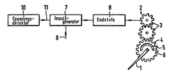
- a pulse generator 7 is controlled via a control input 8 with a speed signal in such a way that the pulse generator outputs a pulse defining the change in speed according to amount and size to an output stage 9 and from there to the stepper motor 2.
- the position of the pointer is always proportional to the speed.
- the interruption of the voltage by the ignition lock is detected by a voltage detector 10.
- the voltage detector issues a reset command in a second control input 11 of the pulse generator 7.
- This causes the pulse generator to output a constant number of pulses to the output stage 9 which is so large that the pointer is also reset to zero from the full deflection position.
- the stop pin 6 abuts the end of the cutout 5 associated with the zero position.
- this pulse is not delivered at a constant frequency, but - since the pulse generator comprises a ramp generator - in such a way that the first pulses are generated at a pulse frequency below the start-stop frequency of the stepping motor 2 and only afterwards the subsequent pulses at a pulse frequency run up above the start-stop frequency.
- the stepper motor 2 thus starts up reliably in order to be reset synchronously with the number of pulses even when the static friction torque is overcome. Only then is the speed of the reset increased, with the desired result that the drive torque of the stepper motor drops, so that the Section 5 of the gear 4 is struck against the stop pin 6 only under a relatively low engine torque. Since in most cases when the pointer is in the zero position, further pulses for resetting are emitted by the pulse generator, the pointer is held in this position, which is also desirable since the holding torque of the stepper motor is relatively low.
- the pulse frequency at which the pulses are released for resetting above the start-stop frequency should be below the maximum operating frequency of the stepper motor in order to drive the stepper motor in any case synchronously with the pulses.
Landscapes
- Physics & Mathematics (AREA)
- General Physics & Mathematics (AREA)
- Control Of Stepping Motors (AREA)
- Arrangements For Transmission Of Measured Signals (AREA)
- Indicating Measured Values (AREA)
- Instrument Panels (AREA)
Claims (3)
Applications Claiming Priority (2)
| Application Number | Priority Date | Filing Date | Title |
|---|---|---|---|
| DE3145780 | 1981-11-19 | ||
| DE19813145780 DE3145780A1 (de) | 1981-11-19 | 1981-11-19 | Analog-anzeigeeinrichtung, insbesondere tachometer |
Publications (3)
| Publication Number | Publication Date |
|---|---|
| EP0080025A2 EP0080025A2 (fr) | 1983-06-01 |
| EP0080025A3 EP0080025A3 (en) | 1985-08-21 |
| EP0080025B1 true EP0080025B1 (fr) | 1987-10-14 |
Family
ID=6146684
Family Applications (1)
| Application Number | Title | Priority Date | Filing Date |
|---|---|---|---|
| EP82107422A Expired EP0080025B1 (fr) | 1981-11-19 | 1982-08-16 | Dispositif d'indication continue, particulièrement un tachymètre |
Country Status (4)
| Country | Link |
|---|---|
| US (1) | US4475082A (fr) |
| EP (1) | EP0080025B1 (fr) |
| JP (1) | JPS5890121A (fr) |
| DE (2) | DE3145780A1 (fr) |
Families Citing this family (12)
| Publication number | Priority date | Publication date | Assignee | Title |
|---|---|---|---|---|
| US4567434A (en) * | 1981-11-19 | 1986-01-28 | Vdo Adolf Schindling Ag | Analog display device, particularly a tachometer |
| GB2184242B (en) * | 1985-11-13 | 1989-11-15 | Mitutoyo Mfg Co Ltd | Electronic measuring device |
| US4706008A (en) * | 1986-12-11 | 1987-11-10 | Ibm Corporation | Self-adjusting homing for a stepping motor |
| DE3701072C2 (de) * | 1987-01-16 | 1995-07-20 | Vdo Schindling | Zeigerinstrument |
| DE4018091A1 (de) * | 1990-06-06 | 1991-12-12 | Bosch Gmbh Robert | Untersetzungsgetriebe fuer anzeigeinstrument |
| JP2524935Y2 (ja) * | 1990-12-26 | 1997-02-05 | 矢崎総業株式会社 | 車両用表示装置 |
| DE4310060C2 (de) * | 1992-03-28 | 1996-06-13 | Noris Tachometerwerk | Elektrisches Analog-Anzeigeinstrument mit Rückstelleinrichtung |
| DE4403620B4 (de) * | 1994-02-05 | 2008-04-10 | Siemens Ag | Zeigerinstrument |
| JP3048113B2 (ja) * | 1995-01-11 | 2000-06-05 | 矢崎総業株式会社 | 針式表示装置及び針式表示装置用指針の原点復帰方法 |
| FR2732836B1 (fr) * | 1995-04-07 | 1997-06-20 | Magneti Marelli France | Systeme d'entrainement a base de moteur pas a pas comprenant des moyens perfectionnes de remise a zero |
| ES2158972T3 (es) * | 1995-10-20 | 2001-09-16 | Mannesmann Vdo Ag | Motor electrico y mecanismo de medida, especialmente para instrumentos indicadores en vehiculos automoviles. |
| US6853162B2 (en) * | 2002-12-05 | 2005-02-08 | Visteon Global Technologies, Inc. | Re-zeroing of a stepper motor without noise or movement |
Family Cites Families (7)
| Publication number | Priority date | Publication date | Assignee | Title |
|---|---|---|---|---|
| US3512066A (en) * | 1967-03-08 | 1970-05-12 | Gerber Scientific Instr Co | Motor energizing system |
| US3818261A (en) * | 1971-12-23 | 1974-06-18 | Honeywell Inf Systems | Stepping motor speed control apparatus |
| US3886459A (en) * | 1973-08-07 | 1975-05-27 | Usm Corp | Digital pulse rate ramping circuits |
| DE2730699A1 (de) * | 1977-07-07 | 1979-01-18 | Vdo Schindling | Einrichtung zur anzeige einer mechanischen messgroesse, insbesondere der geschwindigkeit eines kraftfahrzeugs |
| US4125801A (en) * | 1977-08-22 | 1978-11-14 | The Superior Electric Company | Presettable number to step motor control system |
| CH627906B (fr) * | 1978-11-21 | Berney Sa Jean Claude | Dispositif d'affichage analogique. | |
| DE2912362A1 (de) * | 1979-03-29 | 1980-10-16 | Rau Swf Autozubehoer | Einrichtung zur anzeige von messwerten |
-
1981
- 1981-11-19 DE DE19813145780 patent/DE3145780A1/de not_active Ceased
-
1982
- 1982-08-16 DE DE8282107422T patent/DE3277467D1/de not_active Expired
- 1982-08-16 EP EP82107422A patent/EP0080025B1/fr not_active Expired
- 1982-09-27 US US06/424,671 patent/US4475082A/en not_active Expired - Fee Related
- 1982-11-17 JP JP57200481A patent/JPS5890121A/ja active Pending
Also Published As
| Publication number | Publication date |
|---|---|
| DE3145780A1 (de) | 1983-05-26 |
| EP0080025A3 (en) | 1985-08-21 |
| US4475082A (en) | 1984-10-02 |
| DE3277467D1 (en) | 1987-11-19 |
| JPS5890121A (ja) | 1983-05-28 |
| EP0080025A2 (fr) | 1983-06-01 |
Similar Documents
| Publication | Publication Date | Title |
|---|---|---|
| DE2322368C3 (de) | Vorrichtung zum Verhindern des Durchgehens der Antriebsräder eines durch eine Brennkraftmaschine angetriebenen Kraftfahrzeuges | |
| DE2357061C2 (de) | Einrichtung zur Abgabe von gleichmäßigen Impulsen bei bestimmten Winkelstellungen einer drehbaren Welle und zur Bildung von wenigstens einem Bezugssignal | |
| DE2238827C3 (de) | Elektronische Uhr mit elektronischer Zeitanzeigekorrektur | |
| DE2205176C3 (de) | Schaltungsanordnung mit einer Regelung zum Konstanthalten der Solldrehzahl eines Gleichstrommotors | |
| DE1703681C3 (de) | Schrauber zum automatischen Anziehen von Schrauben | |
| EP0080025A2 (fr) | Dispositif d'indication continue, particulièrement un tachymètre | |
| DE2749006C3 (de) | Elektronische Korrektureinrichtung für eine Pendeluhr | |
| DE1909525A1 (de) | Geraet zur Steuerung von Vorgaengen,die von der Winkelstellung rotierender Teile abhaengen | |
| DE2852548C2 (de) | Digitaltachometer, insbesondere für Kraftfahrzeuge | |
| DE2730699A1 (de) | Einrichtung zur anzeige einer mechanischen messgroesse, insbesondere der geschwindigkeit eines kraftfahrzeugs | |
| DD146325A5 (de) | Messfuehler zum messen der kolbenstellung eines mehrzylinder-verbrennungsmotors | |
| DE69325149T2 (de) | Selbsteinstellendes Positionniergerät mit Motor und Verfahren | |
| DE2124573C3 (de) | Vorrichtung zur zeitlichen Kontrolle des Schützenfluges an einer Webmaschine | |
| DE2348026A1 (de) | Verfahren und vorrichtung zum bremsen und weiterschalten einer schnellaufenden werkzeugmaschinenspindel | |
| DE1805939A1 (de) | Schussfadensuchvorrichtung | |
| DE68903114T2 (de) | Vorrichtung zum anhalten eines motors. | |
| DE2721240B2 (de) | Schaltungsanordnung zum Betreiben eines Schrittmotors im optimalen Lastwinkelbereich | |
| DE68913379T2 (de) | Steuerung des Zünd-Zeitpunktes. | |
| EP0062928A1 (fr) | Arrangement pour engendrer une impulsion de déclenchement | |
| WO1993012477A1 (fr) | Procede et dispositif de reduction de vibrations provoquees par des secousses dans des entrainements a mecanismes susceptibles de vibrer | |
| DE2850325C3 (de) | Zeithaltendes Gerät, insbesondere Quarzgroßuhr mit elektronisch geregeltem Anzeigesystem | |
| DE1289871B (de) | Schaltungsanordnung zum Vergleich einer Bezugsfrequenz-Impulsfolge mit einer Signalfrequenz-Impulsfolge | |
| DE1438819A1 (de) | Rutschdetektor | |
| DE2166089C3 (de) | Verfahren zum Betrieb eines über Impulse gesteuerten Schrittmotors und Schaltungsanordnung zur Durchführung des Verfahrens | |
| DE2405359C3 (de) | Vorschubantrieb des Messerbalkens von Schälmaschinen |
Legal Events
| Date | Code | Title | Description |
|---|---|---|---|
| PUAI | Public reference made under article 153(3) epc to a published international application that has entered the european phase |
Free format text: ORIGINAL CODE: 0009012 |
|
| AK | Designated contracting states |
Designated state(s): DE FR GB NL SE |
|
| PUAL | Search report despatched |
Free format text: ORIGINAL CODE: 0009013 |
|
| AK | Designated contracting states |
Designated state(s): DE FR GB NL SE |
|
| 17P | Request for examination filed |
Effective date: 19850906 |
|
| 17Q | First examination report despatched |
Effective date: 19870130 |
|
| GRAA | (expected) grant |
Free format text: ORIGINAL CODE: 0009210 |
|
| AK | Designated contracting states |
Kind code of ref document: B1 Designated state(s): DE FR GB NL SE |
|
| ET | Fr: translation filed | ||
| REF | Corresponds to: |
Ref document number: 3277467 Country of ref document: DE Date of ref document: 19871119 |
|
| GBT | Gb: translation of ep patent filed (gb section 77(6)(a)/1977) | ||
| PLBE | No opposition filed within time limit |
Free format text: ORIGINAL CODE: 0009261 |
|
| STAA | Information on the status of an ep patent application or granted ep patent |
Free format text: STATUS: NO OPPOSITION FILED WITHIN TIME LIMIT |
|
| 26N | No opposition filed | ||
| PGFP | Annual fee paid to national office [announced via postgrant information from national office to epo] |
Ref country code: DE Payment date: 19890728 Year of fee payment: 8 |
|
| PG25 | Lapsed in a contracting state [announced via postgrant information from national office to epo] |
Ref country code: GB Effective date: 19890816 |
|
| PG25 | Lapsed in a contracting state [announced via postgrant information from national office to epo] |
Ref country code: SE Effective date: 19890817 |
|
| PG25 | Lapsed in a contracting state [announced via postgrant information from national office to epo] |
Ref country code: NL Effective date: 19900301 |
|
| NLV4 | Nl: lapsed or anulled due to non-payment of the annual fee | ||
| GBPC | Gb: european patent ceased through non-payment of renewal fee | ||
| PG25 | Lapsed in a contracting state [announced via postgrant information from national office to epo] |
Ref country code: FR Effective date: 19900427 |
|
| REG | Reference to a national code |
Ref country code: FR Ref legal event code: ST |
|
| PG25 | Lapsed in a contracting state [announced via postgrant information from national office to epo] |
Ref country code: DE Effective date: 19910501 |
|
| EUG | Se: european patent has lapsed |
Ref document number: 82107422.6 Effective date: 19900418 |