EP0080040A2 - Tambour rotatif - Google Patents
Tambour rotatif Download PDFInfo
- Publication number
- EP0080040A2 EP0080040A2 EP82108734A EP82108734A EP0080040A2 EP 0080040 A2 EP0080040 A2 EP 0080040A2 EP 82108734 A EP82108734 A EP 82108734A EP 82108734 A EP82108734 A EP 82108734A EP 0080040 A2 EP0080040 A2 EP 0080040A2
- Authority
- EP
- European Patent Office
- Prior art keywords
- race
- rotary drum
- wedge
- drum
- base plates
- Prior art date
- Legal status (The legal status is an assumption and is not a legal conclusion. Google has not performed a legal analysis and makes no representation as to the accuracy of the status listed.)
- Withdrawn
Links
Images


Classifications
-
- F—MECHANICAL ENGINEERING; LIGHTING; HEATING; WEAPONS; BLASTING
- F27—FURNACES; KILNS; OVENS; RETORTS
- F27B—FURNACES, KILNS, OVENS OR RETORTS IN GENERAL; OPEN SINTERING OR LIKE APPARATUS
- F27B7/00—Rotary-drum furnaces, i.e. horizontal or slightly inclined
- F27B7/20—Details, accessories or equipment specially adapted for rotary-drum furnaces
- F27B7/22—Rotary drums; Supports therefor
- F27B7/2206—Bearing rings
Definitions
- the invention relates to a rotary drum with an internally toothed race, which is supported on the drum shell by means of washers and is braced in the circumferential direction by wedges.
- Rotary drums of coming here kind in question are for various B q ehandlun business opportunities, insbessondere for heat exchange of bulk materials used with gases.
- the rotating drum is supported on a plurality of correspondingly arranged support rollers during its rotary movement by means of a running ring arranged on the drum jacket or via several such running rings.
- a base plate is arranged between two teeth on the inner circumference of the race, which is welded to the rotating drum jacket, a wedge being provided between the base plate and the inner circumferential teeth of the race, by means of which the race is braced in the circumferential direction.
- a plurality of axially aligned, strip-shaped carriers can be fastened to the inner circumference of the race, while annular elements with corresponding tooth-like recesses are received on the outer circumference of the drum shell, which receive the strip-shaped carriers of the race .
- This embodiment not only requires a considerable amount of production and assembly work, but also makes undesirably large and many welds on the drum shell necessary; moreover, there is no possibility here of compensating for the inevitable signs of wear of the toothing elements after a certain operating time, as is the case with wedge connections.
- the invention is therefore based on the object, while avoiding the disadvantages of the known designs, to design a rotary drum of the type mentioned in such a way that an always reliable, play-free tensioning of the race on the drum shell is ensured with a relatively simple design effort.
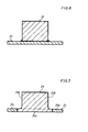
- An internally toothed race 2 is arranged on the drum jacket 1, which is only slightly indicated, of a heat exchange rotary drum known per se.
- This race 2 is supported on the drum jacket 1 by a number of base plates 3 which are arranged uniformly and spaced over the circumference.
- the base plates 3 protrude on both faces of the race 2 in the axial direction by a corresponding amount.
- the base plates 3 are integrally molded onto the race 2.
- the design of the race 2 can be such that a partial base plate 3a or 3b is cast on only in the area of the associated raceway end face 2a or 2b.
- a corresponding recess 2c is then provided in the axial direction between each two sub-base plates 3a, 3b belonging to a base plate 3.
- the race On the inner circumferential sections 2d, 2d 'which are not provided with underlay plates 3 or partial underlay plates 3a, 3b, the race has an inner diameter which is so much larger than the outer diameter Knife of the drum shell 1 that there is a sufficiently large radial play S between the inner race circumference and the outside of the drum shell 1, so that there is space for wedges 4.5 and the machining of the inner circumference can be kept as low as possible. If the drum shell is exposed to greater radial thermal expansion, then the radial relative movements of the drum shell with respect to the race ring mentioned above are made possible by the radial play S '.
- the race 2 In the circumferential direction, the race 2 is clamped over its washers 3 with the help of the wedges 4, 5, which are always tightened in the axial direction in such a way that the race 2 or its washers 3 are braced completely free of play relative to the drum casing 1.
- the similarly designed wedges 4, 5 are supported in the circumferential direction on abutments which are fastened to the drum shell 1, preferably welded on, and are formed by similar bearing blocks 6 in the exemplary embodiment shown. These bearing blocks 6 are relatively small elements compared to the base plates 3, which also only require correspondingly small fastening weld seams.
- the surfaces 6a of the bearing blocks 6 which cooperate with the associated wedge 4, 5 are designed or arranged such that they are adapted to the wedge side 4a or 5a with the wedge inclination.
- these bearing blocks 6 only two need be assigned to each wedge 4, 5, namely one bearing block 6 next to its end face 2a or 2b of the raceway 2
- a wedge 4 or 5 is arranged on both longitudinal sides of each base plate 3. So that each wedge 4, 5 can be tightened in the drum axis direction and, if necessary (e.g. in the event of signs of wear) can also be readjusted or retightened later, in order to always maintain the desired play-free connection, a threaded rod 7 pointing in the drum axis direction is attached to each narrow wedge end, while on the Drum shell 1 a web-like bracket 8 attached in the manner of an abutment, for example is welded, through which the associated threaded rod 7 extends and is held in place with an adjusting nut 9. In this way, an adjustable tightening device results for each wedge 4, 5.
- each base plate 3 is assigned an S ich ceremoniessklotz 10 at one axial end face of which is welded in a corresponding position on the drum shell. 1 If the race 2 is viewed in the circumferential direction, then in this exemplary embodiment the securing blocks 10 on the opposite axial end face are each assigned to the adjacent base plates 3.
- the underlay plates 3 ' can be formed in the same way as in the previous example and attached to the race 2', i.e. be cast on.
- the base plates do not necessarily have to be cast on the race. In many cases, fastening the base plates to the bearing ring by screwing has proven to be particularly advantageous.
- axially continuous support plates 14 are arranged between the drum shell 12 and the race 13, by means of which the race is supported on the drum shell.
- Two radially outwardly projecting lugs 15 are welded onto each base plate 14 at an axial distance from one another which corresponds to the axial dimension of the race 13.
- the race 13 has an annular groove 13a on its inner circumference, so that there are ring webs 13b and 13c in the region of each end face of the race 13 and in the region of the inner circumference.
- Each base plate 14 is now firmly connected to the race 13 in such a way that it is guided against the race 13 from the inner circumferential side and the race is received between the two lugs 15. Screws 16 are then passed through the lugs 15 and through the associated ring webs 13b, 13c of the race 13 is inserted and screwed with the help of nuts 17 from the outside.
- the base plates can also be firmly attached to the inside of the race by welding.
- the underlay plates 21 are designed as continuous and axially aligned plates and are welded to the corresponding circumferential spacings on the inner circumferential side of the race 22.
- An outer part 24b or 24c is welded onto the corresponding end of the middle part 24a of each base plate 24, so that each base plate 24 is composed of the middle part 24a and the two outer parts 24b and 24c in the corresponding overall length.
- the so-internally toothed race 23 or its support plates 24 can then be braced in the same manner as has been explained with reference to FIGS. 1 to 3, that is to say either with two wedges 4, 5 or with one wedge 11 per support plate 24 .
Landscapes
- Engineering & Computer Science (AREA)
- Mechanical Engineering (AREA)
- General Engineering & Computer Science (AREA)
- Centrifugal Separators (AREA)
- Rolling Contact Bearings (AREA)
- General Details Of Gearings (AREA)
Applications Claiming Priority (2)
| Application Number | Priority Date | Filing Date | Title |
|---|---|---|---|
| DE3145901 | 1981-11-19 | ||
| DE19813145901 DE3145901A1 (de) | 1981-11-19 | 1981-11-19 | "drehtrommel" |
Publications (2)
| Publication Number | Publication Date |
|---|---|
| EP0080040A2 true EP0080040A2 (fr) | 1983-06-01 |
| EP0080040A3 EP0080040A3 (fr) | 1983-08-03 |
Family
ID=6146737
Family Applications (1)
| Application Number | Title | Priority Date | Filing Date |
|---|---|---|---|
| EP82108734A Withdrawn EP0080040A3 (fr) | 1981-11-19 | 1982-09-21 | Tambour rotatif |
Country Status (4)
| Country | Link |
|---|---|
| EP (1) | EP0080040A3 (fr) |
| BR (1) | BR8206612A (fr) |
| DE (1) | DE3145901A1 (fr) |
| ZA (1) | ZA827246B (fr) |
Families Citing this family (3)
| Publication number | Priority date | Publication date | Assignee | Title |
|---|---|---|---|---|
| DE3801231A1 (de) * | 1988-01-18 | 1989-07-27 | Krupp Polysius Ag | Drehtrommel mit laufring |
| DK171152B1 (da) | 1994-06-16 | 1996-07-01 | Smidth & Co As F L | Rotertromle ophængt i løbering |
| DE10256758A1 (de) * | 2002-12-05 | 2004-06-17 | Khd Humboldt Wedag Ag | Befestigung eines Laufringes auf dem Mantel eines Drehrohres |
Family Cites Families (16)
| Publication number | Priority date | Publication date | Assignee | Title |
|---|---|---|---|---|
| US2198820A (en) * | 1939-03-30 | 1940-04-30 | Struthers Wells Titusville Cor | Tire mounting for rotary driers, kilns, and similar equipment |
| DE939738C (de) * | 1944-02-22 | 1956-03-01 | Polysius Gmbh | Befestigung von Laufringen auf Drehtrommeln, insbesondere Drehrohroefen |
| US2449198A (en) * | 1946-08-28 | 1948-09-14 | Traylor Engineering & Mfg Comp | Riding ring mounting for rotary cylinders |
| DE966138C (de) * | 1950-12-16 | 1957-07-11 | Miag Vertriebs Gmbh | Laufring zur Lagerung einer drehbaren Trommel, insbesondere eines Drehrohrofens |
| US3096127A (en) * | 1960-05-31 | 1963-07-02 | Vickers Armstrongs Ltd | Riding ring for rotary cylinders |
| FR1436028A (fr) * | 1965-03-11 | 1966-04-22 | Fives Lille Cail | Perfectionnement au montage des bandages de four rotatif |
| DE1273268B (de) * | 1966-01-04 | 1968-07-18 | Polysius Gmbh | Drehtrommel-Laufringbefestigung |
| FR1557822A (fr) * | 1967-12-22 | 1969-02-21 | ||
| DE2011244A1 (en) * | 1970-03-10 | 1971-09-23 | Wedag Westfalia Dinnendahl | Rotary tubular kiln support and drive ring fixing method |
| DE2216982C3 (de) * | 1972-04-08 | 1985-08-01 | Klöckner-Humboldt-Deutz AG, 5000 Köln | Anordnung zur Befestigung eines Laufringes auf dem Mantel eines Drehrohres, insbesondere eines Drehrohrofens |
| DE2227412C2 (de) * | 1972-06-06 | 1982-09-23 | Klöckner-Humboldt-Deutz AG, 5000 Köln | Anordnung zur Lagerung eines Laufringes auf dem Mantel eines Drehrohres |
| DE2512051A1 (de) * | 1975-03-19 | 1976-09-30 | Creusot Loire | Anordnung zur befestigung eines ringes auf einem rohrschuss |
| FR2415745A2 (fr) * | 1978-01-30 | 1979-08-24 | Fives Cail Babcock | Dispositif de maintien d'un bandage sur un tambour rotatif |
| DE2806832A1 (de) * | 1978-02-17 | 1979-08-23 | Polysius Ag | Drehbare waermebehandlungstrommel |
| DE2849490C2 (de) * | 1978-11-15 | 1984-04-26 | O & K Orenstein & Koppel Ag, 1000 Berlin | Mittels Laufringen gelagerte Drehtrommel |
| DE2853435A1 (de) * | 1978-12-11 | 1980-06-19 | Krupp Polysius Ag | Drehtrommel |
-
1981
- 1981-11-19 DE DE19813145901 patent/DE3145901A1/de not_active Withdrawn
-
1982
- 1982-09-21 EP EP82108734A patent/EP0080040A3/fr not_active Withdrawn
- 1982-10-04 ZA ZA827246A patent/ZA827246B/xx unknown
- 1982-11-16 BR BR8206612A patent/BR8206612A/pt unknown
Also Published As
| Publication number | Publication date |
|---|---|
| BR8206612A (pt) | 1983-10-04 |
| DE3145901A1 (de) | 1983-06-30 |
| EP0080040A3 (fr) | 1983-08-03 |
| ZA827246B (en) | 1983-08-31 |
Similar Documents
| Publication | Publication Date | Title |
|---|---|---|
| DE10028958B4 (de) | Bremsscheibe für eine Scheibenbremse | |
| DE3333938C2 (de) | Transportkette für Spannmaschinen | |
| DE3304783C2 (fr) | ||
| DE2544498C3 (de) | Gewindering | |
| DE2947537C2 (de) | Reibbelagträger mit auswechselbaren Reibbelägen | |
| DE2836395B1 (de) | Satzfraeser | |
| EP0072415A1 (fr) | Tambour rotatif | |
| DE2754611A1 (de) | Scheibe einer scheibenbremsvorrichtung | |
| EP0012398A1 (fr) | Tambour rotatif | |
| EP0080040A2 (fr) | Tambour rotatif | |
| DE3316759C1 (de) | Geräuschgedämpftes Schienenrad | |
| DE1997948U (de) | Loesbare nutfederverbindung zur halterung streifen- und plattenfoermiger bauteile | |
| DE2552105A1 (de) | Bremsscheibenanordnung, insbesondere fuer schienenfahrzeuge | |
| EP0080039A2 (fr) | Tambour rotatif | |
| EP0773376B1 (fr) | Palier de vilebrequin | |
| DE2361973A1 (de) | Beheizter trockenzylinder fuer papiermaschinen o.dgl. | |
| DE2753284C2 (de) | Schmitzringanordnung zwischen zwei Druckwerkszylindern | |
| DE69900422T2 (de) | Ein Bearbeitungsgerät, insbesondere ein Laserstrahlgerät, mit einem Kragarm | |
| DE69531073T2 (de) | Verriegelungsmutter | |
| DE2701637A1 (de) | Schmitzring fuer rotationsdruckwerke | |
| DE3333218C2 (fr) | ||
| DE3130229C2 (de) | Mehrschneidenwerkzeug | |
| DE2334305A1 (de) | Presswalze fuer eine brikettiermaschine | |
| DE69700808T2 (de) | Arretiervorrichtung zur verwendung auf wellen oder in röhren | |
| DE2836399A1 (de) | Bolzenkaefig fuer selbsteinstellende rollenlager |
Legal Events
| Date | Code | Title | Description |
|---|---|---|---|
| PUAI | Public reference made under article 153(3) epc to a published international application that has entered the european phase |
Free format text: ORIGINAL CODE: 0009012 |
|
| PUAL | Search report despatched |
Free format text: ORIGINAL CODE: 0009013 |
|
| AK | Designated contracting states |
Designated state(s): BE DE FR GB |
|
| AK | Designated contracting states |
Designated state(s): BE DE FR GB |
|
| STAA | Information on the status of an ep patent application or granted ep patent |
Free format text: STATUS: THE APPLICATION IS DEEMED TO BE WITHDRAWN |
|
| 18D | Application deemed to be withdrawn |
Effective date: 19840404 |
|
| RIN1 | Information on inventor provided before grant (corrected) |
Inventor name: KOERTING, REINHARD, ING. GRAD. |