EP0080292B1 - Rotor d'hélicoptère - Google Patents
Rotor d'hélicoptère Download PDFInfo
- Publication number
- EP0080292B1 EP0080292B1 EP82305916A EP82305916A EP0080292B1 EP 0080292 B1 EP0080292 B1 EP 0080292B1 EP 82305916 A EP82305916 A EP 82305916A EP 82305916 A EP82305916 A EP 82305916A EP 0080292 B1 EP0080292 B1 EP 0080292B1
- Authority
- EP
- European Patent Office
- Prior art keywords
- rotor
- rack
- blade
- further characterised
- lock pin
- Prior art date
- Legal status (The legal status is an assumption and is not a legal conclusion. Google has not performed a legal analysis and makes no representation as to the accuracy of the status listed.)
- Expired
Links
- 230000014759 maintenance of location Effects 0.000 claims description 9
- 230000002441 reversible effect Effects 0.000 claims description 7
- 230000013011 mating Effects 0.000 claims description 4
- 230000007246 mechanism Effects 0.000 description 16
- 238000000605 extraction Methods 0.000 description 2
- 238000003780 insertion Methods 0.000 description 2
- 230000007797 corrosion Effects 0.000 description 1
- 238000005260 corrosion Methods 0.000 description 1
- 230000000694 effects Effects 0.000 description 1
- 238000009434 installation Methods 0.000 description 1
- 238000012423 maintenance Methods 0.000 description 1
- 238000012986 modification Methods 0.000 description 1
- 230000004048 modification Effects 0.000 description 1
- 230000002093 peripheral effect Effects 0.000 description 1
Images



Classifications
-
- B—PERFORMING OPERATIONS; TRANSPORTING
- B64—AIRCRAFT; AVIATION; COSMONAUTICS
- B64C—AEROPLANES; HELICOPTERS
- B64C27/00—Rotorcraft; Rotors peculiar thereto
- B64C27/32—Rotors
- B64C27/46—Blades
- B64C27/473—Constructional features
- B64C27/50—Blades foldable to facilitate stowage of aircraft
Definitions
- This invention relates to helicopter rotors and particularly to such rotors incorporating a powered blade folding mechanism adapted to move a rotor blade between a spread position for normal operation and a folded position for storage.
- GB-A-1375658 discloses, in one embodiment, a helicopter rotor having a blade fold mechanism powered by a reversible rotary power source and including a complex system of camming slots, camming surfaces and cam followers adapted to move a single radially extending lock pin and to retain the lock pin in the withdrawn position during folding of the rotor blade.
- GB-A-852841 discloses a helicopter rotor having a blade fold mechanism in which a pair of externally arranged parallel linear actuators drive racks engaged with a pinion to rotate the latter and so cause rotation of a driving member that in turn causes rotation of a locking spindle that through complex linkages and camming arrangements shifts locking bolts and causes folding and unfolding motion of the associated rotor blade.
- An objective of the present invention is, therefore, to provide a helicopter rotor with powered blade folding and locking arrangements that avoid the bulk, complexity and aerodynamic disadvantages of the known powered fold mechanisms.
- this invention provides a helicopter rotor having a rotor hub for rotation about an axis, a plurality of rotor blades each pivotally connected to the hub for movement about a folding axis between an operational spread position and a folded position, lock pins having engaged positions for locking the blades in their spread positions, and a reversible rotary power source for each blade, characterised in that the reversible rotary power source is so arranged that its driving torque reaction is effective between the hub and the associated blade about the folding axis thereof, and is drivingly coupled to a toothed rack carrying a lock pin to move this into and out of its engaged position, and so that driving rotation of the power source in one direction is effective first to move the lock pin out of its engaged position to a released position and thereafter to move the associated blade from its spread position to its folded position, whereas subsequent driving rotation of the power source in the opposite direction is effective first to move the associated blade from its folded position to its spread position and thereafter to move the lock pin to its engaged position.
- the rack and at least one lock pin carried thereby may be slidably mounted in the hub for lateral engagement in an apertured jaw portion in the rotor hub and a mating apertured insert formed on a blade attachment cuff.
- the or each lock pin is located parallel to the rack.
- lock pins fixedly attached to an outer end of the rack.
- a pinion meshed with the rack may be rotationally fixed to a shaft rotatable in the rotor hub, the shaft having a further pinion meshed with a toothed segment gear fixed to a rotatable housing of the rotary power source.
- retention means adapted to retain the or each lock pin in its released position and such means may comprise a spring-loaded latch pivotally attached to the rotor hub and having an outwardly extending arm for engagement by a stop means on the rack when the or each lock pin is in its released position, and an inwardly extending arm for engagement by a surface of the insert entering the jaw portion as the blade moves towards its spread position, thereby pivoting the latch so that the outwardly extending arm disengages from the stop means.
- a spring-loaded latch pivotally attached to the rotor hub and having an outwardly extending arm for engagement by a stop means on the rack when the or each lock pin is in its released position, and an inwardly extending arm for engagement by a surface of the insert entering the jaw portion as the blade moves towards its spread position, thereby pivoting the latch so that the outwardly extending arm disengages from the stop means.
- a single lock pin is formed integrally at one end of the rack and a pinion meshed with the rack is fixed to a rotatable housing generally centrally of the rotary power source.
- Stop means may be provided in this embodiment to prevent rotational movement of the pinion when the lock pin is in its released position and may comprise an abutment surface formed on the periphery of the pinion and adapted to contact an external surface of the rack when the lock pin is in its released position.
- Retention means may also be provided in this embodiment to retain the lock pin in its released position while the blade is in its folded position.
- the retention means may include an elongated ring located around the periphery of the rack-in a cavity in the hub, this elongated ring having an internal diameter greater than the external diameter of the rack to permit reciprocal radial movement of the ring, spring means adapted to bias the ring radially outwardly to a position in which an edge of the ring prevents rotation of the pinion tending to move the rack when the blade is in the folded position, and a protrusion on the blade cuff adapted to move the ring against the spring bias as the blade is moved towards its spread position.
- the reversible rotary power source may comprise an electrically powered actuator and a speed reducing gearbox and may be located concentrically of the folding axis: the folding axis may be offset from a blade centreline extended through the axis of rotation of the rotor hub.
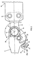
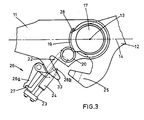
- a helicopter rotor includes a blade fold mechanism generally indicated at 10 and located at the outer end of a forked blade support arm.11 extended radially from a rotor hub (not shown).
- a rotor blade attachment cuff 12 is pivotally connected to arm 11 about a generally vertical axis 13 located on a longitudinal centreline 14.
- the cuff includes two bolted attachments 15 for connection to a rotor blade 16.
- the gearbox 18 includes sun gear 29 and planet carrier 30 which is rotationally fixed to the cuff 12 by a shaft 31 and splines 32.
- the casing of gearbox 18 carries a toothed segment gear 19 meshed with a pinion 20 rotationally fixed at one end of a shaft 21 rotatably supported by the arm 11.
- a further pinion 41 ( Figure 1) is located on the shaft 21 centrally of the forked end of arm 11, and meshes with a toothed rack 22 slidably mounted in the arm 11. Stop means in the form of a raised abutment 28 is located on the surface of the arm 11 for a purpose hereinafter described.
- rack 22 is fixedly attached through a bolted plate 23 to each of two vertically spaced-apart lock pins 24 (one only being shown) which are located parallel to the rack 22 and slidably mounted in the arm 11 for selective engagement through apertured jaw portions 33 on the arm 11 and mating inserts 25 formed on an extension of the cuff 12.
- retention means comprising a latch mechanism generally indicated at 26 is pivotally mounted on the arm 11.
- the mechanism 26 has a first arm 26a extending outwardly generally parallel to the rack 22 and terminating in a shaped outer end adapted for a purpose to be hereinafter described.
- a second arm 26b extends generally inwardly for contact with an outer surface of one of the inserts 25, and spring means (not shown) is adapted to force the arm 26b into contact with the inserts 25.
- a stop surface 27 carried by the rack 22 is adapted for operative engagement with the arm 26a of mechanism 26 during certain phases of operation.
- FIGS. 4 to 9 inclusive illustrate a further embodiment of the invention in which like reference numerals have been used to indicate similar parts.
- the blade support arm 11 is pivotally attached to a forked blade attachment cuff about a generally vertical axis 13 which is offset from the longitudinal axis 14, the blade cuff 12 including two bolted attachments 15 for a rotor blade 16.
- the blade cuff 12 includes a single central apertured locking insert 25 for engagement in an apertured jaw portion 33 on the arm 11, locking being accomplished by a lock pin 24 formed integrally at one end of a rack 22 slidably mounted in an aperture in arm 11 for reciprocal sliding movement in a direction generally perpendicular to axis 14.
- Stop means in the form of an abutment surface 35 is formed on the periphery of the pinion 34.
- An open-ended cavity 36 is formed in the arm 11 and houses retention means in the form of an elongated ring 37. ( Figures 8 and 9) located around the periphery of the rack 22.
- the ring 37 has an internal diameter greater than an external diameter of the rack 22 to permit reciprocal radial movement of the ring 37 and is biassed radially outwardly by two laterally spaced-apart springs 38.
- a protrusion 39 formed integral with the cuff 12 is adapted to contact the external peripheral surface of the ring 37 during certain phases of operation.
- the engaged arm 26a and stop 27 prevents movement of the rack, and therefore of the lock pins 24, until the inserts 25 are moved back into engagement in the jaw portions 33 in arm 11, thereby contacting arm 26b to pivot arm 26a out of engagement with the stop surface 27.
- Further energisation of the actuator 17 causes rotation of the casing that is effective to drive the rack 22 back into the position illustrated in Figure 2, thereby re-inserting the lock pins 24 to secure the blade 16 in the spread position.
- the actuator 17 is energised to rotate in the opposite direction.
- the tendency for the pinion 34 to rotate counterclockwise is prevented by surface 35 coming into contact with the edge of ring 37 thereby resulting in movement of the blade 16 towards the fully spread position of Figure 6.
- the protrusion 39 contacts the external surface of the ring 37 which is thereby moved inwardly to release the pinion 34 so that, when the insert 25 is fully home, the pinion 34 is rotated counterclockwise to drive the rack 22 serving to re-insert the lock pin 24 into engagement in the mated insert 25 and jaw portion 33.
- the various embodiments of the present invention provide a helicopter rotor incorporating a blade fold mechanism 10 which provides for the extraction of one or more lock pins, blade folding and spreading and re-insertion of the lock pin(s) from a single power source.
- the operating mechanism is arranged so that full power is available for operation of the lock pin(s) 24 during that part of the operational cycle when the folding function of the mechanism is operationally dead.
- the powered blade fold mechanisms of the invention are compact and aerodynamically clean thereby reducing weight and drag.
- the embodiment of Figures 4 to 9 inclusive in which the fold hinge and actuator axis is offset from the longitudinal axis 14 and in which the single lock pin 24 is withdrawn inwardly is particularly attractive.
- the fold hinge axis 13 could be spaced-apart from the axis of the actuator 17, which may further reduce the required space envelope by reducing the height of the actuator/gearbox assembly.
- the location of the pivot axis 13 can be varied in the respective embodiments i.e. the embodiment of Figures 1 to 3 can be modified to locate the axis 13 offset from the longitudinal axis 14 and the embodiment of Figures 4 to 9 can be modified to locate the pivot axis 13 coincident with the longitudinal axis 14.
Landscapes
- Engineering & Computer Science (AREA)
- Mechanical Engineering (AREA)
- Aviation & Aerospace Engineering (AREA)
- Retarders (AREA)
- Transmission Devices (AREA)
Claims (18)
Applications Claiming Priority (2)
| Application Number | Priority Date | Filing Date | Title |
|---|---|---|---|
| GB8134956 | 1981-11-19 | ||
| GB8134956 | 1981-11-19 |
Publications (2)
| Publication Number | Publication Date |
|---|---|
| EP0080292A1 EP0080292A1 (fr) | 1983-06-01 |
| EP0080292B1 true EP0080292B1 (fr) | 1986-07-23 |
Family
ID=10526013
Family Applications (1)
| Application Number | Title | Priority Date | Filing Date |
|---|---|---|---|
| EP82305916A Expired EP0080292B1 (fr) | 1981-11-19 | 1982-11-05 | Rotor d'hélicoptère |
Country Status (3)
| Country | Link |
|---|---|
| US (1) | US4466775A (fr) |
| EP (1) | EP0080292B1 (fr) |
| DE (1) | DE3272187D1 (fr) |
Families Citing this family (17)
| Publication number | Priority date | Publication date | Assignee | Title |
|---|---|---|---|---|
| DE3801010A1 (de) * | 1988-01-15 | 1989-08-03 | Messerschmitt Boelkow Blohm | Rotor, insbesondere fuer ein drehfluegelflugzeug |
| US5628620A (en) * | 1991-09-30 | 1997-05-13 | Arlton; Paul E. | Main rotor system for helicopters |
| GB9204305D0 (en) * | 1992-02-28 | 1992-04-08 | Hamble Aerostructures | Locking device |
| US5322415A (en) * | 1992-11-18 | 1994-06-21 | United Technologies Corporation | Pitch actuation system restraint device for a helicopter blade folding system |
| AUPN617295A0 (en) * | 1995-10-25 | 1995-11-16 | Tristream Propeller Company Pty Limited | An improved propeller |
| FR2765188B1 (fr) * | 1997-06-30 | 1999-09-17 | Eurocopter France | Dispositif pour le repliage d'une pale de rotor de giravion |
| US7857590B1 (en) | 2006-08-11 | 2010-12-28 | Neal Larry R | Folding rotor for a rotorcraft |
| WO2010141132A2 (fr) | 2009-04-28 | 2010-12-09 | Sikorsky Aircraft Corporation | Valve de détecteur de proximité et système de verrouillage utilisant celle-ci |
| US11958588B2 (en) | 2015-11-11 | 2024-04-16 | Anduril Industries, Inc. | Foldable propeller blade with locking mechanism |
| US12491983B2 (en) | 2015-11-11 | 2025-12-09 | Anduril Industries, Inc. | Aerial vehicle with deployable components and configurable gearbox |
| US11117649B2 (en) * | 2015-11-11 | 2021-09-14 | Area-I Inc. | Foldable propeller blade with locking mechanism |
| GB2550410A (en) * | 2016-05-20 | 2017-11-22 | Airbus Operations Ltd | Folding wing tip and rotating locking member |
| IL300908B2 (en) | 2017-03-28 | 2025-09-01 | Anduril Industries Inc | Folding propeller blade with locking mechanism |
| CN108583864A (zh) * | 2018-06-06 | 2018-09-28 | 中国船舶重工集团公司第七〇九研究所 | 一种带自锁功能的多旋翼飞行器折叠桨展开机构 |
| FR3111325B1 (fr) * | 2020-06-16 | 2022-12-09 | Safran Helicopter Engines | Ensemble propulsif a helice a pales repliables et procede de repliement des pales |
| US12162594B2 (en) * | 2021-08-24 | 2024-12-10 | Textron Innovations Inc. | Chord lock assembly for a tiltrotor aircraft |
| CN114313250A (zh) * | 2022-01-04 | 2022-04-12 | 广东汇天航空航天科技有限公司 | 折叠装置、螺旋桨、旋翼模组及飞行设备 |
Family Cites Families (9)
| Publication number | Priority date | Publication date | Assignee | Title |
|---|---|---|---|---|
| GB852841A (en) * | 1957-12-10 | 1960-11-02 | Westland Aircraft Ltd | Improvements in or relating to rotary wing aircraft |
| US3097701A (en) * | 1960-10-27 | 1963-07-16 | United Aircraft Corp | Blade folding mechanism |
| US3247907A (en) * | 1963-09-18 | 1966-04-26 | Boeing Co | Blade folding mechanism for rotary wing aircraft |
| US3343610A (en) * | 1965-06-29 | 1967-09-26 | Vacca Luigi | Mechanical blade locks |
| US3369610A (en) * | 1966-12-07 | 1968-02-20 | Boeing Co | Aircraft blade folding mechanism |
| GB1333852A (en) * | 1971-02-05 | 1973-10-17 | Westland Aircraft Ltd | Helicopters |
| GB1333853A (en) * | 1971-02-26 | 1973-10-17 | Westland Aircraft Ltd | Helicopters |
| US3749515A (en) * | 1971-06-01 | 1973-07-31 | Textron Inc | Powered folding mechanism |
| EP0057053A1 (fr) * | 1981-01-22 | 1982-08-04 | WESTLAND plc | Rotor d'hélicoptère |
-
1982
- 1982-11-05 EP EP82305916A patent/EP0080292B1/fr not_active Expired
- 1982-11-05 DE DE8282305916T patent/DE3272187D1/de not_active Expired
- 1982-11-09 US US06/440,285 patent/US4466775A/en not_active Expired - Fee Related
Also Published As
| Publication number | Publication date |
|---|---|
| DE3272187D1 (en) | 1986-08-28 |
| EP0080292A1 (fr) | 1983-06-01 |
| US4466775A (en) | 1984-08-21 |
Similar Documents
| Publication | Publication Date | Title |
|---|---|---|
| EP0080292B1 (fr) | Rotor d'hélicoptère | |
| US5868351A (en) | Rotor blade stowing system | |
| US4436483A (en) | Helicopter rotors | |
| US5950963A (en) | Fin lock mechanism | |
| EP0455797B1 (fr) | Procede et appareil pour replier et verrouiller des pales d'un rotor | |
| US6260799B1 (en) | Aircraft wing fold actuation system | |
| US5288037A (en) | Catch device for locking aircraft landing gear in the raised position | |
| JP2590318B2 (ja) | ラム空気タ−ビンおよび展開機構 | |
| US6889578B2 (en) | Electro-mechanical actuator | |
| US6030177A (en) | Drive system for a variable diameter tilt rotor | |
| US4738592A (en) | Cam assisted blade folding system | |
| EP2597304B1 (fr) | Eolienne avec dispositif de changement de pas synchrone à un seul entraînement pour plusieurs aubes | |
| US4284387A (en) | Blade fold restraint system | |
| JP2005537434A (ja) | 自動再ロックを有する逆推力装置アクチュエータおよびロックドロップ防止機構 | |
| CN114313250A (zh) | 折叠装置、螺旋桨、旋翼模组及飞行设备 | |
| JPS60280B2 (ja) | 回転翼航空機における羽根折りたたみ機構 | |
| US8979496B2 (en) | System for varying the angle of attack of the blades of an aircraft turbine engine propeller, using a brushless electric motor | |
| WO2000037311A1 (fr) | Systeme d'actionnement de pale de rotor a diametre variable | |
| EP3756981B1 (fr) | Structure déflecteur actif pouvant s'ouvrir par rotation | |
| US4373690A (en) | Deployable support structure for spacecrafts | |
| US5782606A (en) | Device for folding a rotorcraft rotor blade | |
| CN109070992A (zh) | 无人机的机架组件及无人机 | |
| CN116374252A (zh) | 一种无人机用收桨装置及其收桨方法 | |
| CN219029589U (zh) | 一种电动尾翼动力装置及电动尾翼 | |
| CN117585148A (zh) | 一种用于飞行器桨叶折叠的折叠装置 |
Legal Events
| Date | Code | Title | Description |
|---|---|---|---|
| PUAI | Public reference made under article 153(3) epc to a published international application that has entered the european phase |
Free format text: ORIGINAL CODE: 0009012 |
|
| AK | Designated contracting states |
Designated state(s): DE FR GB IT |
|
| 17P | Request for examination filed |
Effective date: 19831007 |
|
| ITF | It: translation for a ep patent filed | ||
| GRAA | (expected) grant |
Free format text: ORIGINAL CODE: 0009210 |
|
| AK | Designated contracting states |
Kind code of ref document: B1 Designated state(s): DE FR GB IT |
|
| REF | Corresponds to: |
Ref document number: 3272187 Country of ref document: DE Date of ref document: 19860828 |
|
| ET | Fr: translation filed | ||
| PLBE | No opposition filed within time limit |
Free format text: ORIGINAL CODE: 0009261 |
|
| STAA | Information on the status of an ep patent application or granted ep patent |
Free format text: STATUS: NO OPPOSITION FILED WITHIN TIME LIMIT |
|
| 26N | No opposition filed | ||
| PGFP | Annual fee paid to national office [announced via postgrant information from national office to epo] |
Ref country code: GB Payment date: 19901026 Year of fee payment: 9 |
|
| PG25 | Lapsed in a contracting state [announced via postgrant information from national office to epo] |
Ref country code: GB Effective date: 19911105 |
|
| ITTA | It: last paid annual fee | ||
| GBPC | Gb: european patent ceased through non-payment of renewal fee | ||
| PGFP | Annual fee paid to national office [announced via postgrant information from national office to epo] |
Ref country code: FR Payment date: 19921109 Year of fee payment: 11 |
|
| PGFP | Annual fee paid to national office [announced via postgrant information from national office to epo] |
Ref country code: DE Payment date: 19921123 Year of fee payment: 11 |
|
| PG25 | Lapsed in a contracting state [announced via postgrant information from national office to epo] |
Ref country code: FR Effective date: 19940729 |
|
| PG25 | Lapsed in a contracting state [announced via postgrant information from national office to epo] |
Ref country code: DE Effective date: 19940802 |
|
| REG | Reference to a national code |
Ref country code: FR Ref legal event code: ST |