EP0080545A1 - Outil de rasage composé - Google Patents
Outil de rasage composé Download PDFInfo
- Publication number
- EP0080545A1 EP0080545A1 EP81730119A EP81730119A EP0080545A1 EP 0080545 A1 EP0080545 A1 EP 0080545A1 EP 81730119 A EP81730119 A EP 81730119A EP 81730119 A EP81730119 A EP 81730119A EP 0080545 A1 EP0080545 A1 EP 0080545A1
- Authority
- EP
- European Patent Office
- Prior art keywords
- shaving cutter
- serration
- gear
- thin
- cutter
- Prior art date
- Legal status (The legal status is an assumption and is not a legal conclusion. Google has not performed a legal analysis and makes no representation as to the accuracy of the status listed.)
- Granted
Links
- 239000002131 composite material Substances 0.000 title claims abstract description 14
- 125000006850 spacer group Chemical group 0.000 claims description 21
- 239000000945 filler Substances 0.000 claims description 4
- 238000004519 manufacturing process Methods 0.000 description 3
- 238000010438 heat treatment Methods 0.000 description 2
- 238000010276 construction Methods 0.000 description 1
- 230000000694 effects Effects 0.000 description 1
- 239000007788 liquid Substances 0.000 description 1
- 239000000463 material Substances 0.000 description 1
- 239000002184 metal Substances 0.000 description 1
- 239000011347 resin Substances 0.000 description 1
- 229920005989 resin Polymers 0.000 description 1
- 230000001629 suppression Effects 0.000 description 1
Images
Classifications
-
- B—PERFORMING OPERATIONS; TRANSPORTING
- B23—MACHINE TOOLS; METAL-WORKING NOT OTHERWISE PROVIDED FOR
- B23F—MAKING GEARS OR TOOTHED RACKS
- B23F21/00—Tools specially adapted for use in machines for manufacturing gear teeth
- B23F21/28—Shaving cutters
- B23F21/282—Shaving cutters with inserted cutting elements
- B23F21/284—Shaving cutters with inserted cutting elements in exchangeable arrangement
Definitions
- the present invention relates to a shaving cutter for use in the finish processing of gears. It is well known to effect a shaving on a gear cut and processed from a gear blank by a hobbing machine, in order to further enhance the final precision of the gear surface. This shaving is achieved generally by means of a gear type shaving cutter.
- the teeth face of the shaving cutter has a serration consisting of a multiplicity of grooves of an extremely small width extending over the root and the top of the tooth, and the finish cutting of the processed gear is made by the serration edge which functions as a cutting edge.
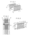
- FIG. 1 shows in a larger scale the serrations formed on both tooth faces of a tooth of a conventional gear type shaving cutter.
- the side surface 1 constituting the serration corresponds to a top rake surface of the serration during the cutting.
- the discontinuous tooth face 2 is referred to as "serration land” and corresponds to a relieving surface during the cutting.
- a reference numeral 3 designates a serration edge.
- the serration pitch P is as small as 2 mm, so that it is extremely difficult to finish the serration face (top rake surface) 1 by grinding.
- the precision of the top rake surface cannot be improved to a level below 6 ⁇ m, because the finish grinding cannot be adopted although the top rake surface is finally processed before a heat treatment.
- an object of the invention is to make it possible to easily grind the serration surface of the shaving cutter thereby to improve the cutting quality or performance of the shaving cutter and to improve the precision of tooth face of the gear to be processed.
- a composite shaving cutter constituted by a plurality of gear thin plates superposed in layers to form a serration in the tooth face of the cutter.
- a reference numeral 4 denotes a blade having a portion corresponding to the serration land of the conventional shaving cutter, while a numeral 5 designates a spacer having a portion corresponding to the serration gap.
- the blade 4 and the spacer 5 are made of a thin plate having a gear-like form.
- the serration is constituted by the combination of the blade 4 and the spacer 5.
- the thickness of the spacer 5 is smaller than the thickness of the blade 4 by an amount corresponding to the serration depth. Both side faces of the blade 4 and the spacer 5 corresponding to the cutter tooth have been beforehand finished by grinding, and the blade 4 and the spacer 5 are assembled together after the finish grinding. As will be seen from FIG. 2 a plurality of blades 4 and a plurality of spacers 5 are superposed in layers alternatingly, and are held together by means of a tie bolt 6.
- the gear-shaped spacers 5' which are disposed at both ends of the cutter teeth have a greater thickness (t) than other spacers, in order to provide a sufficient rigidity of the cutter teeth.
- the blades 4 and the spacers 5 may be united by using, insteadly of the bolt 6, a holder (not shown) in which the blades 4 and the spacers 5 are mounted fixedly.
- the blade 4 projects at its both ends beyond the spacer 5 as will be seen from FIG. 3 to form the serration surface 41 corresponding to the top rake surface of the shaving cutter.
- This surface can easily be finished by grinding in advance to the assembling of the blades 4 and the spacers 5 into one body.
- Both tooth faces of the blade 4 constitute the serration lands 42 corresponding to the relieving surfaces in the cutting of the gear to be processed.
- the corners of the blade 4 constitute the serration edges 43, while the side surfaces of the spacer 5 constitute the bottom 51 of the serration.
- the pitch P of the serration is given as the sum of thicknesses of the pair of blade 4 and spacer 5 constructed in the form of gear-shaped thin plates.
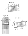
- FIG. 4 shows a second embodiment of the invention in which the gear-shaped plates are arranged at an offset in the circumferential direction and are superposed and united by means of a bolt 6 as in the case of the first embodiment.
- one tooth face of each blade 4 constitutes a serration land 42, while the other constitutes the groove bottom 44 of the serration.
- both side surfaces 41 of the blade 4 have been finished by grinding before the assembling so as to constitute the top rake surfaces.
- the gear-shaped blades 4' disposed at both ends of the cutter teeth have a thickness greater than that of other blades 4.
- the corners of the out- wordly projecting end surface of each blade constitute - the serration edges 43.
- the pitch P of the serration is given as the sum of thicknesses of two blades 4.
- This second embodiment is advantageous in that the shaving cutter can be constructed simply by superposing the blades 4 of the same gear shape at an offset in the circumferential direction, so that the number of kinds of the parts is reduced, although the outermost blades 4' have to have an increased thickness.
- FIGS. 5 and 6 are a sectional view of a half part of the shaving cutter of this embodiment and a perspective view of a part of the cutter teeth.
- teeth of the same shape as the teeth of the shaving cutter are formed on the periphery of a thin disc-shaped plate of a thickness corresponding to the serration pitch P thereby to form a gear-shaped thin plate. Then, the teeth are cut leaving a thickness necessary for constituting the serration land to form a step 81 and the cut surfaces of the teeth are finished by grinding thereby to form a stepped gear-shaped blade 8 which is an element of the shaving cutter of the third embodiment.
- the blades 8 thus formed are superposed and united rigidly by means of the bolt 6, thereby to form a composite shaving cutter in accordance with the invention in which the multiplicity of teeth form the serration.
- a reference numeral 9 designates a serration land, while a reference numeral 10 denotes a serration edge (cutting edge).
- the portion of the teeth from which the material has been removed by the cutting constitute spaces corresponding to the serration gaps as designated at 11.
- the blades 8' disposed at both ends of the cutter teeth are made to have a thickness (t) greater than that of other blades 8 thereby to ensure a sufficient rigidity of the cutter teeth as a whole.
- the cutting performance during the shaving is improved because both surfaces 12 of the teeth 7 of each blade 8, constituting the top rake surfaces during cutting, have been beforehand finished by grinding.
- vacant space 11 is formed between adjacent teeth 7 without using any spacer as shown in FIGS. 2 and 3 the cutting liquid can flow easily during processing, and the removal of metal chips is facilitated.
- the blade thickness i.e. the pitch P of the serration
- the pitch P of the serration is increased as compared with the first and second embodiments shown in FIGS. 2, 3 and FIG. 4, so that the number of the blades can be reduced almost to a half. In consequence, it becomes possible to greatly shorten the production time and to reduce the production cost.
- the increased thickness of the blade permits an easier removal or suppression of the stress in the course of the heat-treatment during manufacturing.
- the teeth size is increased to reduce its mechanical strength, it is advisable to charge a filler such as a hard resin in the space 11 between adjacent teeth 7 and to harden the filler, thereby to reinforce the teeth.
- a filler such as a hard resin
- a composite shaving cutter in which a plurality of gear-shaped thin plates are superposed to form the serration. It is, therefore, possible to beforehand finish by grinding the serration side surfaces corresponding to the top rake surfaces, before assembling the gear thin plates into one body. In consequence, it becomes possible to obtain a shaving cutter having a smoothly finished top rake surfaces and, accordingly, to improve the precision of processing of the gear particularly the precision of the tooth face, when the gear is processed by the shaving cutter of the invention.
Landscapes
- Engineering & Computer Science (AREA)
- Mechanical Engineering (AREA)
- Gear Processing (AREA)
Priority Applications (2)
| Application Number | Priority Date | Filing Date | Title |
|---|---|---|---|
| EP19810730119 EP0080545B1 (fr) | 1981-11-26 | 1981-11-26 | Outil de rasage composé |
| DE8181730119T DE3175966D1 (en) | 1981-11-26 | 1981-11-26 | Composite shaving cutter |
Applications Claiming Priority (1)
| Application Number | Priority Date | Filing Date | Title |
|---|---|---|---|
| EP19810730119 EP0080545B1 (fr) | 1981-11-26 | 1981-11-26 | Outil de rasage composé |
Publications (2)
| Publication Number | Publication Date |
|---|---|
| EP0080545A1 true EP0080545A1 (fr) | 1983-06-08 |
| EP0080545B1 EP0080545B1 (fr) | 1987-03-11 |
Family
ID=8188641
Family Applications (1)
| Application Number | Title | Priority Date | Filing Date |
|---|---|---|---|
| EP19810730119 Expired EP0080545B1 (fr) | 1981-11-26 | 1981-11-26 | Outil de rasage composé |
Country Status (2)
| Country | Link |
|---|---|
| EP (1) | EP0080545B1 (fr) |
| DE (1) | DE3175966D1 (fr) |
Cited By (2)
| Publication number | Priority date | Publication date | Assignee | Title |
|---|---|---|---|---|
| RU2169061C2 (ru) * | 1998-09-08 | 2001-06-20 | Валентин Алексеевич Настасенко | Червячный инструмент, способ его изготовления, оборудование для его изготовления и эксплуатации |
| JP2007185722A (ja) * | 2006-01-11 | 2007-07-26 | Nachi Fujikoshi Corp | 高硬度内歯車仕上げ用シェービングカッタ |
Citations (9)
| Publication number | Priority date | Publication date | Assignee | Title |
|---|---|---|---|---|
| US2119298A (en) * | 1935-11-18 | 1938-05-31 | Michigan Tool Co | Gear finishing tool |
| US2171325A (en) * | 1935-01-30 | 1939-08-29 | Lees Bradner Co | Finishing tool |
| US2228968A (en) * | 1932-02-23 | 1941-01-14 | Fellows Gear Shaper Co | Gear finishing cutter |
| US2667090A (en) * | 1952-12-04 | 1954-01-26 | Eastman Kodak Co | Method of making gear tooth shaving tools |
| FR1104135A (fr) * | 1954-04-30 | 1955-11-16 | Outil de | |
| DE1037812B (de) * | 1957-01-16 | 1958-08-28 | Maschf Augsburg Nuernberg Ag | Werkzeug zum Schaben von Zahnraedern |
| US3505911A (en) * | 1967-11-21 | 1970-04-14 | Lear Siegler Inc | Method of making a gear shaving cutter |
| DE1652797B1 (de) * | 1968-01-08 | 1971-04-01 | Hurth Masch Zahnrad Carl | Zahnrad-Schabwerkzeug mit aus Lamellen bestehendem Radkoerper |
| DE1627347B1 (de) * | 1967-04-22 | 1971-11-25 | Hurth Masch Zahnrad Carl | Schabrad |
-
1981
- 1981-11-26 EP EP19810730119 patent/EP0080545B1/fr not_active Expired
- 1981-11-26 DE DE8181730119T patent/DE3175966D1/de not_active Expired
Patent Citations (9)
| Publication number | Priority date | Publication date | Assignee | Title |
|---|---|---|---|---|
| US2228968A (en) * | 1932-02-23 | 1941-01-14 | Fellows Gear Shaper Co | Gear finishing cutter |
| US2171325A (en) * | 1935-01-30 | 1939-08-29 | Lees Bradner Co | Finishing tool |
| US2119298A (en) * | 1935-11-18 | 1938-05-31 | Michigan Tool Co | Gear finishing tool |
| US2667090A (en) * | 1952-12-04 | 1954-01-26 | Eastman Kodak Co | Method of making gear tooth shaving tools |
| FR1104135A (fr) * | 1954-04-30 | 1955-11-16 | Outil de | |
| DE1037812B (de) * | 1957-01-16 | 1958-08-28 | Maschf Augsburg Nuernberg Ag | Werkzeug zum Schaben von Zahnraedern |
| DE1627347B1 (de) * | 1967-04-22 | 1971-11-25 | Hurth Masch Zahnrad Carl | Schabrad |
| US3505911A (en) * | 1967-11-21 | 1970-04-14 | Lear Siegler Inc | Method of making a gear shaving cutter |
| DE1652797B1 (de) * | 1968-01-08 | 1971-04-01 | Hurth Masch Zahnrad Carl | Zahnrad-Schabwerkzeug mit aus Lamellen bestehendem Radkoerper |
Cited By (2)
| Publication number | Priority date | Publication date | Assignee | Title |
|---|---|---|---|---|
| RU2169061C2 (ru) * | 1998-09-08 | 2001-06-20 | Валентин Алексеевич Настасенко | Червячный инструмент, способ его изготовления, оборудование для его изготовления и эксплуатации |
| JP2007185722A (ja) * | 2006-01-11 | 2007-07-26 | Nachi Fujikoshi Corp | 高硬度内歯車仕上げ用シェービングカッタ |
Also Published As
| Publication number | Publication date |
|---|---|
| EP0080545B1 (fr) | 1987-03-11 |
| DE3175966D1 (en) | 1987-04-16 |
Similar Documents
| Publication | Publication Date | Title |
|---|---|---|
| US2119298A (en) | Gear finishing tool | |
| US5158400A (en) | Rotary disc cutter and method of making same | |
| US2305145A (en) | Cutting tool | |
| EP0080545B1 (fr) | Outil de rasage composé | |
| EP0126096B1 (fr) | Couteau ameliore et procede de fabrication d'engrenage | |
| JPH05504512A (ja) | トウ逃げを設けたフェースホブ切りされたベベルギヤの製造方法 | |
| EP1803974B1 (fr) | Roue dentée chanfreinée | |
| GB2109738A (en) | Dry shaver | |
| US5377457A (en) | Method for generating of gear-shaped precision-working tools, in particular for regrinding shaving gears, and a gear-shaped tool, in particular a shaving gear, to which the method can be applied | |
| US4848976A (en) | Laminated gear shaving tools | |
| JP3283044B2 (ja) | ピンミラーカッタおよびフォームドチップ | |
| JPS5821625Y2 (ja) | セミトッピング付きピニオンカツタ | |
| JPH11114721A (ja) | 組立ホブ | |
| JPS5848025Y2 (ja) | シエ−ビングカツタ | |
| JPH0112904Y2 (fr) | ||
| JPS59102533A (ja) | 切削工具の製造方法 | |
| JPH0327326B2 (fr) | ||
| US3629920A (en) | Gear cutter | |
| JPH0513463Y2 (fr) | ||
| US3091021A (en) | Gear cutter for skew-axis gears | |
| JPH039946Y2 (fr) | ||
| JPS618221A (ja) | 面取刃付シエ−ビングカツタ | |
| US5651644A (en) | Rotary shaving cutter with alternatively arranged plates | |
| EP0665082B1 (fr) | Procédé et outil pour la fabrication des rainures et arêtes de coupes d'une roue de rasage | |
| US3505911A (en) | Method of making a gear shaving cutter |
Legal Events
| Date | Code | Title | Description |
|---|---|---|---|
| PUAI | Public reference made under article 153(3) epc to a published international application that has entered the european phase |
Free format text: ORIGINAL CODE: 0009012 |
|
| 17P | Request for examination filed |
Effective date: 19830117 |
|
| AK | Designated contracting states |
Designated state(s): DE FR GB |
|
| GRAA | (expected) grant |
Free format text: ORIGINAL CODE: 0009210 |
|
| AK | Designated contracting states |
Kind code of ref document: B1 Designated state(s): DE FR GB |
|
| REF | Corresponds to: |
Ref document number: 3175966 Country of ref document: DE Date of ref document: 19870416 |
|
| ET | Fr: translation filed | ||
| PLBI | Opposition filed |
Free format text: ORIGINAL CODE: 0009260 |
|
| 26 | Opposition filed |
Opponent name: CARL HURTH MASCHINEN- UND ZAHNRADFABRIK GMBH & CO. Effective date: 19871006 |
|
| RDAG | Patent revoked |
Free format text: ORIGINAL CODE: 0009271 |
|
| STAA | Information on the status of an ep patent application or granted ep patent |
Free format text: STATUS: PATENT REVOKED |
|
| 27W | Patent revoked |
Effective date: 19881008 |
|
| GBPR | Gb: patent revoked under art. 102 of the ep convention designating the uk as contracting state |