EP0080760B1 - Verfahren und Vorrichtung zum Beheizen eines Zementofens - Google Patents
Verfahren und Vorrichtung zum Beheizen eines Zementofens Download PDFInfo
- Publication number
- EP0080760B1 EP0080760B1 EP82201469A EP82201469A EP0080760B1 EP 0080760 B1 EP0080760 B1 EP 0080760B1 EP 82201469 A EP82201469 A EP 82201469A EP 82201469 A EP82201469 A EP 82201469A EP 0080760 B1 EP0080760 B1 EP 0080760B1
- Authority
- EP
- European Patent Office
- Prior art keywords
- gases
- recycled
- oven
- cement
- raw material
- Prior art date
- Legal status (The legal status is an assumption and is not a legal conclusion. Google has not performed a legal analysis and makes no representation as to the accuracy of the status listed.)
- Expired
Links
- 239000004568 cement Substances 0.000 title claims abstract description 13
- 238000010438 heat treatment Methods 0.000 title claims abstract description 12
- 238000009434 installation Methods 0.000 title claims description 12
- 238000000034 method Methods 0.000 title claims description 7
- 239000007789 gas Substances 0.000 claims abstract description 44
- 239000002994 raw material Substances 0.000 claims abstract description 18
- 238000000354 decomposition reaction Methods 0.000 claims abstract description 8
- 239000000463 material Substances 0.000 claims abstract description 8
- 238000001914 filtration Methods 0.000 claims description 3
- 238000011144 upstream manufacturing Methods 0.000 claims description 3
- 238000001816 cooling Methods 0.000 claims 2
- CURLTUGMZLYLDI-UHFFFAOYSA-N Carbon dioxide Chemical compound O=C=O CURLTUGMZLYLDI-UHFFFAOYSA-N 0.000 description 12
- IJGRMHOSHXDMSA-UHFFFAOYSA-N Atomic nitrogen Chemical compound N#N IJGRMHOSHXDMSA-UHFFFAOYSA-N 0.000 description 10
- XLYOFNOQVPJJNP-UHFFFAOYSA-N water Chemical compound O XLYOFNOQVPJJNP-UHFFFAOYSA-N 0.000 description 9
- 229910002092 carbon dioxide Inorganic materials 0.000 description 6
- 239000001569 carbon dioxide Substances 0.000 description 6
- 230000005855 radiation Effects 0.000 description 6
- 239000000567 combustion gas Substances 0.000 description 5
- 229910052757 nitrogen Inorganic materials 0.000 description 5
- 238000002485 combustion reaction Methods 0.000 description 3
- 238000004064 recycling Methods 0.000 description 3
- VNWKTOKETHGBQD-UHFFFAOYSA-N methane Chemical compound C VNWKTOKETHGBQD-UHFFFAOYSA-N 0.000 description 2
- 238000000926 separation method Methods 0.000 description 2
- 230000005540 biological transmission Effects 0.000 description 1
- 238000006243 chemical reaction Methods 0.000 description 1
- 239000003245 coal Substances 0.000 description 1
- 238000001035 drying Methods 0.000 description 1
- 239000000428 dust Substances 0.000 description 1
- 239000012467 final product Substances 0.000 description 1
- 239000000446 fuel Substances 0.000 description 1
- 239000007788 liquid Substances 0.000 description 1
- 239000000047 product Substances 0.000 description 1
- 239000004449 solid propellant Substances 0.000 description 1
- 238000001228 spectrum Methods 0.000 description 1
Images


Classifications
-
- C—CHEMISTRY; METALLURGY
- C04—CEMENTS; CONCRETE; ARTIFICIAL STONE; CERAMICS; REFRACTORIES
- C04B—LIME, MAGNESIA; SLAG; CEMENTS; COMPOSITIONS THEREOF, e.g. MORTARS, CONCRETE OR LIKE BUILDING MATERIALS; ARTIFICIAL STONE; CERAMICS; REFRACTORIES; TREATMENT OF NATURAL STONE
- C04B7/00—Hydraulic cements
- C04B7/36—Manufacture of hydraulic cements in general
- C04B7/43—Heat treatment, e.g. precalcining, burning, melting; Cooling
- C04B7/44—Burning; Melting
- C04B7/46—Burning; Melting electric
-
- C—CHEMISTRY; METALLURGY
- C04—CEMENTS; CONCRETE; ARTIFICIAL STONE; CERAMICS; REFRACTORIES
- C04B—LIME, MAGNESIA; SLAG; CEMENTS; COMPOSITIONS THEREOF, e.g. MORTARS, CONCRETE OR LIKE BUILDING MATERIALS; ARTIFICIAL STONE; CERAMICS; REFRACTORIES; TREATMENT OF NATURAL STONE
- C04B7/00—Hydraulic cements
- C04B7/36—Manufacture of hydraulic cements in general
- C04B7/43—Heat treatment, e.g. precalcining, burning, melting; Cooling
- C04B7/44—Burning; Melting
- C04B7/4453—Burning; Melting using plasmas or radiations
Definitions
- the heating of a cement kiln is generally carried out by means of a fuel burner in which a pulverized liquid, gaseous or solid fuel is burned in a slight excess of air.
- the hot combustion gases are then sent, generally against the current of the material to be clinkerized, through the rotary kiln.
- the hot gases thus first meet the clinker at around 1400 ° C and finally the dry or wet raw material, as the case may be, at temperatures below 800 ° C either in the oven itself or in a preheating tower upstream thereof relative to the movement of the raw material.
- carbon dioxide and water vapor present both in combustion gases and in gases which result from the decomposition of the raw material, have emission lines in the infrared and therefore contribute effectively when heating the clinker, but these gases constitute only about a quarter of the hot combustion gases.
- the object of the invention is to use for the heating of the cement kiln hot gases with asymmetrical molecules with strong infrared radiation coming from the decomposition of the raw material and this in the absence of appreciable quantities of air or nitrogen. .
- the heating process for a cement kiln is characterized in that the decomposition gases of the raw material are recycled and sent through an electric plasma generator assembly which brings them to temperatures substantially above 1,400 ° C and projects them onto the material subjected to clinkering. It should be noted that in the process according to the invention the cement kiln is not heated with combustion gases, but with gases such as carbon dioxide and water vapor released during the decomposition of the raw material.
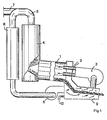
- a rotary oven 1 is powered by a set of electric plasma generators 2 which, thanks to a blower 3, projects hot gas at around 2000 ° C. onto material to be clinkerized which descends into the oven 1.
- L 'set of generators 2 can be constituted at the limit by a single generator as described for example in German patent DE-C3-1 245 509 or by a set of several such generators in parallel.
- the furnace 1 can be supplied with raw, wet or dry material by any suitable supply device, for example a preheating tower 4, in which the gases are collected at least partially by means of a recycling conduit 5.
- the gases collected in line 5 are not only the gases heated in all of the generators 2, but also include the gaseous decomposition products of the raw materials, that is to say mainly carbon dioxide and water vapor, the proportion of water vapor being particularly important in the case where the raw material is introduced in wet form. A significant proportion of water vapor does not disturb the convection heat transfer which takes place in the upstream part of the oven. On the other hand, the almost total absence of nitrogen in the heating gases and its replacement by gases such as carbon dioxide and water vapor appreciably increases the exchange of calories by radiation at the temperatures where takes place clinkering. As a result, the rotary kiln can be shorter and a higher flow rate of raw material can be conveyed there.
- the gases collected by the conduit 5 are partially recycled by means of a blower 6 while the portion of non-recycled gas is sent to the chimney via a conduit 7.
- the blower 6 sends the recycled gases to a clinker cooler. It can be preceded or followed by a filtering or separation device making it possible to remove components harmful to the quality of the final product, that is to say cement, or at least a basic dust removal device 8.
- This cooler can very simply be constituted by an evacuation corridor 9 for the clinker arranged in such a way that the gas supplied by the blower 6 passes through the clinker and thus recovers part of the heat which is stored there.
- the recycled gas is taken up by the blower 3 and conveyed through all of the generators 2 where it is brought again to a temperature of about 2000 ° C.
- This water vapor can be added anywhere in the circuit, for example in the cooler by means of a duct 12.
- the heating gas remains mainly composed of carbon dioxide and water vapor which ensures extremely efficient transmission of heat both when it is by radiation and by convection.
- the preheating in tower 4 further aims to achieve at least partial decarbonation of the raw material.
- This assembly 11 makes it possible to obtain in this tower the temperature necessary for the decarbonation of the raw material.
- the recycling gases consist for the most part of carbon dioxide.
- the processing of wet raw materials generally takes place in installations without a preheating tower, equipped with a very long rotary oven, not shown.
- FIG. 3 Another installation, without a rotary kiln, is shown in FIG. 3.
- the clinkering reaction is carried out in a plasma torch chamber 13, in a duct 14 downstream of this chamber 13 and, mainly in a fluidized or entrained bed 15 maintained at a temperature above 1400 ° C. From the fluidized or entrained bed 15, the clinker is brought by means of a conduit 16 to the inlet of a cooler 17 supplied with cold gases, for example gases at 200 ° C. brought by a conduit 18.
- the cooler 17 ends with a pipe 19 through which the clinker can be extracted at a low temperature, for example at 200 ° C. while the gases which have heated up in contact with the clinker are returned to a temperature of for example 800 ° C. via a conduit 20 in the chamber 13 of the plasma torch.
- the raw material is introduced through a pipe 21 into a first preheater 22 and then passes through a pipe 23 into a second preheater 24 from which it leaves at a temperature of for example 900 ° C. via a pipe 25 which leads it to the chamber 13 of the plasma torch.
- the gas used to heat the material in the second preheater 24 is at a temperature of, for example, 1,200 ° C. and comes from the fluidized or entrained bed 15 from which it leaves via a conduit 26.
- the gas leaving the second preheater 24 via a conduit 27 is brought into the first preheater 22 and then leaves it partly through a chimney 28, partly by a conduit 29 connected to the conduit 14 and partly by the conduit 18 connected to the cooler 17.
- blowers which are not shown can be provided at any convenient place, for example in the conduits 18 and 29. These blowers can also be used for the precise metering of the quantities of gas conveyed by the corresponding conduits.
Landscapes
- Chemical & Material Sciences (AREA)
- Engineering & Computer Science (AREA)
- Ceramic Engineering (AREA)
- Physics & Mathematics (AREA)
- Materials Engineering (AREA)
- Thermal Sciences (AREA)
- Structural Engineering (AREA)
- Organic Chemistry (AREA)
- Plasma & Fusion (AREA)
- Curing Cements, Concrete, And Artificial Stone (AREA)
- Treating Waste Gases (AREA)
- Muffle Furnaces And Rotary Kilns (AREA)
- Processing Of Solid Wastes (AREA)
- Furnace Details (AREA)
- Treatment Of Steel In Its Molten State (AREA)
Claims (8)
Priority Applications (1)
| Application Number | Priority Date | Filing Date | Title |
|---|---|---|---|
| AT82201469T ATE11904T1 (de) | 1981-11-26 | 1982-11-19 | Verfahren und vorrichtung zum beheizen eines zementofens. |
Applications Claiming Priority (2)
| Application Number | Priority Date | Filing Date | Title |
|---|---|---|---|
| EP81201313 | 1981-11-26 | ||
| EP81201313 | 1981-11-26 |
Publications (2)
| Publication Number | Publication Date |
|---|---|
| EP0080760A1 EP0080760A1 (de) | 1983-06-08 |
| EP0080760B1 true EP0080760B1 (de) | 1985-02-20 |
Family
ID=8188167
Family Applications (1)
| Application Number | Title | Priority Date | Filing Date |
|---|---|---|---|
| EP82201469A Expired EP0080760B1 (de) | 1981-11-26 | 1982-11-19 | Verfahren und Vorrichtung zum Beheizen eines Zementofens |
Country Status (6)
| Country | Link |
|---|---|
| EP (1) | EP0080760B1 (de) |
| JP (1) | JPS58120550A (de) |
| AT (1) | ATE11904T1 (de) |
| CA (1) | CA1194301A (de) |
| DE (1) | DE3262452D1 (de) |
| ES (1) | ES8308814A1 (de) |
Families Citing this family (2)
| Publication number | Priority date | Publication date | Assignee | Title |
|---|---|---|---|---|
| JP7077578B2 (ja) * | 2017-11-07 | 2022-05-31 | 三菱マテリアル株式会社 | セメントクリンカー製造方法及び製造装置 |
| KR102040142B1 (ko) * | 2018-02-02 | 2019-11-06 | 성신양회 주식회사 | 시멘트 소성설비용 비이산화탄소 온실가스 처리장치 |
Family Cites Families (2)
| Publication number | Priority date | Publication date | Assignee | Title |
|---|---|---|---|---|
| DE2230590C3 (de) * | 1972-06-22 | 1975-04-10 | Polysius Ag, 4723 Neubeckum | Verwendung der Abgase eines MHD-Generators zur Beheizung eines Drehrohrofens |
| FR2465694A1 (fr) * | 1979-09-24 | 1981-03-27 | Lafarge Sa | Procede de fabrication de produits a base de silicates et/ou aluminates calciques |
-
1982
- 1982-11-19 DE DE8282201469T patent/DE3262452D1/de not_active Expired
- 1982-11-19 EP EP82201469A patent/EP0080760B1/de not_active Expired
- 1982-11-19 AT AT82201469T patent/ATE11904T1/de not_active IP Right Cessation
- 1982-11-24 ES ES517628A patent/ES8308814A1/es not_active Expired
- 1982-11-25 CA CA000416388A patent/CA1194301A/fr not_active Expired
- 1982-11-26 JP JP57207443A patent/JPS58120550A/ja active Pending
Also Published As
| Publication number | Publication date |
|---|---|
| ES517628A0 (es) | 1983-10-01 |
| DE3262452D1 (en) | 1985-03-28 |
| CA1194301A (fr) | 1985-10-01 |
| EP0080760A1 (de) | 1983-06-08 |
| ATE11904T1 (de) | 1985-03-15 |
| JPS58120550A (ja) | 1983-07-18 |
| ES8308814A1 (es) | 1983-10-01 |
Similar Documents
| Publication | Publication Date | Title |
|---|---|---|
| KR100847058B1 (ko) | 오염토양 정화시스템 | |
| EP0108317B1 (de) | Verfahren und Vorrichtung zur Vergasung von holzzellulosehaltigen Produkten | |
| HU216861B (hu) | Eljárás és berendezés laza állagú hulladék termikus ártalmatlanítására | |
| FR2571978A1 (fr) | Procede et installation pour l'epuration des gaz de rebut provenant du traitement des dechets industriels ou menagers. | |
| US4909162A (en) | Installation for low-temperature carbonization of waste and impure materials | |
| FR2484994A1 (fr) | Procede et installation pour la cuisson de matiere a grains fins, plus particulierement pour la fabrication de clinker | |
| CH641749A5 (fr) | Procede et installation pour la fabrication de clinker de cimenterie. | |
| MC1188A1 (fr) | Procede et appareillage pour la pyrolise de residus | |
| FR2656326A1 (fr) | Procedes, dispositifs et fours tournants pour fabriquer en continu du charbon de bois riche en carbone. | |
| FR2573750A1 (fr) | Procede et installation pour produire du clinker de ciment blanc | |
| EP0485255A1 (de) | Verfahren und Vorrichtung zur Herstellung von einem festen Brennstoff ausgehend von brennbaren Abfällen | |
| CA1194301A (fr) | Procede de chauffage pour un four de cimenterie et installation pour le realiser | |
| EP0084279B1 (de) | Verfahren und Einrichtung zur Wärmerückgewinnung, insbesondere bei der Abkühlung von Asche | |
| JP3998127B2 (ja) | 熱分解設備 | |
| CN108679988A (zh) | 一种非直接接触褐煤烘干装置及烘干工艺 | |
| JP4147218B2 (ja) | 炭化処理装置 | |
| FR2482578A1 (fr) | Procede pour refroidir le carbure de calcium fondu et appareillage pour sa mise en oeuvre | |
| EP0011027B1 (de) | Verfahren zur Behandlung eines teilchenförmigen Adsorptionsmaterials, das mit mindestens zwei flüchtigen Verbindungen mit verschiedenen thermischen Stabilitäten beladen ist | |
| JPS5893785A (ja) | 熱分解ガスの製造方法及びこの方法を実施する装置 | |
| JPH1017312A (ja) | 炭化装置 | |
| JP5892832B2 (ja) | 有機性廃棄物の処理装置および有機性廃棄物の処理方法 | |
| KR0165173B1 (ko) | 폐기물의 열처리 장치 | |
| JP2004050074A (ja) | 有機性廃棄物の乾燥と熱分解方法及び装置 | |
| JPH102526A (ja) | 廃棄物処理装置における熱分解反応器 | |
| FR2629179A1 (fr) | Procede de traitement thermique des ordures menageres, qui ne se transforment pas en compost, et installation pour sa mise en oeuvre |
Legal Events
| Date | Code | Title | Description |
|---|---|---|---|
| PUAI | Public reference made under article 153(3) epc to a published international application that has entered the european phase |
Free format text: ORIGINAL CODE: 0009012 |
|
| AK | Designated contracting states |
Designated state(s): AT BE CH DE FR GB IT LI LU NL SE |
|
| 17P | Request for examination filed |
Effective date: 19830623 |
|
| RAP1 | Party data changed (applicant data changed or rights of an application transferred) |
Owner name: ATELIERS DE CONSTRUCTIONS ELECTRIQUES DE CHARLEROI |
|
| ITF | It: translation for a ep patent filed | ||
| GRAA | (expected) grant |
Free format text: ORIGINAL CODE: 0009210 |
|
| AK | Designated contracting states |
Designated state(s): AT BE CH DE FR GB IT LI LU NL SE |
|
| REF | Corresponds to: |
Ref document number: 11904 Country of ref document: AT Date of ref document: 19850315 Kind code of ref document: T |
|
| REF | Corresponds to: |
Ref document number: 3262452 Country of ref document: DE Date of ref document: 19850328 |
|
| PG25 | Lapsed in a contracting state [announced via postgrant information from national office to epo] |
Ref country code: AT Effective date: 19851119 |
|
| PG25 | Lapsed in a contracting state [announced via postgrant information from national office to epo] |
Ref country code: SE Effective date: 19851120 |
|
| PG25 | Lapsed in a contracting state [announced via postgrant information from national office to epo] |
Ref country code: LU Free format text: LAPSE BECAUSE OF NON-PAYMENT OF DUE FEES Effective date: 19851130 Ref country code: LI Effective date: 19851130 Ref country code: CH Effective date: 19851130 |
|
| PLBE | No opposition filed within time limit |
Free format text: ORIGINAL CODE: 0009261 |
|
| STAA | Information on the status of an ep patent application or granted ep patent |
Free format text: STATUS: NO OPPOSITION FILED WITHIN TIME LIMIT |
|
| 26N | No opposition filed | ||
| PG25 | Lapsed in a contracting state [announced via postgrant information from national office to epo] |
Ref country code: NL Effective date: 19860601 |
|
| NLV4 | Nl: lapsed or anulled due to non-payment of the annual fee | ||
| PG25 | Lapsed in a contracting state [announced via postgrant information from national office to epo] |
Ref country code: FR Free format text: LAPSE BECAUSE OF NON-PAYMENT OF DUE FEES Effective date: 19860731 |
|
| REG | Reference to a national code |
Ref country code: CH Ref legal event code: PL |
|
| PG25 | Lapsed in a contracting state [announced via postgrant information from national office to epo] |
Ref country code: DE Effective date: 19860801 |
|
| REG | Reference to a national code |
Ref country code: FR Ref legal event code: ST |
|
| PG25 | Lapsed in a contracting state [announced via postgrant information from national office to epo] |
Ref country code: BE Effective date: 19861130 |
|
| BERE | Be: lapsed |
Owner name: ATELIERS DE CONSTRUCTIONS ELECTRIQUES DE CHARLERO Effective date: 19861130 |
|
| GBPC | Gb: european patent ceased through non-payment of renewal fee | ||
| PG25 | Lapsed in a contracting state [announced via postgrant information from national office to epo] |
Ref country code: GB Effective date: 19881122 |
|
| EUG | Se: european patent has lapsed |
Ref document number: 82201469.2 Effective date: 19860807 |