EP0080895A2 - Méthodes de pesage combinatoire et appareils - Google Patents
Méthodes de pesage combinatoire et appareils Download PDFInfo
- Publication number
- EP0080895A2 EP0080895A2 EP82306365A EP82306365A EP0080895A2 EP 0080895 A2 EP0080895 A2 EP 0080895A2 EP 82306365 A EP82306365 A EP 82306365A EP 82306365 A EP82306365 A EP 82306365A EP 0080895 A2 EP0080895 A2 EP 0080895A2
- Authority
- EP
- European Patent Office
- Prior art keywords
- combinatorial
- weighing
- articles
- batches
- combination
- Prior art date
- Legal status (The legal status is an assumption and is not a legal conclusion. Google has not performed a legal analysis and makes no representation as to the accuracy of the status listed.)
- Granted
Links
Images




Classifications
-
- G—PHYSICS
- G01—MEASURING; TESTING
- G01G—WEIGHING
- G01G13/00—Weighing apparatus with automatic feed or discharge for weighing-out batches of material
- G01G13/24—Weighing mechanism control arrangements for automatic feed or discharge
- G01G13/28—Weighing mechanism control arrangements for automatic feed or discharge involving variation of an electrical variable which is used to control loading or discharge of the receptacle
- G01G13/285—Weighing mechanism control arrangements for automatic feed or discharge involving variation of an electrical variable which is used to control loading or discharge of the receptacle involving comparison with a reference value
-
- G—PHYSICS
- G01—MEASURING; TESTING
- G01G—WEIGHING
- G01G19/00—Weighing apparatus or methods adapted for special purposes not provided for in the preceding groups
- G01G19/387—Weighing apparatus or methods adapted for special purposes not provided for in the preceding groups for combinatorial weighing, i.e. selecting a combination of articles whose total weight or number is closest to a desired value
- G01G19/393—Weighing apparatus or methods adapted for special purposes not provided for in the preceding groups for combinatorial weighing, i.e. selecting a combination of articles whose total weight or number is closest to a desired value using two or more weighing units
Definitions
- the present invention relates to combinatorial weighing methods and apparatus.
- the combinatorial weighing or counting apparatus serves the purpose of delivering a quantity of articles having a set total weight or a set number of articles.
- the apparatus can dispense articles having a total weight precisely or approximately equal to a weight setting, or a desired number of articles having a total weight precisely or approximately equal to a weight setting by means of combinatorial addition of unit weights of articles to be weighed even when the unit weights differ from one another.
- a combinatorial weighing method of measuring out a desired quantity of articles comprising the steps of delivering respective batches of the articles to weighing machines which provide respective measures of the individual weights of those batches; using the said measures to calculate the respective total weights of different combinations of the said batches; identifying that one of the said combinations whose total weight is equal or closest to a preselected value; and bringing together the batches of that one combination, thereby to make up the said desired quantity of articles;
- An embodiment of the present invention can provide a method or an apparatus for effecting combinatorial computation in which the number of items of weighing data utilized for the combinatorial computation is maintained within limits, thereby to reduce the time required for computation.
- a method of or an apparatus for combinatorial computation in which weighing data items produced respectively from a plurality of weighing heads charged with batches of articles randomly are added in combinations to find one out of such combinations which gives a total weight of added data items equal or closest to a set value.
- weighing data items produced by the weighing heads about half of the total number of combinatorial patterns are generated by combinations of weighing data items involving approximately half of the weighing heads. For example, where the number of weighing heads is 10, the number of combinations of weighing data items produced by 5 weighing heads is the greatest reaching substantially half of all the combinations.
- the number of combinations of weighing data items produced by 4 weighing heads is smaller, and the number of combinations of weighing data items produced by 3 weighing heads is much smaller.
- the number of such data item combinations becomes progressively smaller as the number of weighing heads used to produce each combination is reduced. It is highly probable therefore that a combination which gives a weight equal or closest to the set value will be obtained from a selection of combinations of weighing data items generated from substantially half of all of the weighing heads or from any number of weighing heads which is in the vicinity of substantially half of all of the weighing heads. It is likely that it will be of no use if a combination comprising a number of weighing data items which is far from the probable numbers in a "best" combination is computed. In an ernbodiment of the present invention, any combinatorial operations which would probably not give a weight equal or closest to the set value are skipped.
- a method of combinatorial computation embodying the present invention can comprise the steps of: charging batches of articles randomly into a plurality of weighing heads; weighing the batches of articles in the weighing heads to produce weighing data items respectively for the batches; adding in combinations those weighing data items which are smaller in number than the number of all the weighing heads; and comparing added data items in one combination with those added data items'in the previous combination to determine whether the added data items in the one combination are closer than the added data items in the previous combination to a set value, and leaving the combination which gives the added data items closer to the set value, whereby the added data 'items equal or closest to the set value can be determined out of the added data items in all the combinations.
- An apparatus for combinatorial computation embodying the present invention can canprise : a plurality of weighing heads for being charged with batches of articles to be weighed; a combinatorial pattern generating unit for successively generating combinatorial patterns of adding together weighing data items produced respectively by the weighing heads; a combinatorial processing unit for adding the weighing data items according to the combinatorial patterns generated by the combinatorial pattern generating unit; a numerical range setting unit for setting a range for the number of weighing data items to take part in combinatorial adding operation; and a range discriminator for determining whether the number of weighing heads according to a combinatorial pattern produced by the combinatorial pattern generator falls within the range set by the numerical range setting unit, and for skipping combinatorial adding operation and causing the combinatorial pattern generator to produce a next combinatorial pattern when the number of weighing heads falls outside of the range, whereby the weighing data items generated by weighing heads fewer than all of the weighing heads will be added together to find a combination of weighing data items which is equal
- Fig. 1 shows a schematic block diagram of apparatus embodying the present invention, comprising a combinatorial pattern generating unit 1 for sequentially generating patterns of combinatorial adding operation, a combinatorial processing unit 3 for adding in combinations weighing data items D, D, ... produced respectively by a plurality of weighing heads 2, 2, ..., an upper and lower limit setting unit 4 for determining upper and lower limits for the number of'weighing data items which are to be used in the combinatorial addition, and a range discriminator 5 for determining whether the number of combined weighing heads 2 which correspond to a combinatorial pattern given by the combinatorial pattern generating unit 1 falls within the range between the upper and lower limits set by the upper and lower limit setting unit 4.
- the combinatorial pattern is sent to the combinatorial processing unit 3, enabling the latter to perform an ordinary operation for combinatorial addition. Conversely, when the number of combined weighing heads 2 does not fall within the set range, the combinatorial arithmetic operation based on the combinatorial pattern for that number is skipped, and the combinatorial pattern generating unit 1 tnen produces the next combinatorial pattern.
- Fig. 1 It is now assumed in Fig. 1 that there are twelve weighing heads 2, and the number of weighing data items to be used in a combinatorial adding operation ranges from 4 to 9 and is set in the upper'and lower limit setting unit 4.
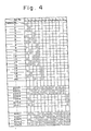
- a start signal S is supplied to the combinatorial pattern generating unit 1, which then successively produces 12-bit combinatorial patterns No. 1 through No. 4095, for instance, as illustrated in Fig. 4.
- the range discriminator 5 compares the number of bits of a logic level "H" (which are indicative of weighing heads that take part in a combinatorial, adding operation) in the combinatorial pattern with the numerical value set in the upper and lower limit setting unit 4.
- the range discriminator 5 immediately delivers a strobe signal ST to the combinatorial pattern generating unit 1 for causing the latter to issue a next combinatorial pattern. If the H-level bit number falls within the set range, that is, the range of from 4 to 9, then the range discriminator 5 enables the combinatorial processing unit 3 to add the weighing data items D, D, ... based on the issued combinatorial pattern.
- the total period of time required for combinatorial operations can be several tens % shorter than that which would otherwise be needed with the conventional process in which combinatorial adding operation should be effected for all of the combinatorial patterns generated.
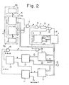
- Fig. 2 shows a combinatorial computation circuit according to a first embodiment of the present invention, the circuit being composed of discrete circuit components.
- the circuit comprises a combinatorial pattern generating unit 1 for successively generating combinatorial patterns of adding operation, a combinatorial processing unit 3 for adding in combinations weighing data items D issued from weighing heads according to the combinatorial patterns, and an upper and lower limit setting unit 4 for establishing upper and lower limits for the number of weighing data items to be employed in combinatorial adding operations, the upper and lower limit setting unit 4 including an upper limit setting device 4a and a lower limit setting device 4b.
- the circuit also has a range discriminator 5 for determining whether the number of combined weighing heads according to a particular combinatorial pattern generated by the combinatorial pattern generating unit 1 falls within the range between the upper and lower limits set by the upper and lower limit setting unit 4.
- the range discriminator 5 is composed of an upper limit discriminating unit 5a and a lower limit discriminating unit 5b.
- a clock pulse generator 6 starts to generate a clock signal (a) in response to a start signal S, and also produces first and second strobes l(b), 2(c) that are short pulses generated at positive-going and negative-going edges, respectively, of the clock signal (a).
- Outputs from the upper and lower limit discriminating units 5a, 5b are supplied to a first OR gate 7, which produces as an output a limit flag (e) of "H" level when the combinatorial pattern falls outside of the set range.
- a first AND gate-8 serves to take the AND of the limit flag (e) and a check signal CH of a short width generated from the combinatorial pattern generating unit 1 right after it has produced a new combinatorial pattern, and generates a limit strobe (f) as an output.
- a delay circuit 9 delays the limit strobe (f) to obtain a strobe 4(g).
- the strobes 4(g), l(b) are ORed by a second OR gate 10, which issues a strobe 3(d) to the combinatorial pattern generating unit 1.
- a first subtracter 11 substracts a set value P from added data A generated by the combinatorial processing unit 3, and produces a signal of "H" level when the difference (A - P) is positive.
- a memory 12 serves to store one of the computed combinatorial patterns which has a number of combined data items that falls within the set range and is closest to the set value P.
- a comparative adder 13 adds weighing data items D according to the combinatorial pattern stored in the memory 12, and produces added data B from which the added data A coming from the combinatorial processing unit 3 is subtracted by a second subtracter 14.
- a second AND gate 15 takes the AND of the output from the first subtracter 11 and the output from the second subtracter 14, and generates a transfer flag (h).
- the strobe 2(c) from the clock pulse generator 6 and the transfer flag (h) are ANDed by a third AND gate 16, which issues a transfer strobe (i) to the memory 12.
- the upper limit U (9, for example) and the lower limit L (4, for exainple) for the number of weighing data items used in combinatorial operation are set respectively in the upper limit setting device 4a and the lower limit setting device 4b.
- the combinatorial operation is started.
- an initializing signal I is supplied to the memory 12 to clear its stored content, and the start signal S is supplied to the clock pulse generator 6, which then starts to generate the clock signal (a) as illustrated in Fig. 3.
- the first strobe l(b) is generated which is delivered through the second OR gate 10 as the strobe 3(d) to the combinatorial pattern generating unit 1.
- the combinatorial pattern generating unit 1 now produce the first combinatorial pattern (the pattern No. 1, for instance, in Fig. 4).
- the range discriminator 5 determines whether the produced combinatorial pattern falls within the set range between the upper and lower limits. When the number of selected weighing heads, that is, the number of "H" level bits, exceeds the upper limit U, the upper limit discriminating unit 5a generates a decision signal of "H" level ( >U). Conversely, when the number is lower than the lower limit L, the lower limit discriminating unit 5b generates a decision signal of "H" level ( ⁇ L).
- the limit flag (e) produced by the first OR gate 7 falls to the "L" level only when the number of selected weighing heads in the combinatorial pattern falls within the set range.
- the combinatorial pattern generating unit 1 supplies the check signal CH to one of the input terminals of the first AND gate 8.
- the output from the first OR gate 7 is then supplied as the limit strobe (f) to the delay circuit 9, which delays the supplied pulse and applies the delayed pulse as the strobe 4(g) to the second OR gate 10.
- the second OR gate 10 supplies the delayed pulse as the strobe 3(d) to the combinatorial pattern generating unit 1.
- the combinatorial pattern generating unit 1 When supplied with the "H" level strobe 3(d), the combinatorial pattern generating unit 1 immediately generates a next combinatorial pattern.
- the range discriminator 5 again determines whether the next combinatorial pattern falls within the set range, and the foregoing cycle of operation is repeated to produce renewed combinatorial patterns until a combinatorial pattern is generated which falls within the set range.
- the pattern renewal cycle of operation is much shorter than the period of the clock pulses (a). Even when the pattern renewal operation is delayed, it will be finished within an interval of time indicated by a hatched area at (h) in Fig. 3; and the apparatus will then enter a combinatorial operation for data comparison.
- cycles 1 and 4 indicate the first and fourth combinatorial patterns which fall within the set range.
- the second combinatorial pattern falls within the set range
- the third combinatorial pattern falls within the set range.
- the combinatorial processing unit 3 adds the weighing data items D supplied from the weighing heads 2, 2, ... according to the combinatorial pattern.
- the added data A which is the result of the adding operation is compared with the set value P in the first subtracter 11.
- a - P > a "H" level signal is issued by the first subtracter 11 to the second AND gate 15.
- the comparative adder 13 adds the weighing data items D according to the combinatorial pattern stored in the memory 12, and produces added data B.
- the second subtracter 14 subtracts the added data A from the added data B.
- the second subtracter 14 When the added data A, which is based on the newly generated combinatorial pattern, is smaller than the data B (B - A > 0), the second subtracter 14 generates a "H" level signal.
- the second AND gate 15 produces the transfer flag (h) of "H" level when both of the outputs from the first and second subtracters 11, 14 are of "H" level, that is, when the added data A according to the newly produced combinatorial pattern is greater than the set value P and smaller than the added data B according to the stored combinatorial pattern.
- the transfer strobe (i) When the strobe 2(c) is generated at a negative-going edge of the clock pulses (a) while the transfer flag (h) is being produced, the transfer strobe (i) is generated in synchronism with the strobe 2(c).
- the transfer strobe (i) enables the memory 12 to store a renewed combinatorial pattern generated by the combinatorial pattern generating unit 1.
- the first combinatorial pattern is generated, there has been no combinatorial pattern stored in the memory 12, and hence the first combinatorial pattern is stored unconditionally in the memory 12.
- Such renewed pattern storage is not effected in each cycle, but carried out only when a transfer flag (h) is set up as a result of a combinatorial operation.
- the stored combinatorial pattern is not renewed as there is no transfer flag produced in that cycle.
- Added data items are successively compared which correspond to combinatorial patterns that are sequentially produced by the clock pulses (a).
- the combinatorial pattern generating unit 1 issues an end signal e to the clock pulse generator 6 only one combinatorial pattern which is equal or closest to the set value P remains stored in the memory 12. Accordingly, the combinatorial operations for all of the combinations are performed while skipping those combinations that are excluded from the set range, resulting in a desired combinatorial pattern left stored in the memory 12.
- the weighing heads 2 that correspond to the bits of "H" level according to the combinatorial pattern stored in the memory 12 are then opened to discharge articles which as a whole have a desired total weight.
- combinatorial data which is closer to the set value P can be obtained by storing successive combinatorial patterns in the memory 12, and computing added data B in the comparative adder 13 based on the previous combinatorial patterns for comparison subsequent to the respective combinatorial operations.
- the present invention is capable of other processes of combinatorial operation.
- the difference between added data and a set value P may be stored in the memory, and added data items may be compared with the stored difference.
- Such an arrangement is shown as a second embodiment in Fig. 5.
- Fig. 5 Identical parts in Fig. 5 are denoted by identical reference characters in Fig. 2.
- the second subtracter 18 produces a signal of " H " level when the difference E' is larger than the absolute difference E (E' - E > 0).
- Operation of the circuit arrangement of Fig. 5 is substantially the same as that of the circuit shown in Fig. 2 except that data available for comparison is composed of the difference stored in the difference memory 17.
- the apparatus shown in F ig. 5 is capable of obtaining a combination of articles having a total weight smaller than the set value P.
- added data according to a previous combinatorial pattern which is closest to a set value P may be stored, and the set value P may be subtracted from the stored data with the difference being supplied to the subtracter for data comparison.
- a combinatorial pattern may be supplied as a parallel input to a shift register in which the data is shifted by the number of all bits contained in the combinatorial pattern, the number of bits of "H" level appearing at a serial output terminal of the shift register may be counted, and the count may be compared with an upper limit setting U and a lower limit setting L.
- Another process may incorporate a digital comparator for direct comparison between the bit number and upper and lower limits.
- Fig. 6 illustrates an analog adder circuit arrangement for effecting analog comparison of such data.
- analog switches AS are supplied respectively with bits of "H" level or “L” level in a combinatorial pattern being supplied through inverters N, and those analog switches AS which are fed with the bits corresponding to the selected weighing heads are energized.
- the energized analog switches AS allow a voltage E 1 to be applied through resistors R to an input of an amplifier Amp.
- n When the number of bits that energize the analog switches AS is n, a current ofnE l/ R flows and is supplied to the amplifier Amp.
- the current of nE 1 /R is compared by the amplifier Amp with a current -E 2/ mR (m is a resistance-divided ratio for determining upper and lower limits U, V) which is set by resistors R', R", ... in a setting unit 4'.
- the result indicative of whether the current is larger or smaller than the set value is supplied as an output signal.of "H” or "L” level from the amplifier Amp.
- the lower limit discriminating unit may be dispensed with, and only the upper limit discriminating unit may be employed.
- Fig. 7 is a flow chart of successive steps of operation under the control of a computer program.
- a memory is initialized by an initializing signal to clear its content.
- the initializing signal is also supplied to a difference memory to clear its content.
- a step 102 determines whether all of combinatorial patterns have been generated. If the answer is "YES”, then the program goes to a step 104 in which the covers of weighing heads corresponding to bits of "H" level in the combinatorial pattern stored in the memory are opened to discharge articles, and all weighing operation is brought to an end.
- step 102 determines whether the answer to the inquiry at the step 102 is "NO”, then the program proceeds to a step 103 in which a next combinatorial pattern is produced.
- a step 105 determines whether the number of selected bits in the combinatorial pattern is smaller than a lower limit L. If the answer is "YES”, then no combinatorial computation is effected, and the program goes back to the step 102. If the answer is "NO”, then the program goes on to a step 106 to see if the number of selected bits is greater than an upper limit U. If the answer is "YES”, then no combinatorial computation is carried out, and the program goes back to the step 102.
- the program proceeds to a step 107 in which data items in the combinatorial pattern added together.
- the weight as thus computed is compared with the set value, and also with a previous optimum weight which is given by combined weighing data items selected in accordance with an optimum combinatorial pattern picked up so far.
- the program goes on to a step 109 in which the combinatorial pattern giving that weight is stored in the memory.
- the program returns to the step 102 to repeat the foregoing cycle of operation. If the answer at the step 108 is "NO”, then the program immediately goes back to the step 102 to perform the repeated cycle of operation.
- a range for the number of preferred weighing data items to be employed for combinatorial operation is defined in advance in a combinatorial weighing or counting machine, and combinatorial operation for combinatorial patterns that do not fall within the defined range is omitted. Therefore, the rate of combinatorial computation can be increased without reducing the precision with which combinatorial counting or weighing operation is performed.
- the present invention is applicable not only to the combinatorial weighing apparatus, but also to the combinatorial counting apparatus, wherein the number of articles stored in each weighing hopper is computed by dividing the weight value by the mean weight value of one article and thereafter obtained is an optimum combination of the weighing hopper whose total number of articles is equal to the target number or closest thereto.
Landscapes
- Physics & Mathematics (AREA)
- General Physics & Mathematics (AREA)
- Weight Measurement For Supplying Or Discharging Of Specified Amounts Of Material (AREA)
- Measurement Of Unknown Time Intervals (AREA)
Applications Claiming Priority (2)
| Application Number | Priority Date | Filing Date | Title |
|---|---|---|---|
| JP193343/81 | 1981-11-30 | ||
| JP56193343A JPS5892914A (ja) | 1981-11-30 | 1981-11-30 | 組合せ演算装置 |
Publications (3)
| Publication Number | Publication Date |
|---|---|
| EP0080895A2 true EP0080895A2 (fr) | 1983-06-08 |
| EP0080895A3 EP0080895A3 (en) | 1984-08-15 |
| EP0080895B1 EP0080895B1 (fr) | 1987-09-09 |
Family
ID=16306312
Family Applications (1)
| Application Number | Title | Priority Date | Filing Date |
|---|---|---|---|
| EP82306365A Expired EP0080895B1 (fr) | 1981-11-30 | 1982-11-30 | Méthodes de pesage combinatoire et appareils |
Country Status (5)
| Country | Link |
|---|---|
| US (1) | US4577707A (fr) |
| EP (1) | EP0080895B1 (fr) |
| JP (1) | JPS5892914A (fr) |
| AU (1) | AU545697B2 (fr) |
| DE (1) | DE3277237D1 (fr) |
Cited By (1)
| Publication number | Priority date | Publication date | Assignee | Title |
|---|---|---|---|---|
| CN112179469A (zh) * | 2020-08-27 | 2021-01-05 | 广东精威智能机器有限公司 | 一种混料称量方法及混料设备 |
Families Citing this family (5)
| Publication number | Priority date | Publication date | Assignee | Title |
|---|---|---|---|---|
| JPS6082929A (ja) * | 1983-10-14 | 1985-05-11 | Ishida Scales Mfg Co Ltd | 組合せ計量装置における組合せ計量方式 |
| JPS63295929A (ja) * | 1987-12-22 | 1988-12-02 | Anritsu Corp | 組合せ計量機の組合せ選定装置 |
| US6899148B1 (en) | 2001-10-11 | 2005-05-31 | Kirby-Lester, Inc. | Method and system for high-speed tablet counting and dispensing |
| US7124791B2 (en) * | 2001-10-11 | 2006-10-24 | Kirby Lester, Llc | Method and system for high-speed tablet counting and dispensing |
| US6684914B2 (en) * | 2001-10-11 | 2004-02-03 | Kirby-Lester, Inc. | Method and system for high-speed discrete object counting and dispensing |
Family Cites Families (12)
| Publication number | Priority date | Publication date | Assignee | Title |
|---|---|---|---|---|
| US3939928A (en) * | 1972-08-12 | 1976-02-24 | Kabushiki Kaisha Ishida Koki Seisakusyo | Weighing method and apparatus |
| DE2730515A1 (de) * | 1977-07-06 | 1979-01-18 | Bayer Ag | Substituierte phenoxybenzyloxycarbonylderivate, verfahren zu ihrer herstellung und ihre verwendung als insektizide und akarizide |
| JPS604106Y2 (ja) * | 1978-12-12 | 1985-02-05 | 大和製衡株式会社 | 組合せ秤 |
| JPS5690219A (en) * | 1979-12-24 | 1981-07-22 | Yamato Scale Co Ltd | Combination scale |
| JPS5690217A (en) * | 1979-12-24 | 1981-07-22 | Yamato Scale Co Ltd | Combination scale |
| JPS5696224A (en) * | 1979-12-28 | 1981-08-04 | Yamato Scale Co Ltd | Combination weighing instrument |
| JPS56100318A (en) * | 1980-01-14 | 1981-08-12 | Yamato Scale Co Ltd | Combined scale |
| US4328874A (en) * | 1980-03-03 | 1982-05-11 | Ohaus Scale Corporation | Digital weighing scale with selectable computational parameters |
| JPS5786014A (en) * | 1980-11-18 | 1982-05-28 | Ishida Scales Mfg Co Ltd | Measuring or counting method by combination |
| US4341274A (en) * | 1981-04-06 | 1982-07-27 | Yamato Scale Company, Ltd. | Combination weighing device |
| GB2100449B (en) * | 1981-06-17 | 1985-05-22 | Yamato Scale Co Ltd | Combination weighing machine |
| JPS5946820A (ja) * | 1982-09-11 | 1984-03-16 | Ishida Scales Mfg Co Ltd | 組合せ計量方法 |
-
1981
- 1981-11-30 JP JP56193343A patent/JPS5892914A/ja active Pending
-
1982
- 1982-11-29 US US06/445,013 patent/US4577707A/en not_active Expired - Fee Related
- 1982-11-29 AU AU90973/82A patent/AU545697B2/en not_active Ceased
- 1982-11-30 DE DE8282306365T patent/DE3277237D1/de not_active Expired
- 1982-11-30 EP EP82306365A patent/EP0080895B1/fr not_active Expired
Cited By (1)
| Publication number | Priority date | Publication date | Assignee | Title |
|---|---|---|---|---|
| CN112179469A (zh) * | 2020-08-27 | 2021-01-05 | 广东精威智能机器有限公司 | 一种混料称量方法及混料设备 |
Also Published As
| Publication number | Publication date |
|---|---|
| DE3277237D1 (en) | 1987-10-15 |
| EP0080895A3 (en) | 1984-08-15 |
| US4577707A (en) | 1986-03-25 |
| AU9097382A (en) | 1983-06-09 |
| EP0080895B1 (fr) | 1987-09-09 |
| AU545697B2 (en) | 1985-07-25 |
| JPS5892914A (ja) | 1983-06-02 |
Similar Documents
| Publication | Publication Date | Title |
|---|---|---|
| US4564918A (en) | Method and apparatus for measuring the time difference between two sampling times | |
| US4549617A (en) | Combinatorial weighing and combinatorial counting method and apparatus | |
| US4396078A (en) | Weighing or counting method with some unfilled hoppers | |
| US4508186A (en) | Weighing method and apparatus therefor | |
| US4442911A (en) | Method and apparatus for controlling zero adjustment of weight sensor | |
| US3623015A (en) | Statistical pattern recognition system with continual update of acceptance zone limits | |
| EP0080895B1 (fr) | Méthodes de pesage combinatoire et appareils | |
| US4465149A (en) | Method of zero adjustment for combinatorial weighing or counting system | |
| US5764045A (en) | Frequency measuring apparatus | |
| US4529049A (en) | Combinatorial weighing or counting method | |
| EP0097977B1 (fr) | Synthétiseur de fréquence | |
| US4491189A (en) | Combinatorial weighing method and apparatus | |
| US4837521A (en) | Delay line control system for automatic test equipment | |
| US4508185A (en) | Combinatorial weighing method | |
| US4610323A (en) | Combination weighing system | |
| JPH0139054B2 (fr) | ||
| JP2645391B2 (ja) | 組合せ計量装置 | |
| US5477174A (en) | Ramp generator | |
| US4625817A (en) | Method of zero adjustment for combinatorial weighing or counting system | |
| US3997769A (en) | Digital decadic indicator device for measured values | |
| JPS6230367B2 (fr) | ||
| JPH0153404B2 (fr) | ||
| US4316177A (en) | Data classifier | |
| JPS6161421B2 (fr) | ||
| JP2645392B2 (ja) | 組合せ計量装置 |
Legal Events
| Date | Code | Title | Description |
|---|---|---|---|
| PUAI | Public reference made under article 153(3) epc to a published international application that has entered the european phase |
Free format text: ORIGINAL CODE: 0009012 |
|
| AK | Designated contracting states |
Designated state(s): DE FR GB IT |
|
| PUAL | Search report despatched |
Free format text: ORIGINAL CODE: 0009013 |
|
| AK | Designated contracting states |
Designated state(s): DE FR GB IT |
|
| 17P | Request for examination filed |
Effective date: 19841220 |
|
| GRAA | (expected) grant |
Free format text: ORIGINAL CODE: 0009210 |
|
| AK | Designated contracting states |
Kind code of ref document: B1 Designated state(s): DE FR GB IT |
|
| REF | Corresponds to: |
Ref document number: 3277237 Country of ref document: DE Date of ref document: 19871015 |
|
| ITF | It: translation for a ep patent filed | ||
| ET | Fr: translation filed | ||
| PLBE | No opposition filed within time limit |
Free format text: ORIGINAL CODE: 0009261 |
|
| STAA | Information on the status of an ep patent application or granted ep patent |
Free format text: STATUS: NO OPPOSITION FILED WITHIN TIME LIMIT |
|
| 26N | No opposition filed | ||
| ITTA | It: last paid annual fee | ||
| PGFP | Annual fee paid to national office [announced via postgrant information from national office to epo] |
Ref country code: FR Payment date: 19951109 Year of fee payment: 14 |
|
| PGFP | Annual fee paid to national office [announced via postgrant information from national office to epo] |
Ref country code: GB Payment date: 19951121 Year of fee payment: 14 |
|
| PGFP | Annual fee paid to national office [announced via postgrant information from national office to epo] |
Ref country code: DE Payment date: 19951128 Year of fee payment: 14 |
|
| PG25 | Lapsed in a contracting state [announced via postgrant information from national office to epo] |
Ref country code: GB Effective date: 19961130 |
|
| GBPC | Gb: european patent ceased through non-payment of renewal fee |
Effective date: 19961130 |
|
| PG25 | Lapsed in a contracting state [announced via postgrant information from national office to epo] |
Ref country code: FR Effective date: 19970731 |
|
| PG25 | Lapsed in a contracting state [announced via postgrant information from national office to epo] |
Ref country code: DE Effective date: 19970801 |
|
| REG | Reference to a national code |
Ref country code: FR Ref legal event code: ST |